Deif AGC 150 Operator's Manual
Hide thumbs
Also See for AGC 150:
- Manual (28 pages) ,
- Operator's manual (25 pages) ,
- Installation instructions manual (22 pages)
Table of Contents
Advertisement
Advertisement
Table of Contents

Related Manuals for Deif AGC 150


Summary of Contents for Deif AGC 150
- Page 1 OPERATOR's MANUAL AGC 150 4189341186E...
-
Page 2: Table Of Contents
1. Introduction 1.1 About the operator's manual ....................................... 1.2 Warnings and safety ..........................................1.3 Legal information ............................................2. Controller overview 2.1 Overview of buttons and LEDs ......................................2.1.1 Display overview ..........................................2.1.2 Display settings ........................................... 2.2 Controller types ............................................2.2.1 Genset controller layouts ........................................ -
Page 3: Introduction 1.1 About The Operator's Manual
The general purpose of this document is to give the operator important information to be used in the daily operation of the controller. DANGER! Read this document before working with the AGC 150 controller. Failure to do this may result in human injury or damage to the equipment. -
Page 4: Warnings And Safety
Warranty CAUTION The AGC 150 controller is not to be opened by unauthorised personnel. If opened anyway, the warranty will be lost. Disclaimer DEIF A/S reserves the right to change any of the contents of this document without prior notice. -
Page 5: Controller Overview
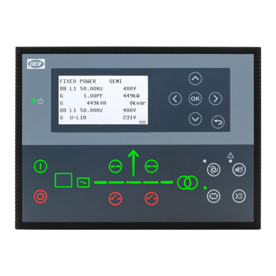
2. Controller overview Overview of buttons and LEDs 2.1.1 Front overview Name Function Green: The controller power is ON. Power ON OFF: The controller power is OFF. Resolution: 240 x 128 px. Display screen Viewing area: 88.50 x 51.40 mm. Six lines, each with 25 characters. -
Page 6: Display Settings
Name Function Green: Breaker is ON. Breaker symbols Green flashing: Synchronising or de-loading. Red: Breaker failure. Green: Generator voltage and frequency are OK. The controller can synchronise and close the breaker. Generator Green flashing: The generator voltage and frequency are OK, but the V&Hz OK timer is still running. The controller cannot close the breaker. -
Page 7: Controller Types
Controller types 2.2.1 Genset controller layouts Single genset controller in Island mode 1. Power ON 2. Display screen (monochrome) 3. Navigation 4. OK 5. Back 6. AUTO mode 7. Silence horn 8. Short cut menu for commands 9. SEMI-AUTO mode 10. - Page 8 Single genset controller in parallel without mains breaker 1. Power ON 2. Display screen (monochrome) 3. Navigation 4. OK 5. Back 6. AUTO mode 7. Silence horn 8. Short cut menu for commands 9. SEMI-AUTO mode 10. Mains symbol 11. Close breaker 12.
-
Page 9: Mains Controller Layouts
2.2.2 Mains controller layouts Mains controller 1. Power ON 2. Display screen (monochrome) 3. Navigation 4. OK 5. Back 6. AUTO mode 7. Silence horn 8. Short cut menu for commands 9. SEMI-AUTO mode 10. Mains symbol 11. Close breaker 12. -
Page 10: Bus Tie Breaker Controller Layouts
2.2.3 Bus tie breaker controller layouts Bus tie braker controller 1. Power ON 2. Display screen (monochrome) 3. Navigation 4. OK 5. Back 6. AUTO mode 7. Silence horn 8. Short cut menu for commands 9. SEMI-AUTO mode 10. - 11. -
Page 11: Hybrid Controller Layouts
2.2.5 Hybrid controller layouts Single genset controller in Island mode 1. Power ON 2. Display screen (monochrome) 3. Navigation 4. OK 5. Back 6. AUTO mode 7. Silence horn 8. Short cut menu for commands 9. SEMI-AUTO mode 10. - 11. -
Page 12: Mimic Function
2.2.6 Mimic function With the Mimic function the operator can choose how the control buttons and LED's are shown on AGC 150, and thereby get a better overview of the controller in different applications. Configure the Mimic function under Settings > Basic settings > Controller settings > Display > LED mimic. - Page 13 Guided Active control buttons and LED's are visible, inactive are not shown. Example: AGC 150 is in SEMI-AUTO mode. The generator is stopped. The only possible action is to start the generator, and so only the Start button is visible.
-
Page 14: Running Modes
3. Running modes Mode overview AGC 150 has four different running modes and one block mode: • AUTO: In AUTO mode, the controller will operate automatically, and the operator cannot initiate any sequences manually. • SEMI-AUTO: In SEMI-AUTO mode, the operator has to initiate all sequences. This can be done via the push-button functions, Modbus commands or digital inputs. -
Page 15: Menu Structure
The View menu When AGC 150 is powered up, the View menu appears. It is the daily use menu for the operator, which shows various measured values. If an alarm is present, the event and alarm list is shown at power-up. -
Page 16: Status Line Texts
Status line texts Status text Condition Comment BLOCK Block mode is activated. SIMPLE TEST LOAD TEST Test mode is activated. FULL TEST SIMPLE TEST ###.#min Test mode is activated and test timer LOAD TEST ###.#min counting down. FULL TEST ###.#min ISLAND MAN Genset stopped or running and no other action taking place. - Page 17 Status text Condition Comment Genset running in mains power export MPE ACTIVE mode. Generator stopped and active alarm(s) on DG BLOCKED FOR START the generator. Generator running, GB open and an GB ON BLOCKED active Trip GB alarm. SHUTDOWN OVERRIDE The configurable input is active.
-
Page 18: Texts Only Related To Power Management
Condition Comment Broadcasts one of the four applications Broadcast of an application through the BROADCASTING APPL. # from one AGC 150 to the other controllers CAN line. in the power management system. RECEIVING APPL. # Receiving an application. BROADCAST COMPLETED Successful broadcast of an application. - Page 19 Comment The new controller is being added to the SETUP IN PROGRESS existing application. Successful update of the application in all SETUP COMPLETED AGC 150 controllers. Remove the power management CAN REMOVE CAN CONNECTOR lines. Table 4.2 DG controller Status text...
-
Page 20: Default Display Views
Default display views Overview of the default display views 1 to 20. The display views are customisable via the Utility Software . Table 4.5 Display view 1 Line Generator Mains Hybrid Engine Drive U-Supply 0.0V U-Supply 0.0V U-Supply 0.0V PV OFF 0kvar 0kW U-Supply 0.0V G 0.00PF 0kW M 0.00PF 0kW... - Page 21 Line Generator Mains Hybrid Engine Drive G U-L3L1 0V M S 0kVA BA S 0kVA G U-L3L1 0V G U-Max 0V M 0 0 0V BA 0 0 0V G U-Max 0V G U-Min 0V M 0 0 0A BA 0 0 0A G U-Min 0V Table 4.10 Display view 6...
- Page 22 Table 4.14 Display view 10 Line Generator Mains Hybrid Engine Drive G U-L1N 0V M U-L1L2 0V Multi input 20 0.0V G U-L1N 0V G U-L2N 0V M U-L2L3 0V Multi input 21 0.0V G U-L2N 0V G U-L3N 0V M U-L3L1 0V Multi input 22 0.0V G U-L3N 0V...
- Page 23 Table 4.18 Display view 14 Line Generator Mains Hybrid Engine Drive Tgt 0kW 0% PV E total 0kWh Tgt 0kvar 0% [yyyy-mm-dd time] PV E year 0kWh Tgt 0.0 Hz 0.0 PV E month 0kWh Tgt 0V L-N 0V MB Operations 0 PV E week 0kWh kW 0% Q 0% TB Operations 0...
-
Page 24: Available Display Texts
Table 4.22 Display view 18 Line Generator Mains Hybrid Engine Drive Multi input 20 0.0V Multi input 20 0.0V Multi input 21 0.0V Multi input 21 0.0V Multi input 22 0.0V Multi input 22 0.0V Multi input 23 0.0V Multi input 23 0.0V MPU 0rpm MPU 0rpm Table 4.23... - Page 25 Table 4.25 Analogue inputs Generator Mains Hybrid Engine Drive Multi input 20 0 Multi input 20 0 Multi input 20 0 Multi input 20 0 Multi input 20 0 Multi input 21 0 Multi input 21 0 Multi input 21 0 Multi input 21 0 Multi input 21 0 Multi input 22 0...
- Page 26 Generator Mains Hybrid Engine Drive Fan B pr. 0 0hrs Fan B pr. 0 0hrs Fan B pr. 0 0hrs Fan C pr. 0 0hrs Fan C pr. 0 0hrs Fan C pr. 0 0hrs Fan D pr. 0 0hrs Fan D pr.
- Page 27 Generator Mains Hybrid Engine Drive BB f-L2 0.00Hz BB f-L2 0.00Hz BB f-L2 0.00Hz BB f-L2 0.00Hz BB f-L3 0.00Hz BB f-L3 0.00Hz BB f-L3 0.00Hz BB f-L3 0.00Hz P BTB Ana21 0kW BB 0 0 0V BB 0 0 0V BB 0 0 0V BB 0 0 0V BB 0 0 0V...
- Page 28 Generator Mains Hybrid Engine Drive Energy Total 0kvarh Energy Total 0kvarh Energy Total 0kvarh Energy Total 0kvarh Energy Total 0kvarh Energy Week 0kWh Energy Week 0kWh Energy Week 0kWh Energy Week 0kWh Energy Week 0kWh Energy Week 0kvarh Energy Week 0kvarh Energy Week 0kvarh Energy Week 0kvarh Energy Week 0kvarh...
- Page 29 Generator Mains Hybrid Engine Drive G U-Max 0V M U-Max 0V BA U-Max 0V G U-Max 0V G U-Max 0V G U-Min 0V M U-Min 0V BA U-Min 0V G U-Min 0V G U-Min 0V Negative volt. 0.0% Negative volt. 0.0% Negative volt.
- Page 30 Generator Mains Hybrid Engine Drive PV curtailed energy, week PV curtailed energy, year PV P energy, day PV P energy, month PV P energy, total PV P energy, week PV P energy, year PV P reference PV Q energy, day PV Q energy, month PV Q energy, total PV Q energy, week...
-
Page 31: The Settings Menu
The Settings menu The Settings menu is used for setting up the controller, and if the operator needs detailed information that is not available in the view menu system. Navigate through the different setup parameters with the Up , Down and OK buttons. -
Page 32: The Service View
DG BLOCKED FOR START Service view Menu numbers In AGC 150 each setting or parameter has a unique menu number. On the display screen, the menu number can be seen in the upper right corner: DG BLOCKED FOR START Generator nom inal U... -
Page 33: The Jump Function
To activate the Jump function in the Utility Software, select the Parameter page and then the Jump menu. 4.11 Engine Drive shortcut menu The AGC 150 has a shortcut menu for configuring the PID set points. To activate the Engine Drive shortcut menu, press the Shortcut button. -
Page 34: Hybrid Shortcut Menu
• Not active during ramp up/down. 4.12 Hybrid shortcut menu The AGC 150 has a shortcut menu for start/stop of the PV inverter in SEMI-AUTO mode. To activate the Hybrid shortcut menu, press the Shortcut button. DG BLOCKED FOR START... -
Page 35: Remote Display Local Menu
Gives you information about the software in the Remote display. 4.14 Exhaust after-treatment (Tier 4 Final/Stage V) AGC 150 supports Tier 4 Final/Stage V requirements, and provides monitoring and control of the exhaust after-treatment system, as requested by the standard. - Page 36 Item Symbol Notes Engine emission system failure Shows an emission failure or malfunction. Diesel Particle Filter (DPF) Shows that a regeneration is needed. Application mode Diesel Particle Filter (DPF) Inhibit Shows that regeneration is inhibited. High temperature - Regeneration Shows a high temperature and regeneration is in process. Engine interface status Shows an engine warning.
-
Page 37: Alarm Handling And Log List
5. Alarm handling and log list Alarm handling If the function Alarm Jump is ON, the controller will automatically show the Alarm list on the display screen, when an alarm occurs. Activate the function under Service View > Display > Alarm Jump. Table 5.1 Parameters for Alarm jump Parameter... -
Page 38: Logs Menu
Access the Alarm list with the Utility Software To open the Alarm list with the Utility Software, press the Alarms button. CAUTION If an alarm is blocking a genset in AUTO mode from starting, the genset will automatically start and close the breaker if the condition that triggered the alarm has disappeared and the alarm has been acknowledged.
Need help?
Do you have a question about the AGC 150 and is the answer not in the manual?
Questions and answers
Hello, I receiving an error of CAN ID 37S on a DEIF AGC 200