
Related Manuals for Deif AGC 200


Summary of Contents for Deif AGC 200
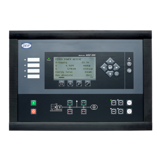
- Page 1 AGC 200 Advanced Gen-set Controller OPERATOR’S MANUAL Display readings Push-button functions Alarm handling Log list Document no.: 4189340607B SW version 3.5X.X or later...
-
Page 2: Table Of Contents
LECTROSTATIC DISCHARGE AWARENESS ..........................4 AFETY ISSUES ..........................4 EFINITIONS ......................... 4 APPLICATIONS AGC 200 VARIANTS ......................5 , AGC 212/222/232/242 ....................5 SLAND , AGC 213/233 ................... 5 UTOMATIC MAINS FAILURE , AGC 245 ......................... 6 AINS , AGC 246 ....................6 AINS AND TIE BREAKER , AGC 244 ...................... -
Page 3: About This Document
1. About this document General purpose This document is the Operator’s Manual for DEIF’s Advanced Gen-set Controllers, the AGC 200 series. The document mainly includes general product information, display readings, push- button and LED functions, alarm handling descriptions and presentation of the log list. -
Page 4: Warnings And Legal Information
2. Warnings and legal information Legal information and responsibility DEIF takes no responsibility for installation or operation of the generator set. If there is any doubt about how to install or operate the generator set controlled by the unit, the company responsible for the installation or the operation of the set must be contacted. -
Page 5: Agc 200 Variants
AGC 200 Operator’s Manual 3. AGC 200 variants Island, AGC 212/222/232/242 Automatic mains failure, AGC 213/233 DEIF A/S Page 5 of 22... -
Page 6: Mains, Agc 245
AGC 200 Operator’s Manual Mains, AGC 245 Mains and tie breaker, AGC 246 DEIF A/S Page 6 of 22... -
Page 7: Bus Tie Breaker, Agc 244
AGC 200 Operator’s Manual Bus tie breaker, AGC 244 DEIF A/S Page 7 of 22... -
Page 8: Display Push-Buttons And Leds
AGC 200 Operator’s Manual 4. Display push-buttons and LEDs Push-button functions The display unit holds a number of push-button functions which are described below. Shifts the display to show the alarm list. Resets horn output. Tools. The tools are a number of windows for commissioning as well as some special settings which are not accessible via the PC utility software. - Page 9 AGC 200 Operator’s Manual Selects MANUAL running mode. Like SEMI, but regulators are OFF. Selects OFF mode. All functions except protections are switched off. TEST Selects TEST RUN of the generator. Lamp test. DEIF A/S Page 9 of 22...
- Page 10 AGC 200 Operator’s Manual The push-buttons are placed as follows: START: Start of the gen-set if ‘SEMI-AUTO’ or ‘MANUAL’ is selected. STOP: Stop of the gen-set if ‘SEMI-AUTO’ or ‘MANUAL’ is selected. View of measured values. Log lists. Parameter settings.
-
Page 11: Led Functions
LED steady light indicates that ALL alarms are acknowledged, but some are still present. Power: LED indicates that the auxiliary supply is switched on. If it is green, the AGC 200 is operational. If it is red, the self-check has failed. Run: LED indicates that the generator is running. - Page 12 AGC 200 Operator’s Manual The display LEDs indicate the following: Mini-annunciator. Engine running. Generator frequency/voltage. Generator breaker ON. Mains breaker ON. Alarm. AUTO mode. Manual mode. SEMI-AUTO. OFF mode. DEIF A/S Page 12 of 22...
-
Page 13: Display And Menu Structure
AGC 200 Operator’s Manual 5. Display and menu structure LCD display The display is a backlit LCD graphical display. The display light intensity, LED indication and contrast can be adjusted from menu 9150. Basically, all measured and calculated values can be read in the display. These may be selected via the PC utility software (USW). - Page 14 AGC 200 Operator’s Manual View menu The view menu is the daily use menu for the operator. First display line MAINS FAILURE Operational status. U- supply 24.1 V 0.00I PF 0 kW Second, third and fourth display lines 0kVA 0 kVAr Measurements.
-
Page 15: Status Line Text
AGC 200 Operator’s Manual Status line text This table explains the different messages. Status text Condition Comment BLOCK Block mode is activated SIMPLE TEST LOAD TEST Test mode is activated FULL TEST SIMPLE TEST ###.#min Test mode is activated and test LOAD TEST ###.#min... - Page 16 AGC 200 Operator’s Manual Status text Condition Comment COMPENSATION FREQ. Compensation is active The frequency is not at the nominal setting Aux. test ##.#V ####s Battery test activated DELOAD Decreasing the load of the gen- set in order to open the breaker...
- Page 17 MOUNT CAN CONNECTOR Connect the power management CAN line ADAPT IN PROGRESS The AGC 200 is receiving the application that it has just been connected to SETUP IN PROGRESS The new AGC is being added to the existing application...
- Page 18 Broadcasts one of the four through the CAN line applications from one unit to the other AGCs in the power management system RECEIVING APPL. # AGC 200 receiving an application BROADCAST COMPLETED Successful broadcast of an application RECEIVE COMPLETED Application received successfully...
- Page 19 AGC 200 Operator’s Manual View menu example View reading (20 views) Log reading Parameter settings Press Press MAINS FAILURE MAINS FAILURE MAINS FAILURE U- supply 24.1 V Event log Setup menu 0.00I PF 0 kW Alarm log 1000 Protection 0kVA...
-
Page 20: Running Modes
The regulators are also active, i.e. the speed control will bring the generator to nominal speed upon start. When pushing a breaker button for closing, the AGC 200 will synchronise (if allowed) the breaker. When the breaker closes, the controls stop. -
Page 21: Alarm Handling And Log List
AGC 200 Operator’s Manual 6. Alarm handling and log list Alarm handling When an alarm occurs, the unit will automatically go to the alarm list, if selected (setting 6900 Alarm jump) for display of the alarm. If setting 6900 is OFF, you have to press to enter the alarm list. -
Page 22: Log List
To enter the log list: 1. Press 2. Select the needed list by using the push-buttons (move the highlight of the list) and press the push-button. DEIF A/S reserves the right to change any of the above DEIF A/S Page 22 of 22...
Need help?
Do you have a question about the AGC 200 and is the answer not in the manual?
Questions and answers