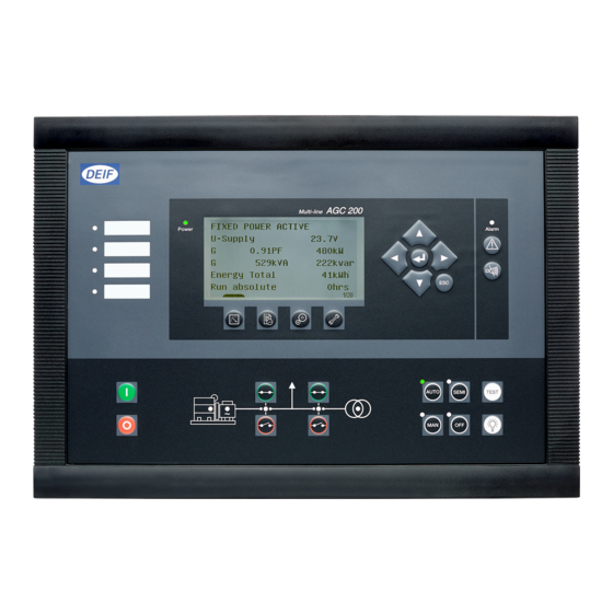
Deif AGC 200 Series General Manuallines For Commissioning
Automatic genset controller
Hide thumbs
Also See for AGC 200 Series:
- Installation instructions manual (67 pages) ,
- Operator's manual (25 pages) ,
- Quick start manual (21 pages)
Table of Contents
Advertisement
GENERAL GUIDELINES FOR COMMISSIONING
DEIF A/S · Frisenborgvej 33 · DK-7800 Skive · Tel.: +45 9614 9614 · Fax: +45 9614 9615 · info@deif.com · www.deif.com
MULTI-LINE 2
● Settings check
● Governor check
● AVR check
● Protections check
● Adjustment
● Troubleshooting
Document no.: 4189340703C
SW version:
Advertisement
Table of Contents


Need help?
Do you have a question about the AGC 200 Series and is the answer not in the manual?
Questions and answers