Deif AGC-4 Operator's Manual
Hide thumbs
Also See for AGC-4:
- Quick start manual (26 pages) ,
- Operator's manual (22 pages) ,
- General manuallines for commissioning (25 pages)

Related Manuals for Deif AGC-4


Summary of Contents for Deif AGC-4
- Page 1 OPERATOR'S MANUAL AGC-4 DEIF A/S · Frisenborgvej 33 · DK-7800 Skive Tel.: +45 9614 9614 · Fax: +45 9614 9615 Document no.: 4189340690E info@deif.com · www.deif.com SW version: 4.79.x or later...
-
Page 2: Table Of Contents
..................................1.2.1 Warnings and notes .......................................... 1.2.2 Factory settings ........................................... 1.2.3 Legal information and disclaimer ....................................2. DU-2 buttons and LEDs 2.1 Display layouts for AGC-4 ........................................2.2 Button functions ............................................2.3 Modes ................................................2.4 LED functions ............................................2.4.1 LED colour schemes ........................................ -
Page 3: General Information
1.2.3 Legal information and disclaimer DEIF takes no responsibility for installation or operation of the generator set or switchgear. If there is any doubt about how to install or operate the engine/generator or switchgear controlled by the Multi-line 2 unit, the company responsible for the installation or the operation of the equipment must be contacted. - Page 4 The English version of this document always contains the most recent and up-to-date information about the product. DEIF does not take responsibility for the accuracy of translations, and translations might not be updated at the same time as the English document.
-
Page 5: Buttons And Leds
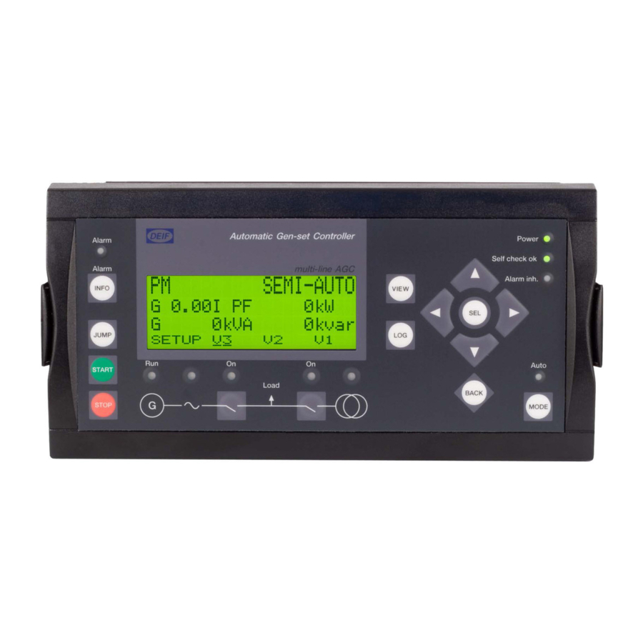
2. DU-2 buttons and LEDs 2.1 Display layouts for AGC-4 INFO The display dimensions are H × W = 115 × 220 mm (4.528” × 8.661”). Engine and generator breaker control (island) (option Y1) Automatic Gen-set Controller Power Alarm Self check ok... - Page 6 Tie breaker and mains breaker control (option Y4) Automatic Gen-set Controller Power Alarm Self check ok multi-line AGC Alarm MAINS Alarm Inh. INFO VIEW JUMP Auto START Load BACK MODE STOP Bus tie breaker control (option Y5) Automatic Gen-set Controller Power Alarm Self check ok...
- Page 7 Group control (option Y8) AGC-4 Power Alarm Self check ok Group Controller Alarm PM CAN INFO VIEW JUMP AUTO BACK SEMI Plant control (option Y9) AGC-4 PF Control Power Alarm Voltage support Self check ok Plant Controller Alarm PM CAN...
-
Page 8: Button Functions
2.2 Button functions Standard AGC-4 folio Automatic Gen-set Controller Power Alarm Self check ok multi-line AGC Alarm Alarm Inh. INFO VIEW JUMP Auto START AUTO Load BACK STOP SEMI MODE AGC - GER (German) folio Automatic Gen-set Controller Power Alarm... - Page 9 • Setup menu: Displays a different value in the second line. • A parameter: Increases the set point. 4. Selects the underscored entry in the fourth line of the display. 5. Moves the cursor right. 6. Down button: Function depends on context. •...
-
Page 10: Modes
2.3 Modes If the MODE button is pushed, a selection of possible running modes appears in the fourth display line. Using the buttons moves the cursor, and the appropriate mode can be selected by pressing the SEL button: Mode Description SEMI •... -
Page 11: Led Functions
2.4 LED functions Standard AGC-4 folio Automatic Gen-set Controller Power Alarm Self check ok Alarm multi-line AGC Alarm Inh. INFO VIEW JUMP Auto START Load BACK MODE STOP AGC - GER (German) folio Automatic Gen-set Controller Power Alarm Selbstest ok... -
Page 12: Led Colour Schemes
6. LED green light indicates that the mains breaker is closed. LED is flashing yellow if the "MB spring loaded" signal from the breaker is missing or the MB load time has not expired. 7. LED green light indicates that the generator breaker is closed. LED yellow light indicates that the generator breaker has received a command to close on a black bus, but the breaker is not yet closed due to interlocking of the GB. -
Page 13: Lcd Display And Menus
3. LCD display and menus 3.1 LCD display The display is a backlit LCD text display. It has four lines with 20 characters in each line. Use parameter 9150 to increase or decrease the brightness. 3.2 Menus The display includes two menu systems. •... -
Page 14: Password Management
For Genset and Group controllers, the priority is shown in the lower right corner of the display. You can use the PC utility software to change the priority. 3.3 Password management The controller includes three password levels. All levels can be adjusted in the PC software. Password level Factory setting Access... -
Page 15: Parameter Access
3.3.1 Parameter access To change parameters, the user must be logged on with the required access level (master, service or customer). If the user is not logged on at the correct access level, it is not possible to change the parameters. INFO The customer password can be changed in jump menu 9116. -
Page 16: Views
Setup example This example shows how a reverse power protection set point is changed. G 400 400 400V G f-L1 50.00HZ PROTECTION SETUP PROT CTRL SYST BACK G 400 400 400V G 400 400 400V 1000 G -P> 1010 G -P> Setpoint -5.0% Setpoint... -
Page 17: Configurable Views V1 And V2
3.5.1 Configurable views V1 and V2 V1 and V2 consist of 20 windows to display the values selected during configuration. V1 and V2 are identical. Select the window to display using the buttons. More information See the Designer’s reference handbook for information about configuration. 3.5.2 Dynamic view V3 The V3 display is dynamic: •... -
Page 18: Status Texts
3.6 Status texts Status text Description ACCESS LOCK The configurable input is activated, and the operator presses one of the blocked keys. ADAPT IN PROGRESS The AGC is receiving the application that it has just connected to. AMF ACTIVE The controller is in auto mode during a mains failure. AMF AUTO The mains controller is in auto mode and ready to respond. - Page 19 Status text Description DERATED TO #####kW Displays the ramp down set point. DG BLOCKED FOR START The generator has stopped and has active alarm(s). DIVIDING SEC IN ###s The BTB will open in ###s. DIVIDING SECTION Power management: A BTB controller is dividing two sections in an island application. DRY ALTERNATOR AUTO The mains controller is in auto mode and ready to respond.
- Page 20 Status text Description The frequency or voltage measurement is outside the limits. The timer shown is the Mains failure MAINS FAILURE IN ###s delay. MAINS f OK DEL ####s Mains frequency is OK after a mains failure. The timer shown is the Mains OK delay. MAINS P EXPORT AUTO The mains controller is in auto mode and ready to respond.
- Page 21 Status text Description SELECT GENSET MODE Power management is deactivated and no other genset mode is selected. SEMI OPERATION Power management, BTB controller: BTB controller in Semi. SENDING DAVR SETUP The AGC is sending settings to the DVC. SETUP COMPLETED Successful update of the application in all AGC controllers.
-
Page 22: Alarm Handling
3.7 Alarm handling When an alarm occurs, the display unit automatically goes to the alarm list to display the alarm. If you do not want to view the alarms, use the BACK button to exit the alarm list. If you decide to enter the alarm list later, use the INFO button to jump directly to the alarm list. The alarm list contains active alarms (that is, the alarm condition is still present), both acknowledged and unacknowledged. -
Page 23: Log List
3.8 Log list The log is divided into three different lists: 1. Events 2. Alarms 3. Battery test The log list contains up to 150 events, the alarm list contains up to 30 historical alarms and the battery test list contains up to 52 historical battery tests. -
Page 24: Maintenance And Disposal
4. Maintenance and disposal 4.1 Maintenance To replace the battery, send your controller(s) to DEIF. As part of this service, DEIF ensures that the controller options are restored. 4.2 Disposal of waste electrical and electronic equipment All products that are marked with the crossed-out wheeled bin (the WEEE symbol) are electrical and WEEE symbol electronic equipment (EEE).
Need help?
Do you have a question about the AGC-4 and is the answer not in the manual?
Questions and answers