Deif AGC 150 Operator's Manual
Generators, mains and btb
Hide thumbs
Also See for AGC 150:
- Operator's manual (38 pages) ,
- Manual (28 pages) ,
- Installation instructions manual (22 pages)
Table of Contents
Advertisement
Advertisement
Table of Contents

Related Manuals for Deif AGC 150


Summary of Contents for Deif AGC 150
- Page 1 OPERATOR'S MANUAL AGC 150 Generators, Mains and BTB 4189341312A...
-
Page 2: Table Of Contents
1.4 Legal information ............................................2. Getting started 2.1 About controller operation ........................................2.1.1 Display settings ........................................... 3. About the AGC 150 Generator 3.1 Display, buttons and LEDs ........................................3.2 Mimic function ............................................. 3.3 Running modes ............................................3.4 Exhaust after-treatment (Tier 4/Stage V) .................................. -
Page 3: Introduction
This document gives the necessary information to operate the controller. CAUTION Installation errors Read this document before working with the AGC 150 controller. Failure to do this may result in human injury or damage to the equipment. Intended users of the operator's manual The operator's manual is for the operator that uses the controller regularly. -
Page 4: Warnings And Safety
Legal information Third party equipment DEIF takes no responsibility for the installation or operation of any third party equipment, including the genset. Contact the genset company if you have any doubt about how to install or operate the genset. Warranty... -
Page 5: Getting Started
About controller operation The AGC 150 Generator controller contains all the functions needed to protect and control a genset, and the genset breaker. If you do not use power management, the controller can also protect and control the mains breaker. -
Page 6: About The Agc 150 Generator
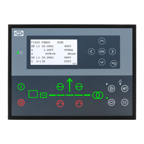
3. About the AGC 150 Generator Display, buttons and LEDs Name Function Green: The controller power is ON. Power OFF: The controller power is OFF. Resolution: 240 x 128 px. Display screen Viewing area: 88.50 x 51.40 mm. Six lines, each with 25 characters. -
Page 7: Mimic Function
Name Function Green flashing: Synchronising or deloading. Red: Breaker failure. Green: Generator voltage and frequency are OK. The controller can synchronise and close the breaker. Generator Green flashing: The generator voltage and frequency are OK, but the V&Hz OK timer is still running. The controller cannot close the breaker. -
Page 8: Running Modes
Running modes The AGC 150 Generator controller has four running modes, and a test mode. To configure the running mode push the Shortcut button and select Running Modes. Configure the test mode in Settings > Power set points > Test. To run the test push the Shortcut button and select Start Test. - Page 9 AGC 150 Tier 4/Stage V screen ISLAND SEMI DEF level: 32.0% 1/20 Referent Symbol Description Engine emission system failure Shows an emission failure or malfunction. Diesel Particle Filter (DPF) Shows that a regeneration is needed. Application mode Diesel Particle Filter (DPF) Inhibit Shows that regeneration is inhibited.
- Page 10 Referent Symbol Description Engine interface status Shows an engine shutdown. LIMIT lamp Only for MTU engines. Diesel Exhaust Fluid (DEF) Shows the fluid tank level is low. Diesel Exhaust Fluid (DEF) % level Shows the level (%) of the Diesel Exhaust Fluid. NOTE Grey symbols show that communication is available for the referent.
-
Page 11: About The Agc 150 Mains
4. About the AGC 150 Mains Display, buttons and LEDs Name Function Green: The controller power is ON. Power OFF: The controller power is OFF. Resolution: 240 x 128 px. Display screen Viewing area: 88.50 x 51.40 mm. Six lines, each with 25 characters. -
Page 12: Mimic Function
The controller is de-loading Running modes The AGC 150 Mains controller has three running modes, and a test mode. Push the Shortcut button and select Running Modes to configure the mode. Configure the test mode in Settings > Power set points > Test. To run the test push the Shortcut button and select Start Test. -
Page 13: About The Agc 150 Btb
5. About the AGC 150 BTB Display, buttons and LEDs Name Function Green: The controller power is ON. Power OFF: The controller power is OFF. Resolution: 240 x 128 px. Display screen Viewing area: 88.50 x 51.40 mm. Six lines, each with 25 characters. -
Page 14: Mimic Function
• The controller is synchronising • The controller is de-loading Running modes The AGC 150 BTB controller has three running modes. To configure the running mode push the Shortcut button and select Running Modes. Mode Description The controller automatically joins and splits the busbar. The operator cannot start a sequence manually. The AUTO controllers use the power management configuration to automatically select the power management action. -
Page 15: Menus
6. Menus Menu structure The AGC 150 has two menu systems, which can be used without password entry: • The View menu system: Shows the operating status and values. The system has 20 configurable windows, that can be entered with the arrow buttons. -
Page 16: Menu Numbers
6.2.1 Menu numbers Each parameter has a menu number. You can find the number in the upper right corner on the display screen. You can also find the menu number with the utility software: 1. Select Parameters from the vertical toolbar on the left. 2. -
Page 17: Display Views
2. Values and information 3. Page number, power management priority, power management ID and engine DEF level. The view menu has 20 different display views. Use the buttons to select a view. AGC 150 Generator example Push AGC 150 Mains example Push... - Page 18 AGC 150 Generator Line View 1 View 2 View 3 View 4 View 5 U-Supply 0.0V BB L1 0.0Hz 0V BB L1 0.0Hz 0V G U-L1L2 0V G 0.00PF 0kW G L1 0.0Hz 0V Synchroniser G 0.00PF 0kW G U-L2L3 0V G 0kVA 0kvar G 0.00PF 0kW...
-
Page 19: Display Text
M 0.00PF 0kW Multi Input 23 0 MB operations BB Angle L1L2 0deg M 0 0 0A Energy Total 0kWh TB Operations BB Angle L2L3 0deg AGC 150 BTB Line View 1 View 2 View 3 View 4 View 5 U-Supply 0.0V BB L1 0.0Hz 0V... -
Page 20: Status Texts
3. Select the display line you want to change. 4. In the pop-up window, select the text you want and click OK. Display text You can select five of the display texts for each display view. Status texts Status text Condition ACCESS LOCK The configurable input is activated, and the operator tries to activate one of the blocked keys. - Page 21 Status text Condition Power management: Broadcast one of the four applications from one controller to the other BROADCASTING APPL. # controllers in the power management system, through the CAN line. BROADCAST COMPLETED Power management: Correct broadcast of an application. BTB power management: External equipment has tripped the breaker, and this is logged in the BTB TRIP EXTERNALLY event log.
- Page 22 Status text Condition The frequency or voltage measurement is outside the limits. The timer shown is the mains failure MAINS FAILURE IN ###s delay. MAINS f OK DEL ####s Mains frequency is OK after a mains failure. The timer shown is the mains OK delay. MAINS P EXPORT AUTO The mains controller is in auto mode and ready to respond.
-
Page 23: Service View
Status text Condition STOP DG(s) IN ###s The stop genset set point has been exceeded. The genset stops when the timer expires. SYNCHRONISING BTB XX Generator power management: BTB XX is synchronising. SYNCHRONISING MB XX Generator power management: MB XX is synchronising. SYNCHRONISING TB XX Generator power management: TB XX is synchronising. -
Page 24: Alarm Handling And Log List
7. Alarm handling and log list Alarm handling If the function Alarm Jump is on, the controller automatically shows the alarm list on the display screen when an alarm occurs. Service View > Display > Alarm Jump Parameter Text Range Default 9157 Alarm Jump... -
Page 25: Logs Menu
CAUTION Caution If an alarm is blocking a genset in AUTO mode from starting, the genset automatically starts if the condition that triggered the alarm has gone and the alarm has been acknowledged. Logs menu These are the log sub-menus: 1.
Need help?
Do you have a question about the AGC 150 and is the answer not in the manual?
Questions and answers
How to power off
To power off the Deif AGC 150, turn off the controller power. The display will show "OFF: The controller power is OFF."
This answer is automatically generated