Table of Contents
Advertisement
Quick Links
INSTALLATION INSTRUCTIONS
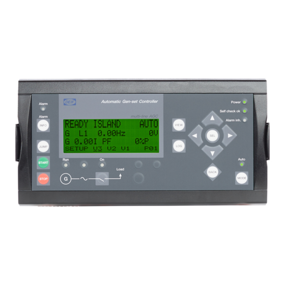
Automatic Genset Controller, AGC-3
● Mounting
● Board slot positions
● Terminal strip overview
● I/O lists
● Wiring
DEIF A/S · Frisenborgvej 33 · DK-7800 Skive · Tel.: +45 9614 9614 · Fax: +45 9614 9615 · info@deif.com · www.deif.com
Document no.: 4189340728E
SW version: 3.4X.X or later
Advertisement
Table of Contents

Related Manuals for Deif AGC-3


Summary of Contents for Deif AGC-3
- Page 1 ● Wiring DEIF A/S · Frisenborgvej 33 · DK-7800 Skive · Tel.: +45 9614 9614 · Fax: +45 9614 9615 · info@deif.com · www.deif.com isenborgvej 33 · DK-7800 Skive · Tel.: +45 9614 9614 · Fax: +45 9614 9615 · info@deif.com · www.deif.com Document no.: 4189340728E...
-
Page 2: Table Of Contents
2.3.6. Mains power export (fixed power to mains)................. 10 2.3.7. Multiple gensets, load sharing..................... 11 2.3.8. Multiple gensets, power management..................11 3. Mounting 3.1. AGC-3 mounting and dimensions......................12 3.1.1. Mounting of the unit........................12 3.1.2. Unit dimensions........................... 12 3.1.3. Panel cutout..........................13 3.1.4. - Page 3 AGC-3 installation instructions 4189340728 4.1.14. Slot #4, PWM output for GOV and combination output for AVR (option EF5)......30 4.1.15. Slot #4, PWM output for GOV and combination output for AVR (option EF6)......30 4.1.16. Slot #4, analogue outputs for GOV/AVR or transducer (option E2)...........31 4.1.17.
-
Page 4: General Information
1.1.2 Legal information and disclaimer DEIF takes no responsibility for installation or operation of the generator set. If there is any doubt about how to install or operate the engine/generator controlled by the Multi-line 2 unit, the company responsible for the installation or the operation of the set must be contacted. -
Page 5: Factory Settings
AGC-3 installation instructions 4189340728 General information 1.1.5 Factory settings The Multi-line 2 unit is delivered from factory with certain factory settings. These are based on average values and are not necessarily the correct settings for matching the engine/generator set in question. Precautions must be taken to check the settings before running the engine/generator set. -
Page 6: General Product Information
2.1 AGC-3 product information 2.1.1 Introduction The AGC is part of the DEIF Multi-line 2 product family. Multi-line 2 is a complete range of multi-function gen- erator protection and control products integrating all the functions you need into one compact and attractive solution. -
Page 7: Busbar Protection (Ansi)
AGC-3 installation instructions 4189340728 General product information ● Current/voltage unbalance (60) ● Loss of excitation/overexcitation (40/32RV) ● Non-essential load/load shedding, 3 levels (I, Hz, P>, P>>) ● Multi-inputs (digital, 4 to 20 mA, 0 to 40 V DC, Pt100, Pt1000 or RMI) ●... -
Page 8: Automatic Mains Failure, Amf
AGC-3 installation instructions 4189340728 General product information 2.3.1 Automatic Mains Failure, AMF Load Controller Setting Setting 6071 Genset mode 2.3.2 Island operation Load Controller Setting Setting 6071 Genset mode Island operation Island operation DEIF A/S Page 8 of 65... -
Page 9: Fixed Power/Base Load
AGC-3 installation instructions 4189340728 General product information 2.3.3 Fixed power/base load Load Controller Setting Setting 6071 Genset mode Fixed power Fixed power 2.3.4 Peak shaving TRANSDUCER 4-20 mA Load Controller Setting Setting 6071 Genset mode Peak shaving Peak shaving DEIF A/S... -
Page 10: Load Takeover
AGC-3 installation instructions 4189340728 General product information 2.3.5 Load takeover TRANSDUCER 4-20 mA Load Controller Setting Setting 6071 Genset mode Load takeover Load takeover 2.3.6 Mains power export (fixed power to mains) TRANSDUCER 4-20 mA Load Controller Setting Setting 6071... -
Page 11: Multiple Gensets, Load Sharing
AGC-3 installation instructions 4189340728 General product information 2.3.7 Multiple gensets, load sharing Load Controller Controller Setting Setting 6071 Genset mode Island operation Island operation 2.3.8 Multiple gensets, power management For information about the power management application, refer to "Description of Option G4, G5 and G8". -
Page 12: Mounting
AGC-3 installation instructions 4189340728 Mounting 3. Mounting 3.1 AGC-3 mounting and dimensions 3.1.1 Mounting of the unit The unit is designed for mounting inside the panel. The display can be installed on the panel door and con- nected to the main unit with a display cable. -
Page 13: Panel Cutout
AGC-3 installation instructions 4189340728 Mounting 3.1.3 Panel cutout In order to ensure optimum mounting, the panel door must be cut out according to the panel cutout illustration in the chapter Technical information. 174.0 26.0 26.0 Required space 222X115mm Gasket outer 186X77mm Screws for fastning: 3.5mm selfcutting threads... -
Page 14: Mounting Instructions
2. Fastened with screws to the rear side of the cabinet. Six screw holes are available for this mounting method. DEIF recommends using the screw hole fastening. Warning in use of chemicals! Do NOT use chemicals or oils (cutting oil, lubricating oil/grease) on or near by the surfaces of the controller housing or display panel. -
Page 15: Hardware
AGC-3 installation instructions 4189340728 Hardware 4. Hardware 4.1 Board slot positions The unit housing is divided into board slot positions. This means that the unit consists of a number of printed circuit boards (PCBs) mounted in numbered slots. The green terminal blocks are then mounted in the PCBs. -
Page 16: Unit Top Side Overview
AGC-3 installation instructions 4189340728 Hardware 4.1.1 Unit top side overview An overview of the terminals is presented below. The slot positions are as follows: 65 66 69 70 53 54 56 57 59 60 61 62 63 CAN A Ethernet... -
Page 17: Terminal Strip Overviews
AGC-3 installation instructions 4189340728 Hardware 4.1.2 Terminal strip overviews Standard unit DEIF A/S Page 17 of 65... - Page 18 AGC-3 installation instructions 4189340728 Hardware The hardware shown in slot #3 is option M12 and G3. For a detailed description of these op- tions, refer to the option manuals. DEIF A/S Page 18 of 65...
- Page 19 AGC-3 installation instructions 4189340728 Hardware Mains unit DEIF A/S Page 19 of 65...
- Page 20 AGC-3 installation instructions 4189340728 Hardware The hardware shown in slot #3 is option M12 and G3. For a detailed description of these op- tions, refer to the option manuals. DEIF A/S Page 20 of 65...
- Page 21 AGC-3 installation instructions 4189340728 Hardware BTB unit DEIF A/S Page 21 of 65...
- Page 22 AGC-3 installation instructions 4189340728 Hardware The hardware shown in slot #3 is option M12 and G3. For a detailed description of these op- tions, refer to the option manuals. DEIF A/S Page 22 of 65...
-
Page 23: Input/Output Lists
AGC-3 installation instructions 4189340728 Hardware 4.1.3 Input/output lists In the I/O lists, the following terms will be used in connection with the relay outputs: NO means Normally Open NC means Normally Closed NE means Normally Energised ND means Normally Deenergised Com. -
Page 24: Slot #1, Power Supply Pcb - Agc Mains Unit
AGC-3 installation instructions 4189340728 Hardware 4.1.5 Slot #1, power supply PCB - AGC mains unit The I/O list below is for the AGC mains unit. Term. Function Technical data Description +12/24 V DC 12/24 V DC Power supply +/-30 %... -
Page 25: Slot #2, Serial Communication (Option H)
AGC-3 installation instructions 4189340728 Hardware 4.1.6 Slot #2, serial communication (option H) Modbus (option H2) Term. Function Description DATA + (A) Modbus RTU, RS-485 DATA - (B) Not used DATA + (A) Not used DATA - (B) Not used The serial communication line should be terminated between DATA + and DATA - with a resistor equal to the cable impedance. -
Page 26: Slot #2, External I/O Module (Option H8.2)
AGC-3 installation instructions 4189340728 Hardware 4.1.7 Slot #2, external I/O module (option H8.2) Term. Function Description CAN-H CAN bus card option H8.2 CAN-GND CAN-L CAN-H CAN-GND CAN-L Not used Not used Terminals 29 and 32 are internally connected. Terminals 31 and 34 are internally connected. -
Page 27: Slot #3, Load Sharing Control (Option G3)
AGC-3 installation instructions 4189340728 Hardware 4.1.8 Slot #3, load sharing control (option G3) Term. Function Technical data Description -5 to 0 to 5 V DC Analogue I/O Active load sharing line Com. Common Common for load sharing lines -5 to 0 to 5 V DC... -
Page 28: Slot #3, 13 Binary Inputs And 4 Relay Outputs (Option M12)
AGC-3 installation instructions 4189340728 Hardware 4.1.9 Slot #3, 13 binary inputs and 4 relay outputs (option M12) Term. Function Technical data Description Not used -10/+10 V DC Analogue I/O f/P set point Com. Common Common -10/+10 V DC Analogue I/O... -
Page 29: Slot #4, Relay Outputs (Option M14.4, Standard)
AGC-3 installation instructions 4189340728 Hardware 4.1.10 Slot #4, relay outputs (option M14.4, standard) Term. Function Technical data Description NE/ND Relay 65 Generator GOV: Increase frequency/configurable 250 V AC/5 A Com. NE/ND Relay 67 Generator GOV: Decrease frequency/configurable 250 V AC/5 A Com. -
Page 30: Slot #4, Combination Outputs For Gov/Avr Or Transducer (Option Ef4)
AGC-3 installation instructions 4189340728 Hardware 4.1.13 Slot #4, combination outputs for GOV/AVR or transducer (option EF4) Term. Function Description +/-25 mA Configurable Not used Not used Relay 69 Com. Relay 71 Com. 4.1.14 Slot #4, PWM output for GOV and combination output for AVR (option EF5) Term. -
Page 31: Slot #4, Analogue Outputs For Gov/Avr Or Transducer (Option E2)
AGC-3 installation instructions 4189340728 Hardware Connect PWM - to the engine battery negative and PWM + to the engine control system S-SPD (speed) input (called RATED SPEED on the ADEM controller and PRIMARY THROTTLE on the PEEC controller). AVR control requires the D1 option. -
Page 32: Slot #5, Ac Measuring - Agc Mains Unit
AGC-3 installation instructions 4189340728 Hardware 4.1.18 Slot #5, AC measuring - AGC mains unit The I/O list below is for the AGC mains unit. Term. Function Technical data Description I L1, s1 Mains current L1 x/1 A or x/5 A input... -
Page 33: Slot #5, Ac Measuring - Agc Btb Unit
AGC-3 installation instructions 4189340728 Hardware 4.1.19 Slot #5, AC measuring - AGC BTB unit The I/O list below is for the AGC BTB unit. Term. Function Technical data Description I L1, s1 Bus A current L1 x/1 A or x/5 A input... -
Page 34: Slot #6, 4 Relay Outputs (Option M14.6)
AGC-3 installation instructions 4189340728 Hardware 4.1.21 Slot #6, 4 relay outputs (option M14.6) Term. Function Technical data Description NE/ND Relay 90 Configurable 250 V AC 5 A Com. NE/ND Relay 92 Configurable 250 V AC 5 A Com. NE/ND Relay 94... -
Page 35: Slot #7, Engine Interface Card (Standard)
AGC-3 installation instructions 4189340728 Hardware 4.1.24 Slot #7, engine interface card (standard) Term. Function Technical data Description +12/24 V DC 12/24 V DC DC power supply +/-30 % 0 V DC MPU input 0.5 to 70 V AC/ Magnetic pickup... -
Page 36: Slot #7, Engine Interface Card (Standard) Agc Mains/Btb
AGC-3 installation instructions 4189340728 Hardware 4.1.25 Slot #7, engine interface card (standard) AGC mains/BTB Term. Function Technical data Description +12/24 V DC 12/24 V DC DC power supply +/-30 % 0 V DC MPU input 0.5 to 70 V AC/... -
Page 37: Slot #8, Engine Interface Communication (Option H5)
AGC-3 installation instructions 4189340728 Hardware 4.1.26 Slot #8, engine interface communication (option H5) Term. Function Description Not used CAN bus-based engine interface communication Not used CAN-L CAN-H CAN-L CAN-H 4.1.27 Slot #8, Cummins engine interface communication (option H6) Term. Function... -
Page 38: Slot #8, 4 Relay Outputs (Option M14.8)
AGC-3 installation instructions 4189340728 Hardware 4.1.29 Slot #8, 4 relay outputs (option M14.8) Term. Function Technical data Description NE/ND Relay 126 Configurable 250 V AC/5 A Com. NE/ND Relay 128 Configurable 250 V AC/5 A Com. NE/ND Relay 130 Configurable 250 V AC/5 A Com. -
Page 39: Wirings
AGC-3 installation instructions 4189340728 Wirings 5. Wirings 5.1 AC connections The Multi-line 2 unit can be wired up in 1-phase, 2-phase or 3-phase configuration. Contact the switchboard manufacturer for accurate information about required wiring for the specific application. 5.1.1 Neutral line (N) When three-phase distribution systems are used, the neutral line (N) is only necessary if it is a three-phase + neutral system. -
Page 40: 3-Phase
AGC-3 installation instructions 4189340728 Wirings 5.1.5 3-phase AMF, fixed power, peak shaving, load takeover, mains power export. DEIF A/S Page 40 of 65... -
Page 41: Single Phase
AGC-3 installation instructions 4189340728 Wirings 5.1.6 Single phase DEIF A/S Page 41 of 65... -
Page 42: 2-Phase L1L2
AGC-3 installation instructions 4189340728 Wirings 5.1.7 2-phase L1L2 DEIF A/S Page 42 of 65... -
Page 43: 2-Phase L1L3 (Split Phase)
AGC-3 installation instructions 4189340728 Wirings 5.1.8 2-phase L1L3 (split phase) DEIF A/S Page 43 of 65... -
Page 44: Island Mode And Power Management (Option G4/G5/G8)
AGC-3 installation instructions 4189340728 Wirings 5.1.9 Island mode and power management (option G4/G5/G8) 1-phase and 2-phase systems also supported. DEIF A/S Page 44 of 65... -
Page 45: Power Management (Option G5), Agc Mains
AGC-3 installation instructions 4189340728 Wirings 5.1.10 Power management (option G5), AGC mains 1-phase and 2-phase systems also supported. DEIF A/S Page 45 of 65... -
Page 46: Power Management (Option G5), Dual Mains - Agc Mains
AGC-3 installation instructions 4189340728 Wirings 5.1.11 Power management (option G5), dual mains - AGC mains 1-phase and 2-phase systems also supported. DEIF A/S Page 46 of 65... -
Page 47: Power Management (Option G5), Agc Btb
AGC-3 installation instructions 4189340728 Wirings 5.1.12 Power management (option G5), AGC BTB 1-phase and 2-phase systems also supported. DEIF A/S Page 47 of 65... -
Page 48: Dc Connections
AGC-3 installation instructions 4189340728 Wirings 5.2 DC connections 5.2.1 Load sharing lines (option G3) Always use screened cable COMMON COMMON COMMON ±0...5 ±0...5 ±0...5 ±0...5 ±0...5 ±0...5 V DC V DC V DC V DC V DC V DC LOAD SHARING LINES... -
Page 49: Analogue Inputs
AGC-3 installation instructions 4189340728 Wirings Emergency stop: 12/24V DC Multi-line 2 99 (COM.) 0V DC 5.2.3 Analogue inputs 4 to 20 mA (option M15) Active transducer Multi-line 2 4-20 mA transducer +12/24V DC Analogue input 91 0V DC 90 (Common) -
Page 50: Multi-Inputs
AGC-3 installation instructions 4189340728 Wirings External set points (option G3) The set point inputs are passive, in other words, an external power source is needed. This can be an active output, for example from a PLC, or a potentiometer can be used. -
Page 51: Digital Inputs
AGC-3 installation instructions 4189340728 Wirings Passive transducer Multi-line 2 4-20 mA transducer +12/24V DC Multi-input 0 V DC If the passive sensor has its own battery supply, the voltage must not exceed 30 V DC. 5.2.5 Digital inputs Multi-line 2 Multi-input The resistor is only mounted if wire fail supervision is required. -
Page 52: To 40 V Dc
AGC-3 installation instructions 4189340728 Wirings 5.2.8 0 to 40 V DC Multi-line 2 Battery 0-40V DC Multi-input 0V DC 5.2.9 RPM input Magnetic pickup (MPU) Multi-line 2 Output NPN sensor Multi-line 2 +12/24V DC +V DC Output 0V DC 0V DC C = 22 nF, 100 V foil type R = 1200 Ω... -
Page 53: Stop Coil
AGC-3 installation instructions 4189340728 Wirings Charger, W output Charger Multi-line 2 C = 22 nF, 100 V foil type 5.2.10 Stop coil +12/24V DC Multi-line 2 Stop coil 0V DC Remember to mount the freewheeling diode. DEIF A/S Page 53 of 65... -
Page 54: Transistor Outputs (Open Collector Outputs)
AGC-3 installation instructions 4189340728 Wirings 5.2.11 Transistor outputs (open collector outputs) The open collector outputs can be used as kWh and kvarh counter outputs or as relay outputs. The outputs are low power outputs. For that reason, one of the following circuits must be applied. -
Page 55: Communication
AGC-3 installation instructions 4189340728 Wirings 5.3 Communication 5.3.1 CAN bus (option G4/G5/G8) Examples with three AGC units connected, for example one AGC mains and two generator AGC units. It is not possible to mix CAN bus interface A and B. -
Page 56: Modbus (Option H2)
AGC-3 installation instructions 4189340728 Wirings 5.3.2 Modbus (option H2) Connection with 2-wire screened cable: Multi-line 2 Multi-line 2 Multi-line 2 PLC or oth er device Use shielded twisted cable. DEIF A/S Page 56 of 65... - Page 57 AGC-3 installation instructions 4189340728 Wirings The RS-485 Modbus lines need end resistors (end terminators) when the bus length exceeds 30 m. If end resistors are needed, we recommend to install them like this: Multi-line 2 Multi-line 2 Multi-line 2 1nF (10V min)
-
Page 58: Profibus Dp (Option H3)
AGC-3 installation instructions 4189340728 Wirings 5.3.3 Profibus DP (option H3) Connection with 2-wire screened cable: Standa rd P rofibus DP Acti ve termination (not provided by Deif) Multi-line 2 Multi-line 2 The switch must be on the ON po sition... -
Page 59: Cummins Gcs (Option H6)
AGC-3 installation instructions 4189340728 Wirings Use shielded twisted cable. End resistor R = 120 Ohm. The terminating resistor at the engine side might not be needed, refer to the engine manufac- turer’s literature. 5.3.5 Cummins GCS (option H6) Eng ine co ntro ller,... -
Page 60: Can Bus Engine Communication (Option H7)
AGC-3 installation instructions 4189340728 Wirings 5.3.6 CAN bus engine communication (option H7) Multi-line 2 eng ine con tro l modu le Use shielded twisted cable. End resistor R = 120 Ohm. The terminating resistor at the engine side might not be needed, refer to the engine manufac- turer’s literature. -
Page 61: External I/O Module (Option H8)
AGC-3 installation instructions 4189340728 Wirings 5.3.7 External I/O module (option H8) Multi-line 2 CANopen CAN-H CAN-L CANopen 5.3.8 Display cable (option J) A standard computer extension cable can be used (9-pole SUB-D male/female plugs) or a cable can be tail- ored. -
Page 62: Technical Information 6.1 Technical Information, Agc-3
AGC-3 installation instructions 4189340728 Technical information 6. Technical information 6.1 Technical information, AGC-3 6.1.1 Technical specifications Accuracy Class 1.0 -25 to 15 to 30 to 70 °C Temperature coefficient: +/-0.2 % of full scale per 10 °C Class 0.5 with option Q1 Positive, negative and zero sequence alarms: Class 1 within 5 % voltage unbalance Class 1.0 for negative sequence current... - Page 63 AGC-3 installation instructions 4189340728 Technical information Binary inputs Optocoupler, bi-directional ON: 8 to 36 V DC Impedance: 4.7 kΩ OFF: <2 V DC Analogue in- -10 to +10 V DC: Not galvanically separated. Impedance: 100 kΩ puts 0(4) to 20 mA: Impedance 50 Ω. Not galvanically separated RPM (MPU): 2 to 70 V AC, 10 to 10000 Hz, max.
- Page 64 AGC-3 installation instructions 4189340728 Technical information Response Busbar: times Over-/under-voltage: <50 ms (delay set to Over-/under-frequency: <50 ms min.) Voltage unbalance: <250 ms Generator: Reverse power: <250 ms Over-current: <250 ms Fast over-current: <40 ms Directional over-current: <150 ms Over-/under-voltage: <250 ms Over-/under-frequency: <350 ms...
- Page 65 AGC-3 installation instructions 4189340728 Technical information Plug connec- AC current: 0.2 to 4.0 mm stranded wire. (UL/cUL Listed: AWG 18) tions AC voltage: 0.2 to 2.5 mm stranded wire. (UL/cUL Listed: AWG 20) Relays: (UL/cUL Listed: AWG 22) Terminals 98-116: 0.2 to 1.5 mm stranded wire.
Need help?
Do you have a question about the AGC-3 and is the answer not in the manual?
Questions and answers