Deif AGC 150 Hybrid Manual
Genset and pv controller
Hide thumbs
Also See for AGC 150 Hybrid:
- Operator's manual (38 pages) ,
- Installation instructions manual (22 pages) ,
- Operator's manual (25 pages)
Table of Contents
Advertisement
Quick Links
Advertisement
Table of Contents

Related Manuals for Deif AGC 150 Hybrid


Summary of Contents for Deif AGC 150 Hybrid
- Page 1 OPERATOR'S MANUAL AGC 150 Hybrid Genset and PV controller 4189341317A...
-
Page 2: Table Of Contents
1.1 Symbols for hazard statements ......................................1.2 About the operator's manual ....................................... 1.3 Warnings and safety ..........................................1.4 Legal information ............................................2. About the AGC 150 Hybrid 2.1 About controller operation ........................................2.2 Applications ..............................................2.2.1 Greenfield .............................................. 2.2.2 Brownfield .............................................. -
Page 3: Introduction
1. Introduction Symbols for hazard statements DANGER! This shows dangerous situations. If the guidelines are not followed, these situations will result in death, serious personal injury, and equipment damage or destruction. WARNING This shows potentially dangerous situations. If the guidelines are not followed, these situations could result in death, serious personal injury, and equipment damage or destruction. -
Page 4: Warnings And Safety
Legal information Third party equipment DEIF takes no responsibility for the installation or operation of any third party equipment, including the genset. Contact the genset company if you have any doubt about how to install or operate the genset. Warranty... -
Page 5: About The Agc 150 Hybrid
2. About the AGC 150 Hybrid About controller operation The AGC 150 Hybrid controller has all the functions needed to protect and control a system that includes gensets, up to 16 inverters, and a mains connection. Greenfield and brownfield applications In greenfield applications, the AGC 150 Hybrid controller can provide protection and control for a genset, the genset breaker, the inverters, the PV breaker, and a mains breaker. -
Page 6: Brownfield
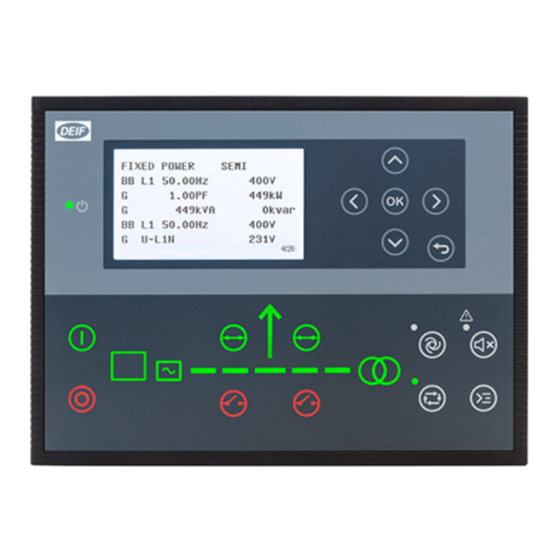
When PV power is added to a power management system (PMS), the application can include a maximum of two synchronising gensets. The PMS controls Genset 1 (G1) and Genset 2 (G2), and the genset breakers. The AGC 150 Hybrid controller is not part of the PMS. - Page 7 Name Function OFF: The controller power is OFF. Resolution: 240 x 128 px. Display screen* Viewing area: 88.50 x 51.40 mm. Six lines, each with 25 characters. Navigation Move the selector up, down, left and right on the screen. Go to the Menu system. Confirm the selection on the screen.
-
Page 8: Operating The System
3. Operating the system Mimic function Settings > Basic settings > Controller settings > Display > LED mimic Parameter no. Item Range Standard with genset Standard 6082 LED mimic Guided with genset Guided Standard The control buttons and LEDs are shown. If you stop the genset, the motor/generator symbols are not shown. -
Page 9: Running Modes
Running modes The controller has four running modes, and a test mode. To configure the running mode push the Shortcut button and select Running Modes. Configure the test mode in Settings > Power set points > Test. To run the test push the Shortcut button and select Start Test. -
Page 10: Hybrid Modes
The PV inverters supply as much of the load as possible. The genset operates at or at more than the minimum genset load. The AGC 150 Hybrid controller can control an application that combines PV power with genset power. It calculates the power set points for the PV power based on the genset power measurements. -
Page 11: Pv Amf (Automatic Mains Failure)
One AGC 150 Hybrid controller can control an application with a single genset, PV, and mains. The AGC 150 regulates the genset governor and AVR. It also controls the PV breaker and the mains breaker. For the genset regulation, you can use the AGC 150 analogue outputs. -
Page 12: Pv Lto (Load Take-Over)
PV LTO (Load take-over) The PV inverters supply the load to prevent/minimise import or export of power. Load bus Inverter (max. 16) Engine control Breaker feedback and control Inverter control Utility Start sequence in AUTO mode 1. The PV inverters supply the load. 2. -
Page 13: Pv Fixed Power
PV Fixed power In AUTO and SEMI-AUTO mode, the PV inverters supply the load configured in the set point for PV fixed power. If you start the generator, it supplies the load configured in the set point for general fixed power. Start sequence 1. -
Page 14: Pv Mpe (Mains Power Export)
PV MPE (Mains power export) In this mode a constant level of power through the mains breaker is maintained. The power can be exported to the mains or imported from the mains, but always at a constant level. This mode is also used when a fixed level of imported power is necessary. The set point can be set to 0 kW. - Page 15 • The genset supplies the load configured in the set point for minimum genset load. • If the load increases to more than the capacity of the PV inverters, the genset ramps up. • If the load increases to more than the capacity of the genset, the mains supplies the remaining load. Settings >...
-
Page 16: Pv Peak Shaving
PV Peak shaving The PV inverters supply the load. When the load is less than the peak shaving set point, the genset stops. If the load is more than the peak shaving set point, the genset starts. Load bus Inverter (max. -
Page 17: Menus
5. Menus Menu structure The controller has two menu systems, which can be used without password entry: • The View menu system: Shows the operating status and values. The system has 20 configurable windows, that can be entered with the arrow buttons. •... -
Page 18: Menu Numbers
5.2.1 Menu numbers Each parameter has a menu number. You can find the number in the upper right corner on the display screen. You can also find the menu number with the utility software: 1. Select Parameters from the vertical toolbar on the left. 2. -
Page 19: View Menu
View menu The view menu is shown when the controller is turned on, and you can see the operating status and values. The event and alarms list will also be shown if an alarm is on. 1. Operating status 2. Values and information 3. -
Page 20: Display Views
5.3.1 Display views The controller has 20 different display views, and 5 of the views are pre-configured. You can configure the views with the utility software. Line View 1 View 2 View 3 View 4 View 5 Supervision BB L1 0.0Hz 0V BB L1 0.0Hz 0V G U-L1L2 0V G L1 0.0Hz 0V... -
Page 21: Status Texts
3. Select the display line you want to change. 4. In the pop-up window, select the text you want and click OK. Display text You can select five of the display texts for each display view. Status texts Status text Condition ACCESS LOCK The configurable input is activated, and the operator tries to activate one of the blocked keys. - Page 22 Status text Condition DG BLOCKED FOR START The generator has stopped and has active alarm(s). EXT. START ORDER A planned AMF sequence is activated (without a mains failure). EXT. STOP TIME ###s The extended stop timer is running. FIXED POWER ACTIVE The controller is in auto mode and supplying fixed power.
-
Page 23: Service View
Status text Condition The power ramp is ramping in steps. The next step that is reached after the timer has expired is RAMP TO #####kW displayed. READY AMF AUTO The controller is in auto mode and the genset is stopped. READY FIXED P AUTO The controller is in auto mode and the genset is stopped. -
Page 24: Hybrid Shortcut Menu
Service view example Push Push 1/2O Push Push Hybrid shortcut menu You can start and stop the PV inverter in the shortcut menu when the controller is in SEMI-AUTO mode. On the controller 1. From the view menu, push the Shortcut button to see the menu. -
Page 25: Exhaust After-Treatment (Tier 4/Stage V)
Exhaust after-treatment (Tier 4/Stage V) AGC 150 supports Tier 4 (Final)/Stage V requirements. It provides monitoring and control of the exhaust after-treatment system, as required by the standard. AGC 150 Tier 4/Stage V screen ISLAND SEMI DEF level: 32.0% 1/20 Referent Symbol Description Engine emission system failure... - Page 26 Referent Symbol Description Page number Shows the number of the View menu screen. Engine interface status Shows a malfunction. Engine interface status Shows an engine shutdown. LIMIT lamp Only for MTU engines. Diesel Exhaust Fluid (DEF) Shows the fluid tank level is low. Diesel Exhaust Fluid (DEF) % level Shows the level (%) of the Diesel Exhaust Fluid.
-
Page 27: Alarm Handling And Log List
6. Alarm handling and log list Alarm handling If the function Alarm Jump is on, the controller will automatically show the alarm list on the display screen when an alarm occurs. Service View > Display > Alarm Jump Parameter Text Range Default 9157... -
Page 28: Logs Menu
CAUTION Caution If an alarm is blocking a genset in AUTO mode from starting, the genset will automatically start if the condition that triggered the alarm has gone and the alarm has been acknowledged. Logs menu These are the log sub-menus: 1.
Need help?
Do you have a question about the AGC 150 Hybrid and is the answer not in the manual?
Questions and answers