Table of Contents
Advertisement
Quick Links
Advertisement
Table of Contents
Troubleshooting

Related Manuals for Mitsubishi NZ2GF2B-60DA4


Summary of Contents for Mitsubishi NZ2GF2B-60DA4
-
Page 3: Safety Precautions
SAFETY PRECAUTIONS (Read these precautions before using this product.) Before using this product, please read this manual and the relevant manuals carefully and pay full attention to safety to handle the product correctly. The precautions given in this manual are concerned with this product only. For the safety precautions of the programmable controller system, refer to the user's manual for the CPU module used. - Page 4 [Design Precautions] CAUTION ● Do not install the control lines or communication cables together with the main circuit lines or power cables. Keep a distance of 100mm or more between them. Failure to do so may result in malfunction due to noise. ●...
- Page 5 To prevent this, configure an external safety circuit, such as a fuse. ● Mitsubishi programmable controllers must be installed in control panels. Wiring and replacement of a module must be performed by qualified maintenance personnel with knowledge of protection against electric shock.
- Page 6 [Startup and Maintenance Precautions] CAUTION ● After the first use of the product (terminal block), the number of connections/disconnections is limited to 50 times (IEC 61131-2 compliant). ● Before handling the module or the cable to be connected to the module, touch a conducting object such as a grounded metal to discharge the static electricity from the human body.
-
Page 7: Conditions Of Use For The Product
PRODUCT in one or more of the Prohibited Applications, provided that the usage of the PRODUCT is limited only for the specific applications agreed to by Mitsubishi and provided further that no special quality assurance or fail-safe, redundant or other safety features which exceed the general specifications of the PRODUCTs are required. -
Page 8: Introduction
When applying the program examples introduced in this manual to an actual system, ensure the applicability and confirm that it will not cause system control problems. Target module: NZ2GF2B-60DA4 Remark Unless otherwise specified, this manual describes the program examples in which the remote I/O signals and remote registers are assigned for a D/A converter module as follows. -
Page 9: Relevant Manuals
RELEVANT MANUALS (1) CC-Link IE Field Network (relevant) manuals When using the CC-Link IE Field Network for the first time, refer to CC-Link IE Field Network Master/Local Module User's Manual first. The following shows the structure of the CC-Link IE Field Network manuals. Manual name Description <manual number (model code)>... -
Page 10: Table Of Contents
CONTENTS CONTENTS SAFETY PRECAUTIONS ............. 1 CONDITIONS OF USE FOR THE PRODUCT . - Page 11 CHAPTER 7 VARIOUS SETTINGS Parameter Setting............Changing the Parameter.
- Page 12 Appendix 4 I/O Conversion Characteristic of D/A Conversion ......Appendix 5 Accuracy of D/A Conversion ..........Appendix 6 Conversion Speed of D/A Conversion.
-
Page 13: Manual Page Organization
MANUAL PAGE ORGANIZATION In this manual, pages are organized and the symbols are used as shown below. The following illustration is for explanation purpose only, and should not be referred to as an actual documentation. "" is used for screen names and items. The chapter of the current page is shown. -
Page 14: Term
TERM Unless otherwise specified, this manual uses the following terms. Term Description CC-Link IE Field Network A high-speed and large-capacity open field network that is based on Ethernet (1000BASE-T) D/A converter module Another term for the CC-Link IE Field Network D/A converter module GX Works2 The product name of the software package for the MELSEC programmable controllers REMFR... - Page 15 Term Description A module with the CC-Link IE Field Network communication function, which can be used as a single Main module remote module. Extension modules can be connected to this module. Dedicated instruction An instruction that simplifies programming for using functions of intelligent function modules A remote module that does not support the CC-Link IE Field Network communication function.
-
Page 16: Packing List
PACKING LIST The following items are included in the package of this product. Before use, check that all the items are included. D/A converter module Module Before Using the Product... -
Page 17: Chapter 1 D/A Converter Module
CHAPTER 1 D/A CONVERTER MODULE CHAPTER 1 D/A CONVERTER MODULE This chapter describes the applications and features of the D/A converter module. Application This module converts the digital data to the analog signal and outputs it to the external devices. Digital to analog Analog signal (continuous signal) conversion... -
Page 18: Features
Features (1) Available flexible system configuration Adopting the connection block type enables the combination of the main module and extension module. Because various extension modules can be connected, a flexible configuration can be achieved. In addition a poor contact of the extension module can be found promptly because the main module always monitors the connection status of the extension module. - Page 19 CHAPTER 1 D/A CONVERTER MODULE (6) Error detection and monitoring available When a digital value exceeds the range set in advance, an alert is detected. Thus, an error of digital value can be monitored and outputs of a digital value can be limited. (7) Output available without influence from the sequence scan or link scan An error status or alert status can be output from the extension output module by using the external signal assignment function when an error or alert occurs.
- Page 20 (9) Easy module replacement Because the 2-piece structure is adopted for the terminal block for module power supply and FG and terminal block for analog output signals, the module can be replaced with the wire connected. In addition, because the terminal block for analog output signals is the lift-up structure, the terminal block can be lifted only by loosening the terminal block mounting screw to be removed easily.
-
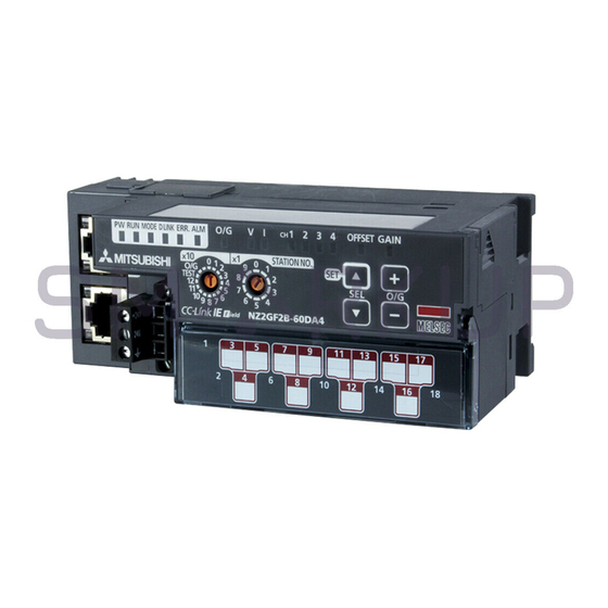
Page 21: Chapter 2 Part Names
CHAPTER 2 PART NAMES CHAPTER 2 PART NAMES The section describes part names of the D/A converter module. 7) 8) *1 Do not remove this seal because it is used for a maintenance purpose. Name Application A rotary switch for the following setting and test. •... - Page 22 Name Application PW LED (green) Indicates the operating status of the D/A converter module. Power supply ON Power supply OFF RUN LED (green) Indicates the operating status of the D/A converter module. Operating normally. Writing data to the nonvolatile memory in the offset/gain setting mode. A major error has occurred or in the offset/gain setting mode.
- Page 23 CHAPTER 2 PART NAMES Name Application PORT1 connector for CC-Link IE Field Network (RJ45 connector) Connect an Ethernet cable. ( Page 54, Section 6.5) There are no restrictions on the connection order of the cables for the "P1" connector and "P2" connector. •...
- Page 24 (1) Module status and LED status The following table lists the correspondence between the module status and the LED status. LED status Data link Module status MODE D LINK ERR. status Disconnecting Disconnection Data link in Link in progress operation Normal mode Reserved station specification in...
-
Page 25: Chapter 3 Specifications
Do not use or store the D/A converter module under pressure higher than the atmospheric pressure of altitude 0m. Doing so may cause malfunction. When using the D/A converter module under pressure, please consult your local Mitsubishi representative. If the environment satisfies the operating ambient temperature, operating ambient humidity and other conditions, the module can be used even outside the control panel. - Page 26 To use the D/A converter module complying with the EMC Directive, refer to "EMC and Low Voltage Directives" in this manual. ( Page 156, Appendix 7)
-
Page 27: Performance Specifications
CHAPTER 3 SPECIFICATIONS Performance Specifications Item Description Number of analog output points 4 points (4 channels)/module Digital input 16-bit signed binary (-16384 to 16383, -288 to 12287, -12288 to 12287) Voltage -10 to 10VDC (external load resistance value: 1kΩ to 1MΩ) Analog output Current 0 to 20mADC (external load resistance value: 0Ω... - Page 28 Item Description TE 0.5-10 (Nichifu Co. Ltd.) [Applicable wire size: 0.5mm TE 0.75-10 (Nichifu Co. Ltd.) [Applicable wire size: 0.75mm TE 1.0-10 (Nichifu Co. Ltd.) [Applicable wire size: 0.9 to 1.0mm Terminal block TE 1.5-10 (Nichifu Co. Ltd.) [Applicable wire size: 1.25 to 1.5mm for module AI 0.34-12TQ (Phoenix Contact Co.
-
Page 29: Calculating Current Consumption
The value of the module power supply current in the extension module described in the specifications is the value of the module power supply current supplied from the main module. D/A converter module Extension module NZ2GF2B-60DA4 NZ2EX2B1-16T 355mA Module power supply current:... -
Page 30: Function List
Function List Item Description Reference Whether to enable or disable D/A conversion can be set for each channel. Page 74, D/A conversion enable/disable function Disabling the D/A conversion for unused channels reduces the Section 8.1 conversion cycles. Whether to output the D/A conversion value or the offset value can be set for each channel. -
Page 31: List Of Remote I/O Signals
CHAPTER 3 SPECIFICATIONS List of Remote I/O Signals This section lists I/O signals for a master/local module. The device numbers shown are the example with the remote I/O signals of the main module assigned to the I/O numbers of RX0 to RX1F and RY0 to RY1F. Remote input (RX) indicates the input signal from the D/A converter module to the master/local module. - Page 32 Remote input Remote output signal direction: D/A converter module → signal direction: Master/local module → Module Master/local module D/A converter module type Device Device Description Description number number RX10 Use prohibited RY10 CH1 Output enable/disable flag RX11 Use prohibited RY11 CH2 Output enable/disable flag RX12 Use prohibited...
-
Page 33: List Of Remote Register
CHAPTER 3 SPECIFICATIONS List of Remote Register This section lists remote registers for a master/local module. The remote registers shown are the example with the remote registers of the main module assigned to the remote registers of RWr0 to RWrF and RWw0 to RWwF. Remote register (RWr) is the information input from the D/A converter module to the master/local module. -
Page 34: List Of Remote Buffer Memory
List of Remote Buffer Memory This section lists the remote buffer memory areas of the D/A converter module. The remote buffer memory areas of the main module and extension module are assigned as shown below. Main module Extension module 1 Example of the remote buffer memory in the manual D/A conversion enable/disable setting (address: 0102 Address of a D/A converter module... - Page 35 CHAPTER 3 SPECIFICATIONS For the REMFR and REMTO instructions, refer to the following. User's manual for the master/local module used For the access method, refer to the following. • Parameter area ( Page 63, Section 7.1) • Error history area ( Page 116, Section 11.1 Do not access the system area using the REMFR or REMTO instruction.
- Page 36 Address Type Description Default Read/Write Decimal Hexadecimal 0100 256, System area 0101 0102 000F D/A conversion enable/disable setting 0103 0000 Range setting 0104 0000 Analog output HOLD/CLEAR setting 0105 000F Alert output setting Module-based 0106 0000 CH1 Alert output upper limit value parameter data 0107 0000...
- Page 37 CHAPTER 3 SPECIFICATIONS (a) Parameter area of the extension module The remote buffer memory differs depending on the model of the extension module. • Extension input module (NZ2EX2B1-16D) Address Description Default Read/Write Decimal Hexadecimal 0200 0000 Extension module identification code 0201 System area 02FF...
- Page 38 (2) Monitoring area (address: 0500 to 09FF Address Type Description Default Read/Write Decimal Hexadecimal 0500 1280 Station-based System area monitoring data 1535 05FF 0600 Module-based 1536 monitoring data System area (main module) 1791 06FF Module-based 0700 1792 monitoring data The remote buffer memory of the connected (extension extension module is assigned.
- Page 39 CHAPTER 3 SPECIFICATIONS Address Description Default Read/Write Decimal Hexadecimal 0714 1812 Number of ON times integration value Y2 1813 0715 0716 1814 Number of ON times integration value Y3 1815 0717 0718 1816 Number of ON times integration value Y4 1817 0719 071A...
- Page 40 (3) Error history area (address: 0A00 to 0FFF Address Type Description Default Read/Write Decimal Hexadecimal 0A00 0000 2560 Error code 0A01 0000 2561 Order of generation [Error time] First two digits 0A02 0000 2562 of the year/Last two digits of the year 0A03 0000 2563...
- Page 41 CHAPTER 3 SPECIFICATIONS Address Type Description Default Read/Write Decimal Hexadecimal 0AB0 2736 Error history 12 Same as Error history 1. 2751 0ABF 0AC0 2752 Error history 13 Same as Error history 1. 2767 0ACF 0AD0 2768 Station-based Error history 14 Same as Error history 1.
- Page 42 (a) Module control data area of the extension module The remote buffer memory differs depending on the model of the extension module. • Extension input module Address Description Default Read/Write Decimal Hexadecimal 1200 4608 System area 4863 12FF This is the value for when the module power supply is turned off and on or at the remote reset. This shows whether read or write from programs is possible.
-
Page 43: Chapter 4 The Procedure Before Operation
CHAPTER 4 THE PROCEDURE BEFORE OPERATION CHAPTER 4 THE PROCEDURE BEFORE OPERATION This section describes the procedure before operation. Check box Setting a station number Page 45, Section 6.1 Set the station number for an D/A converter module. Connection Page 46, Section 6.2, When using an extension module, connect the extension module to the Page 48, Section 6.3 D/A converter module. - Page 44 Memo...
-
Page 45: Chapter 5 System Configuration
CHAPTER 5 SYSTEM CONFIGURATION CHAPTER 5 SYSTEM CONFIGURATION This chapter describes system configuration using a D/A converter module. For CC-Link IE Field Network configuration, refer to the following. User's manual for the master/local module used D/A Converter Module System Configuration The following shows system configuration using a D/A converter module. -
Page 46: Applicable Systems
Applicable Systems (1) Applicable master station When using a D/A converter module, use the following products as a master station. Model First five digits of serial number QJ71GF11-T2 "14102" or later LJ71GF11-T2 When a master station other than the above is used, the D/A converter module cannot be used. (2) Connectable modules One extension module can be connected to one D/A converter module. -
Page 47: Chapter 6 Installation And Wiring
CHAPTER 6 INSTALLATION AND WIRING CHAPTER 6 INSTALLATION AND WIRING This chapter describes the installation and wiring of the D/A converter module. Station Number Setting (1) Setting procedure Set the station number with the rotary switch on the front of the module. The setting value of the station number becomes valid when the module is powered on. -
Page 48: Installation Environment And Installation Position
Installation Environment and Installation Position 6.2.1 Installation environment (1) Installation location Do not install the D/A converter module to the place where: • Ambient temperature is outside the range of 0 to 55°C; • Ambient humidity is outside the range of 5 to 95% RH; •... -
Page 49: Installation Direction
CHAPTER 6 INSTALLATION AND WIRING 6.2.3 Installation direction The D/A converter module can be installed in six directions. Use the DIN rail to install the module. Downward installation DIN rail Horizontal installation Vertical installation Horizontal installation (upside down) Upward installation... -
Page 50: Installation
Installation 6.3.1 Connecting extension modules (1) Connecting procedure Remove the cover on the side of the module. Do not dispose the removed cover, but store it. Release the module joint levers (two points) on the side of the extension module. Slide the levers vertically. -
Page 51: Mounting The Modules On A Din Rail
CHAPTER 6 INSTALLATION AND WIRING 6.3.2 Mounting the modules on a DIN rail An example of the use of the DIN rail stopper is described in the following procedure. Fix the module according to the manual of the DIN rail stopper used. (1) Mounting procedure Pull down all DIN rail hooks on the back of the modules. - Page 52 Hitch the upper hook of the DIN rail stopper to the Hitch the hook to top of the DIN rail. top of the DIN rail Slide the DIN rail stopper up to the left side of the DIN rail modules. stopper Hold the DIN rail stopper in the direction opposite to DIN rail...
- Page 53 CHAPTER 6 INSTALLATION AND WIRING (4) Interval between DIN rail mounting screws Tighten the screws at intervals of 200mm or less. (5) DIN rail stopper Use a stopper that is attachable to the DIN rail.
-
Page 54: Wiring With Terminal Block For Module Power Supply And Fg
Wiring with Terminal Block for Module Power Supply and FG (1) Tightening torque Tighten the terminal block screws within the following specified torque range. Tightening the screws too much may damage the module case. Screw type Tightening torque range Terminal block mounting screw (M2.5 screw) 0.2 to 0.3N•m Terminal screw (M2.5 screw) 0.5 to 0.6N•m... - Page 55 CHAPTER 6 INSTALLATION AND WIRING (4) Connecting and disconnecting the cable To connect the cable, insert the wire with the cable fixing screw loosened and tighten the screw. To disconnect the cable, pull out the wire with the cable fixing screw loosened with a slotted screwdriver. (5) Processing method of the cable terminal Strip the cable about 10mm from the top.
-
Page 56: Wiring Of Ethernet Cable
Wiring of Ethernet Cable (1) Connecting the Ethernet cable (a) Connecting Power off the power supplies of the D/A converter module and the external device. Push the Ethernet cable connector into the D/A converter module until it clicks. Pay attention to the connector's direction. - Page 57 CHAPTER 6 INSTALLATION AND WIRING ● PORT1 and PORT2 need not to be distinguished. When only one connector is used in star topology, either PORT1 or PORT2 can be connected. Either one can be used. ● When two connectors are used in line topology or ring topology, an Ethernet cable can be connected to the connectors in any combination.
- Page 58 (2) Precautions (a) Laying Ethernet cables • Place the Ethernet cable in a duct or clamp them. If not, dangling cable may swing or inadvertently be pulled, resulting in damage to the module or cables or malfunction due to poor contact. •...
-
Page 59: Wiring Of External Device And Terminal Block
CHAPTER 6 INSTALLATION AND WIRING Wiring of External Device and Terminal Block (1) Tightening torque Tighten the terminal block screws within the following specified torque range. Failure to secure the terminal block may cause malfunction, failure, or drop. Screw type Tightening torque range Terminal screw (M3 screw) 0.43 to 0.57N•m... - Page 60 (b) Installation procedure Open the terminal block cover to install the 2-piece terminal block. Tighten the terminal block mounting screws. Terminal block mounting screw...
- Page 61 CHAPTER 6 INSTALLATION AND WIRING (3) Wiring of the external device and terminal block (a) Signal name The following shows signal names of the terminal block. Pin number Signal name Do not wire the NC terminals. Wrong wiring may cause the module to fail or malfunction.
- Page 62 (b) Wiring to a terminal block The following shows wirings to a terminal block. • For the voltage output • For the current output...
- Page 63 CHAPTER 6 INSTALLATION AND WIRING (c) Precautions for external wiring To obtain the maximum performance from the functions of the D/A converter module and improve the system reliability, an external wiring with high durability against noise is required. Precautions for external wiring are as follows: •...
- Page 64 (e) Wiring method Loosen the terminal screw. Connect the round Self-tightening screw solderless terminal as it is. is used Round solderless terminal ● Do not put oil on the terminal and screw. Failure to do so may damage the screw. ●...
-
Page 65: Chapter 7 Various Settings
CHAPTER 7 VARIOUS SETTINGS CHAPTER 7 VARIOUS SETTINGS This chapter describes the setting procedures of the D/A converter module. Parameter Setting Set the parameter of this module with the network parameter written to the CPU module of the master station. When the setting in GX Works2 and the parameter written to the CPU module do not match, the parameter cannot be written and read. - Page 66 Display the "CC IE Field Configuration" window. • When the master/local module is the QJ71GF11-T2 Project window [Parameter] [Network Parameter] [Ethernet/CC IE/MELSECNET] button • When the master/local module is the LJ71GF11-T2 Project window [Parameter] [Network Parameter] [CC IE Field] button Select the D/A converter module in "List of stations"...
- Page 67 CHAPTER 7 VARIOUS SETTINGS Double-click the item to change the setting, and input the setting value. • Items to input from the pull-down list Double-click the item to set, to display the pull-down list. Select the item. • Items to input from the text box Double-click the item to set, and input the setting value.
- Page 68 Item Reference Alert output signal assignment External signal assignment Error flag assignment Page 99, Section 8.11 (3) setting Warning flag assignment Cyclic data update watch time setting Page 78, Section 8.5 Input response time setting Extension I/O setting Page 98, Section 8.11 (1) Digital output HOLD/CLEAR setting CH1 D/A conversion enable/disable setting CH2 D/A conversion enable/disable setting...
- Page 69 CHAPTER 7 VARIOUS SETTINGS ● When using the extension module, also set the parameter of the extension module. For the parameter of the extension module, refer to the following. Manual for the extension module used ● Set all the items for the parameter. If any blank exists, the parameter cannot be written to the D/A converter module. ●...
-
Page 70: Changing The Parameter
Changing the Parameter 7.2.1 Changing the network configuration When changing the network configuration diverting the created project, set the parameter in the following procedure. Power off the module. Connect the modules again according to the desired network configuration. Power on the module. Display the "CC IE Field Configuration"... - Page 71 CHAPTER 7 VARIOUS SETTINGS Set the refresh parameter. Change the value as necessary. Write the set parameter to the CPU module of the master station and reset the CPU module. RESET Change the status of the CPU module of the master station to RUN. The network configuration setting is now completed.
-
Page 72: Changing The Parameter Without Changing The Network Configuration
7.2.2 Changing the parameter without changing the network configuration To change only the created module parameter of the slave station without changing the network configuration, set the parameter in the following procedure. Display the "CC IE Field Configuration" window. • When the master/local module is the QJ71GF11-T2 Project window [Parameter] [Network Parameter]... - Page 73 CHAPTER 7 VARIOUS SETTINGS Set "Parameter write" for "Method selection". Check the read parameter and select the item to be changed from "Write Value". Then set a new value. For the item not to be changed, set the same value as "Read Value" for "Write Value". Click the button to write the parameter to the D/A converter module.
-
Page 74: Offset/Gain Setting
Offset/Gain Setting When the user range setting is used, configure the offset/gain setting with the following operations. When factory default settings are used, the offset/gain setting is not required. Power off the module. Set "O/G" for "x10" of the station number setting switch. - Page 75 CHAPTER 7 VARIOUS SETTINGS ● Configure the offset/gain setting in accordance with the actual use situation. Connection to the CC-Link IE Field Network is not required. ● Configure the offset/gain setting in the range satisfying the following condition. When the setting value out of the range is configured, the maximum resolution and accuracy of the module may not fall within the range shown in the following performance specifications.
-
Page 76: Chapter 8 Function
CHAPTER 8 FUNCTION This chapter describes the details of the functions available in the D/A converter module, and the setting procedures for those functions. For details on remote I/O signals, remote registers, and remote buffer memory, refer to the following. •... -
Page 77: Range Switching Function
CHAPTER 8 FUNCTION Range Switching Function The output range can be selected for each channel from the following ranges: • Factory default range (4 to 20mA, 0 to 20mA, 1 to 5V, 0 to 5V, -10 to 10V) • User range (user range setting 1, user range setting 2) (1) Setting procedure Set "Parameter write"... -
Page 78: Analog Output Hold/Clear Function
Analog Output HOLD/CLEAR Function Whether to hold or clear the output analog value can be set, according to the CPU module operating status (RUN, STOP, or stop error). (1) Combination of analog output status The following table shows how the analog output status changes, depending on the combination of settings for D/A conversion enable/disable setting (address: 0102 ) and CH Output enable/disable flag (RY10 to RY13). - Page 79 CHAPTER 8 FUNCTION (2) Setting procedure Set "Parameter write" for "Method selection". "CC IE Field Configuration" window Select a D/A converter module in "List of stations" [CC IE Field Configuration] [Parameter Processing of Slave Station] Set "CH D/A conversion enable/disable setting" to "0: Enable". Set "CH Analog output HOLD/CLEAR setting".
-
Page 80: Cyclic Data Update Watch Function
Cyclic Data Update Watch Function The update intervals of cyclic data are monitored. The last output value is held or cleared when the cyclic transmission stop status continues longer than the set monitoring time. The cyclic transmission stop status is the status that the D LINK LED is flashing (Data link in operation (cyclic transmission stopped)) or off (Data link not performed (disconnected)). -
Page 81: Scaling Function
CHAPTER 8 FUNCTION Scaling Function The D/A converter module scale-converts the digital value to the set range of the scaling upper limit value and scaling lower limit value. The programming for scale conversion can be reduced. (1) Concept of scaling setting The setting for scaling lower and upper limit values differs depending on whether the factory default setting or the user range setting is used for the analog output range. - Page 82 (3) Setting procedure Set "Parameter write" for "Method selection". "CC IE Field Configuration" window Select a D/A converter module in "List of stations" [CC IE Field Configuration] [Parameter Processing of Slave Station] Set "CH D/A conversion enable/disable setting" to "0: Enable". Set "CH Scaling enable/disable setting"...
- Page 83 CHAPTER 8 FUNCTION (4) Example of scaling setting 1: When values are set for a channel with output range of 0 to 5V as follows: • "CH Scaling enable/disable setting": "0: Enable" • "CH Scaling upper limit value": 10000 • "CH Scaling lower limit value": 2000 The digital values and scale-converted digital values are as follows: Analog output voltage (V)
- Page 84 2: When values are set for a channel with output range of -10 to 10V as follows: • "CH Scaling enable/disable setting": "0: Enable" • "CH Scaling upper limit value": 12000 • "CH Scaling lower limit value": 4000 The digital values and scale-converted digital values are as follows: Analog output voltage (V) -10V -16384...
- Page 85 CHAPTER 8 FUNCTION 3: When values are set for a channel with the user range 1 of 2 to 10V as follows: • "CH Scaling enable/disable setting": "0: Enable" • "CH Scaling upper limit value": 8000 • "CH Scaling lower limit value": 2000 The digital values and scale-converted digital values are as follows: Analog output voltage (V) -12288...
- Page 86 ● When using the scaling function, the digital value before scaling can be set to a value out of the range of the scaling upper and lower limit values (dotted line area in the I/O characteristics). However, use the scaling function within the range of the analog output practical range (solid line area in the I/O characteristics).
-
Page 87: Shift Function
CHAPTER 8 FUNCTION Shift Function Using this function, the D/A converter module outputs the converted digital value with the shifting set value added, in analog. When the shifting set value is changed, it is reflected to the analog output value in real time. Therefore, fine adjustment can be easily performed when the system starts. - Page 88 Set a value for CH Shifting set value (RWw6 to RWw9). The default value of the shifting set value is "0". Item Setting range Shifting set value (RWw6 to RWw9) -32768 to 32767 If the digital value exceeds the range of -32768 to 32767 as a result of shift addition, the digital operation value is fixed to the lower limit value (-32768) or the upper limit value (32767).
- Page 89 CHAPTER 8 FUNCTION (4) Setting example of when both the scaling function and shift function are used When the following settings are used for a channel with output range of 0 to 5V: • "CH Scaling enable/disable setting": "0: Enable" •...
- Page 90 Set "Parameter write" for "Method selection". "CC IE Field Configuration" window Select a D/A converter module in "List of stations" [CC IE Field Configuration] [Parameter Processing of Slave Station] Set "CH D/A conversion enable/disable setting" to "0: Enable". Set "CH Scaling enable/disable setting"...
-
Page 91: Digital Value Range Check Function
CHAPTER 8 FUNCTION Digital Value Range Check Function An error is output when the digital value is out of the digital input range for the output range. (1) Notification of a check code When the digital value is greater than the upper limit of the setting range or smaller than the lower limit of the setting range, it is notified with the following operation. - Page 92 (3) Resetting a check code The check codes can be reset by either of the following two methods. • Write a digital value within the setting range, and turn on and off Error clear request flag (RYA). • Turn on and off Initial data setting request flag (RY9). (4) When the scaling function is set enabled When Scaling enable/disable setting (address: 010E ) is set to Enable (0), the scale-converted digital value is...
- Page 93 CHAPTER 8 FUNCTION (6) Operation example of the check code detection When values are set for a channel with output range of -10 to 10V as follows: • "CH Scaling enable/disable setting": "0: Enable" • "CH Scaling upper limit value": 24000 •...
-
Page 94: Alert Output Function
Alert Output Function This function outputs alert when a digital value is in the range set in advance. Digital value Digital value Analog output value Alert output upper limit value 10000 Alert output lower limit value -1000 Alert output flag (CH1 upper limit value) (RWrA. - Page 95 CHAPTER 8 FUNCTION (1) Alert output notification When the digital value is greater than the alert output upper limit value, or smaller than the alert output lower limit value, alert notifications are made by Alert output flag (RWrA), Alert output signal (RX1E) and the ALM LED turning ON.
- Page 96 (5) When the shift function is set enabled When a value is set to CH Shifting set value (RWw6 to RWw9), the value with the shifting set value added is the target for the alert. (6) Setting procedure Set "Parameter write" for "Method selection". "CC IE Field Configuration"...
-
Page 97: Error Notification Function
CHAPTER 8 FUNCTION 8.10 Error Notification Function When an error, warning, or alarm occurs, the D/A converter module notifies the master station of it using remote input signals and remote registers. Remark The notification of the error, warning, or alarm can be checked on the LED on the front of the module. For details, refer to the following. - Page 98 A warning is in the following state five seconds after the error cause is removed. • Warning flag (RX7) turns off. • Latest warning code (RWr1) is cleared. • The ERR. LED turns off. The alarm is not automatically cleared. Latest warning code (RWr1) is cleared when the other minor errors are cleared in the alarm status.
- Page 99 CHAPTER 8 FUNCTION (3) Method for clearing an error by executing the command of the slave station The following shows how to clear an error by executing the command of the slave station. Moderate errors and Out-of-range digital value can be cleared. Select the D/A converter module in "List of stations"...
-
Page 100: Function At The Extension Module Installation
8.11 Function at the Extension Module Installation One extension I/O module can be connected to one D/A converter module. Remote input signals of the D/A converter module can be assigned to remote output signals of the connected extension output module. In addition, functions unique to the extension I/O module can be used. ●... - Page 101 CHAPTER 8 FUNCTION (3) External signal assignment function Remote output signals of the D/A converter module can be assigned to output signals of the connected extension output module. Error signals can be output to the external from the extension output module at the fixed timing without influence from the sequence scan or link scan.
- Page 102 (4) Setting procedure When setting the assignment explained in the previous page Set "Parameter write" for "Method selection". "CC IE Field Configuration" window Select a D/A converter module in "List of stations" [CC IE Field Configuration] [Parameter Processing of Slave Station] Set "CH D/A conversion enable/disable setting"...
- Page 103 CHAPTER 8 FUNCTION (a) Operation of when an error occurs The operation of the D/A converter module for an error depends on whether or not the external signal assignment function is used, as show in the following table. Remote I/O signal Remote input (RX) Remote output (RY) Digital output HOLD/CLEAR...
-
Page 104: Cc-Link Ie Field Network Diagnostic Function
8.12 CC-Link IE Field Network Diagnostic Function With this function, whether any network error occurs or not can be checked through GX Works2 connected to the CPU module. (1) How to use Connect GX Works2 to the CPU module. Start CC-Link IE Field Network diagnostics from the menu of GX Works2. [Diagnostics] [CC IE Field Diagnostics]... - Page 105 CHAPTER 8 FUNCTION Item to be diagnosed Description Reference Display of network The status of the CC-Link IE Field Network can be checked. configuration diagram and When an error or warning for the D/A converter module occurs, the status of error status the station is displayed on an icon.
- Page 106 (a) Remote operation Select a slave station to be reset and click the button. Clicking the button on the following window starts the remote reset. Click the button on the following window.
-
Page 107: Chapter 9 Programming
CHAPTER 9 PROGRAMMING CHAPTER 9 PROGRAMMING This chapter describes the programming of the D/A converter module. Precautions for Programming This section describes precautions to create CC-Link IE Field Network programs. (1) Cyclic transmission program For a cyclic transmission program, interlock with the following link special relay (SB) and link special register (SW). -
Page 108: Procedure For Programming
Program Example (1) System configuration Power supply module (Q62P) CPU module (Q10UDHCPU) Master/local module (QJ71GF11-T2) Input module (QX10) D/A converter module (NZ2GF2B-60DA4) Extension output module (NZ2EX2B1-16T) 00 to 1F 20 to 2F Master station (Station No.0) RY20: Error flag (assignment) - Page 109 CHAPTER 9 PROGRAMMING (a) Link device assignment Master station (Station No.0) Remote device station (Station No.1) Master/local Main module Extension module CPU module module (D/A converter module) (extension output module) RX0 to RX9, RXB to RX1D, RX00 X1000 RX1F RX0F X100F RXA Error flag RX1E Alert output signal...
- Page 110 (2) Programming condition This program enables the D/A conversion in CH1 and CH2 of the D/A converter module and outputs the written digital values in analog. If an error or alert occurs, a digital signal is output from the extension output module. (3) Initial setting description Setting item Setting value...
- Page 111 Batch analog output enable command Alert output clear command QX10 (X20 to X2F) Error clear command Check code clear command X1007 Warning flag X1009 Initial data setting completed flag NZ2GF2B-60DA4 X100A Error flag (X1000 to X101F) X100B Remote READY X101E Alert output signal Y100A...
- Page 112 (5) Setting procedure Connect GX Works2 to the master station to configure the setting. Create a project on GX Works2. Select "QCPU (Q mode)" for "PLC Series" and select "Q10UDH" for "PLC Type". [Project] [New] Display the network parameter setting window and configure the setting as follows. Project window [Parameter] [Network Parameter]...
- Page 113 CHAPTER 9 PROGRAMMING Display the "CC IE Field Configuration" window and configure the configuration and station number of the slave station as follows. button Close the "CC IE Field Configuration" window. [CC IE Field Configuration] [Close with Reflecting the Setting] Display the refresh parameter setting window and configure the setting as follows.
- Page 114 Display the "Parameter Processing of Slave Station" window and change "Method selection" to "Parameter write" to set the following. Project window [Parameter] [Network Parameter] [Ethernet/CC IE/MELSECNET] button Select a D/A converter module in "List of stations" [CC IE Field Configuration] [Parameter Processing of Slave Station] Click the button to write the parameter to the D/A converter module.
- Page 115 CHAPTER 9 PROGRAMMING (6) Program example Create the following program with GX Works2. CH1 Digital value setting CH2 Digital value setting CH1 Output enable/disable flag CH2 Output enable/disable flag Check the alert output. Check CH1 Digital value range. Check CH2 Digital value range. CH2 Alert output processing CH2 Processing at the alert occurrence (upper limit value) (upper limit)
-
Page 116: Chapter 10 Maintenance And Inspection
CHAPTER 10 MAINTENANCE AND INSPECTION The D/A converter module has no special item to be inspected. However, to maintain the best condition of the system, perform the inspection in accordance with the items described in the user's manual of the CPU module used. - Page 117 CHAPTER 10 MAINTENANCE AND INSPECTION Memo...
-
Page 118: Chapter 11 Troubleshooting
CHAPTER 11 TROUBLESHOOTING This chapter describes errors that may occur while the D/A converter module is used, and those troubleshooting. 11.1 Checking for the Error Codes and the Alarm Codes Error codes can be checked by any of the following methods: •... - Page 119 CHAPTER 11 TROUBLESHOOTING When the window shown on the left is displayed, click the button. The error history of the D/A converter module is displayed in "Execution Result". Item Contents Error code The action for the error is displayed. Order of generation The order of error occurrence is displayed.
- Page 120 (2) Checking by Latest error code (RWr0) Check the latest error code with the buffer memory of the master/local module. [Online] [Monitor] [Device/Buffer Memory Batch] When the refresh target device for Latest error code (RWr0) is W1100 (3) Checking by Latest warning code (RWr1) Check the latest warning code with the buffer memory of the master/local module.
-
Page 121: Error Code List
Hardware If this error persists, the module may be in 0010 Major error Module hardware error failure failure. Please consult your local Mitsubishi representative. The value set in Range setting (address: 0103 ) is outside the Range setting Set the value of Range setting (address:... - Page 122 • Take measures against noise with a (parameter) shielded cable for connection. • If this error persists, the module may be in failure. Please consult your local Mitsubishi representative. • The module will be automatically recovered immediately after the error occurs. Note...
- Page 123 Moderate error outside the even after measures have been taken against CPU module is invalid. range noise, please consult your local Mitsubishi representative. Take measures against noise and reset the Network No. module. If the same error occurs again, the...
- Page 124 2 the module may be in failure. Please consult your local Mitsubishi representative. Set a value within the allowable range. Then perform one of the following operations to clear the error. • Turn on and off Error clear request flag (RYA).
- Page 125 CHAPTER 11 TROUBLESHOOTING (2) Error code list (D000 to DFFF (D529 and D52B excluded)) When an error occurs, the ERR. LED does not turn on. The D LINK LED flashes or turns off. Troubleshoot the problem with the CC-Link IE Field Network diagnostics. ( Page 102, Section 8.12) Error code Error name...
-
Page 126: Alarm Code List
11.3 Alarm Code List This section lists alarm codes. Alarm code Category Name Description and cause of alarm Action (hexadecimal) An alert is occurring. The channel where the alert has occurred fits in Set again the digital value within the setting Alert Minor error range, and turn on and off Alert output clear... -
Page 127: Checking The Leds
When any LED other than the PW LED turns on, the possible cause is a Is any LED other than the PW LED turned on? hardware failure. Please consult your local Mitsubishi representative. Is the module power supply (24VDC) wired? Wire the module power supply (24VDC). - Page 128 (5) When the D LINK LED turns off Check item Action Connect GX Works2 to the master station, and check if the own station is performing data link by CC-Link IE Field Network diagnostics. Does the own station in network operate normally? User's manual for the master/local module used) Replace the cable with a 1000BASE-T-compliant Ethernet cable.
- Page 129 CHAPTER 11 TROUBLESHOOTING (7) When the L ER LED turns on Check item Action • Check if 1000BASE-T-compliant Ethernet cables are used. User's manual for the master/local module used) Are Ethernet cables normal? • Check if the station-to-station distance is 100m or less. •...
-
Page 130: Unit Test
If the test fails again, it may be due to a hardware failure in the D/A converter module. Please consult your local Mitsubishi representative. Remark When unit test fails, the error details can be checked in the error history in GX Works2. -
Page 131: Troubleshooting For Each Phenomenon
When the output is performed properly, check the program again. If the analog output value cannot be output even after the above actions are taken, the D/A converter module may be failed. Please consult your local Mitsubishi representative. (2) When the analog output value is not held... - Page 132 (3) When the ON/OFF status of the remote output (RY) set in the external signal assignment function does not match the signal of the assigned function. Check item Action Check that the following settings are not used in the external signal assignment function.
-
Page 133: Appendices
APPENDICES APPENDICES Appendix 1 Details of Remote I/O Signals This section describes the details of remote I/O signals assigned to the master/local module. The assignment of each device number is for the case when the remote I/O signals of the main module are assigned as follows. - Page 134 (2) Initial data setting completed flag (RX9) Turn on Initial data setting request flag (RY9) after writing parameter data to the remote buffer memory with the REMTO instruction. This signal turns on when the operating condition is changed. When the following settings are changed, the signal is used as an interlock condition to turn Initial data setting request flag (RY9) on and off.
- Page 135 APPENDICES (3) Error flag (RXA) This signal turns on when a moderate or major error occurs. To clear Latest error code (RWr0), turn on and off Error clear request flag (RYA). • When a moderate error occurs Controlled by the D/A converter module Controlled by the program Error 0000...
- Page 136 (4) Remote READY (RXB) This signal is used as an interlock condition when the master station reads/writes data to/from the remote register or remote buffer memory areas of the D/A converter module. The signal turns on when the module power supply is turned on. When Error flag (RXA) turns on, the signal turns off.
-
Page 137: Appendix 1.2 Remote Output Signals
APPENDICES Appendix 1.2 Remote output signals (1) Initial data setting request flag (RY9) Turn on this signal after writing parameter data to the remote buffer memory. Initial data setting completed flag (RX9) turns on when the operating condition is changed. For the on and off timing, refer to the following. -
Page 138: Appendix 2 Details Of Remote Register Areas
Appendix 2 Details of Remote Register Areas This section describes the details of remote register areas for communications with the master/local module. The assignment of each device number is for the case when the remote registers of the main module are assigned to RWr0 to RWrF and RWw0 to RWwF. - Page 139 APPENDICES (a) Resetting set value check codes The check codes can be reset in the following two procedures: • Write a digital value within the setting range, and turn on and off Error clear request flag (RYA). • Turn on and off Initial data setting request flag (RY9). (b) Default value Within the setting range (0000 ) is stored.
- Page 140 (5) CH Digital value (RWw2 to RWw5) On this area, the digital value for D/A conversion is written, in signed 16-bit binary, from the CPU module. b15 b14 b13 b12 b11 b10 b9 b8 b7 b6 b5 Data area Sign bit 1: Negative 0: Positive When the scaling function...
- Page 141 APPENDICES (6) CH Shifting set value (RWw6 to RWw9) Set the shifting set value that is to be used for the shift function in signed 16-bit binary. The digital value with shift addition is D/A converted. For details on the shift function, refer to the following. •...
-
Page 142: Appendix 3 Details Of Remote Buffer Memory Areas
Appendix 3 Details of Remote Buffer Memory Areas This section describes the details of remote buffer memory areas of the D/A converter module. (1) Alert output signal assignment (address: 0004 Assign Alert output signal (RX1E) to Remote output (RY) of the extension output module using the external signal assignment function. - Page 143 APPENDICES (2) Error flag assignment (address: 0005 Error flag (RXA) is assigned to the remote output (RY) of the extension output module using the external signal assignment function. When a moderate or major error occurs, the assigned remote output (RY) turns on. (a) Setting range The remote output (RY) number of the extension output module, counted from the start remote output (RY) number (0000...
- Page 144 (3) Warning flag assignment (address: 0006 Warning flag (RX7) is assigned to the remote output (RY) of the extension output module using the external signal assignment function. When a minor error occurs, the assigned remote output (RY) turns on. (a) Setting range The remote output (RY) number of the extension output module, counted from the start remote output (RY) number (0000 ) of the main module, is set.
- Page 145 APPENDICES (4) Cyclic data update watch time setting (address: 0007 This signal is used to set the time to monitor the data update interval of the cyclic transmission (watch time). When the cyclic transmission remains stopped longer than the cyclic data update watch time, the D/A converter module is regarded as disconnected from data link and the output status is held or cleared by Digital output HOLD/CLEAR setting (address: 0011 ) and Analog output HOLD/CLEAR setting (address: 0104...
- Page 146 (6) Digital output HOLD/CLEAR setting (address: 0011 The output HOLD/CLEAR status of the extension output module is set. For the output HOLD/CLEAR setting function, refer to the following. CC-Link IE Field Network Remote I/O Module User's Manual Digital output HOLD/CLEAR setting Setting value CLEAR HOLD...
- Page 147 APPENDICES (8) Range setting (address: 0103 The output range is set for each channel. b12 b11 b8 b7 Output range Setting value 4 to 20mA 0 to 20mA 1 to 5V 0 to 5V -10 to 10V User range setting 1 (-10 to 10V) User range setting 2 (0 to 20mA) (a) Enabling the setting Turn on and off Initial data setting request flag (RY9).
- Page 148 (10)Alert output setting (address: 0105 The alert output enable/disable status is set for each channel. b15 b14 b13 b12 b11 b10 b9 b8 b7 b6 b5 b4 b3 b2 b1 CH2 CH1 Data for b4 to b15 are fixed to "0". 0: Enable 1: Disable (a) Enabling the setting...
- Page 149 APPENDICES (12)Scaling enable/disable setting (address: 010E The scaling enable/disable status is set for each channel. For details on the scaling function, refer to the following. Scaling Function ( Page 79, Section 8.6) b15 b14 b13 b12 b11 b10 b9 b8 b7 b6 b5 b4 b3 b2 b1 CH2 CH1...
- Page 150 (14)Error history (address: 0A00 to 0AEF Up to 15 errors occurred in the module are stored. The following shows the contents stored in Error history 1 (address: 0A00 to 0A0F b8 b7 Error code 0A00 Order of generation 0A01 Last two digits of the year 0A02 First two digits of the year Month...
- Page 151 APPENDICES (15)Error history clear command (address: 1000 This command is used to clear the error history stored in the nonvolatile memory. b15 b14 b13 b12 b11 b10 b9 b8 b7 b6 b5 b4 b3 b2 b1 Data for b1 to b15 are fixed to "0". 0: Not commanded 1: Commanded (a) Clearing the error history...
- Page 152 (a) Initializing the parameter area The parameters stored in a nonvolatile memory are set back to their default values when Commanded (1) is set in this area. Controlled by the D/A converter module Controlled by the program Parameter of nonvolatile memory Set parameter Default value Parameter area initialization command...
- Page 153 APPENDICES (19)Module operation information initialization command (address: 1004 This command is used to clear the module operation information stored in the nonvolatile memory. The module operation information can be initialized only when Nonvolatile memory data error (module operation information) (error code: 0110 ) has occurred.
-
Page 154: Appendix 4 I/O Conversion Characteristic Of D/A Conversion
Appendix 4 I/O Conversion Characteristic of D/A Conversion The I/O conversion characteristics of D/A conversion are the gradient of a straight line connecting an offset value and a gain value when a digital value written from the CPU module is converted to an analog output value (voltage or current output). - Page 155 APPENDICES (3) Voltage output characteristics The following graph shows the voltage output characteristics. Analog output Analog output range for value (V) actual use -16000 -8000 8000 12000 16000 -16384 -288 12287 16383 Digital input value Output range setting Offset value Gain value Digital value Maximum resolution...
- Page 156 (4) Current output characteristics The following graph shows the current output characteristics. Analog output Analog output range for value (mA) actual use 6000 12000 -288 12287 Digital input value Output range setting Offset value Gain value Digital value Maximum resolution 4 to 20mA 20mA 1.66µA...
-
Page 157: Appendix 5 Accuracy Of D/A Conversion
APPENDICES Appendix 5 Accuracy of D/A Conversion The accuracy is measured for the maximum analog output value. Even if the offset/gain setting or output range is changed to change output characteristics, the accuracy remains the same, and is kept within the range described in performance specifications. The following graph shows the variation range of the accuracy for the 0 to 5V range. -
Page 158: Appendix 7 Emc And Low Voltage Directives
"CE mark" on their products. (1) Sales representative in EU member states Authorized representative in EU member states is shown below. Name: Mitsubishi Electric Europe BV Address: Gothaer Strasse 8, 40880 Ratingen, Germany Appendix 7.1 Measures to comply with the EMC Directive The EMC Directive specifies that "products placed on the market must be so constructed that they do not cause... - Page 159 APPENDICES (b) Immunity requirements Specification Test item Test details Standard value Immunity test in which EN61000-4-2 electrostatic is applied to • 8kV Air discharge Electrostatic discharge the cabinet of the • 4kV Contact discharge immunity equipment. 80% AM modulation@1kHz EN61000-4-3 Immunity test in which •...
- Page 160 (2) Installation in a control panel The module is open type devices and must be installed inside a control panel. This ensures safety as well as effective shielding of programmable controller-generated electromagnetic noise. (a) Control panel • Use a conductive control panel. •...
- Page 161 (b) Grounding the cable clamp Use shielded cables for external wiring and ground the shields of the external wiring cables to the control panel with the AD75CK-type cable clamp (Mitsubishi). (Ground the shield section 20 to 30cm away from the module.) Inside...
- Page 162 For the FG terminal on a main module that is connected to the external power supply, the external power supply of an extension module, and CC-Link IE Field Network cables, attach a ferrite core 4cm away from the module. (Ferrite core used for the tests conducted by Mitsubishi: NEC TOKIN ESD-SR-250, TDK ZCAT3035-1330) Example...
- Page 163 APPENDICES (b) Noise filter (power supply line filter) A noise filter is a component which has an effect on conducted noise. Attaching the filter can suppress more noise. (The noise filter has the effect of reducing conducted noise of 10MHz or less.) Connect a noise filter to the external power supply of a main module and the external power supply of an extension module.
-
Page 164: Appendix 7.2 Requirements To Compliance With The Low Voltage Directive
Appendix 7.2 Requirements to compliance with the Low Voltage Directive The module operates at the rated voltage of 24VDC. The Low Voltage Directive is not applied to the modules that operate at the rated voltage of less than 50VAC and 75VDC. -
Page 165: Appendix 8 Checking Serial Number And Function Version
APPENDICES Appendix 8 Checking Serial Number and Function Version The serial number and function version of the D/A converter module can be checked on the rating plate on the side of the module. MODEL MAC address Serial number Function version SERIAL MADE IN JAPAN instruction manual. -
Page 166: Appendix 9 External Dimensions
Appendix 9 External Dimensions The following shows the external dimensions of the D/A converter module. DIN rail center (74.5) (Unit: mm) - Page 167 APPENDICES Memo...
-
Page 168: Index
INDEX Symbols Cyclic data update watch time setting ......143 (address: 0007 ......21 +/- button . - Page 169 ......46 Installation position ....145 Range setting (address: 0103 .
-
Page 170: Revisions
Japanese manual version SH-08111-A This manual confers no industrial property rights or any rights of any other kind, nor does it confer any patent licenses. Mitsubishi Electric Corporation cannot be held responsible for any problems involving industrial property rights which may occur as a result of using the contents noted in this manual. -
Page 171: Warranty
6. Failure caused by reasons unpredictable by scientific technology standards at time of shipment from Mitsubishi. 7. Any other failure found not to be the responsibility of Mitsubishi or that admitted not to be so by the user. 2. Onerous repair term after discontinuation of production (1) Mitsubishi shall accept onerous product repairs for seven (7) years after production of the product is discontinued. - Page 172 Microsoft, Windows, Windows NT, and Windows Vista are registered trademarks of Microsoft Corporation in the United States and other countries. Pentium is a trademark of Intel Corporation in the United States and other countries. Ethernet is a trademark of Xerox Corporation. All other company names and product names used in this manual are trademarks or registered trademarks of their respective companies.
Need help?
Do you have a question about the NZ2GF2B-60DA4 and is the answer not in the manual?
Questions and answers