Advertisement
MELSECNET/10
Network Module
A1SJ71LP21, A1SJ71LR21
Thank you for buying the Mitsubishi general-purpose programmable
controller MELSEC-A Series
Prior to use, please read both this manual and detailed manual
thoroughly and familiarize yourself with the product.
©2000 MITSUBISHI ELECTRIC CORPORATION
User's Manual
A1SJ71BR11
MODEL
A1S-NET10-M-U-JE
MODEL
CODE
IB(NA)-0800119-E(0706)MEE
(Hardware)
13JQ96
Advertisement
Table of Contents

Related Manuals for Mitsubishi A1SJ71LP21


Summary of Contents for Mitsubishi A1SJ71LP21
- Page 1 MELSECNET/10 Network Module User's Manual (Hardware) A1SJ71LP21, A1SJ71LR21 A1SJ71BR11 Thank you for buying the Mitsubishi general-purpose programmable controller MELSEC-A Series Prior to use, please read both this manual and detailed manual thoroughly and familiarize yourself with the product. MODEL A1S-NET10-M-U-JE...
-
Page 2: Safety Precautions
SAFETY PRECAUTIONS (Always read before starting use.) Before using this product, please read this manual and the relevant manuals introduced in this manual carefully and pay full attention to safety to handle the product correctly. The instructions given in this manual are concerned with this product. For the safety instructions of the programmable controller system, please read the CPU module user's manual. - Page 3 [INSTALLATION PRECAUTIONS] CAUTION Do not directly touch the printed circuit board, the conducting parts and electronic parts of the module. It may cause damage or erroneous operation. Before handling the module, touch a grounded metal object to discharge the static electricity from the human body. Failure to do so may cause malfunction or failure of the module.
- Page 4 This manual confers no industrial property rights or any rights of any other kind, nor does it confer any patent licenses. Mitsubishi electric Corporation cannot be held responsible for any problems involving industrial property rights which may occur as a result of using the contents noted in this manual.
- Page 5 5.2.1 For the Coaxial Loop Type ............14 5.2.2 For the Coaxial Bus Type ............15 5.2.3 Connecting the Connector for the Coaxial Cables ...... 18 6. External Dimensions .................. 20 6.1 A1SJ71LP21..................20 6.2 A1SJ71LR21 ..................20 6.3 A1SJ71BR11 ..................21...
- Page 6 MELSECNET/10 Network System (Remote I/O network) Reference Manual. Compliance with the EMC Directive and the Low Voltage Directive When incorporating the Mitsubishi programmable controller into other industrial machinery or equipment and keeping compliance with the EMC and low voltage directives, refer to Chapter 3 "EMC Directive and Low Voltage Instruction"...
- Page 7 1. Overview This manual explains the specifications and names of each part, etc., of the A1SJ71LP21,A1SJ71LR21 and A1SJ71BR11 model MELSECNET/10 network module (abbreviated as Network Modules) which are used with MELSECNET/10 network system of the MELSEC-A series. (1) The use, cable used and installation position of the Network Modules are indicated on the following chart.
-
Page 8: Performance Specifications
2.Performance Specifications The performance specifications for Network Modules are indicated as follows. (1) A1SJ71LP21 Specifications Item A1SJ71LP21 Maximum 8192 points link points 8192 points per network 8192 points Maximum PLC to PLC +(2 W) ≤ 2000 bytes link points network... - Page 9 *2: Specialised training and specific tools are required to connect the connector to the optical-fiber cable; the connector itself is a custom product. Please contact your nearest Mitsubishi Electric System Service Corporation when purchasing these items. *3: The weight for the hardware version F or earlier is 0.33kg.
- Page 10 (2) A1SJ71LR21, A1SJ71BR11 Specifications Item A1SJ71LR21 A1SJ71BR11 Maximum 8192 points link points 8192 points per network 8192 points Maximum PLC to PLC +(2 W) ≤ 2000 bytes link points network per station Remote I/O Remote master station → remote I/O station network +(2 W) ≤...
- Page 11 Specifications Item A1SJ71LR21 A1SJ71BR11 Connection cable Equivalent to 3C-2V, 5C-2V cables (Arranged by user) Applicable connector Equivalent to BNC-P-3-NiCAu (For 3C-2V), BNC-P-5-NiCAu (For 5C-2V) (DDK) (Arranged by user) 5VDC current consumption 1.14 A 0.80 A Weight 0.30 kg 0.33 kg No.
- Page 12 3. Handling [INSTALLATION PRECAUTIONS] CAUTION Use the programmable controller in an environment that meets the general specifications contained in CPU module user’s manual. Using this programmable controller in an environment outside the range of the general specifications could result in electric shock, fire, erroneous operation, and damage to or deterioration of the product.
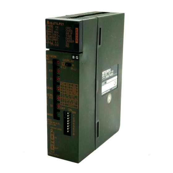
- Page 13 4. The Name and Setting of Each Part Indicates the name and setting of each part of Network Modules. A1SJ71LP21 A1SJ71LR21 A1SJ71LP21 A1SJ71LR21 OVER OVER S.MNG REM. AB. IF S.MNG REM. AB. IF DUAL SW.E. TIME DUAL SW.E. TIME D.LINK M/S.E.
- Page 14 Name Contents Name Status Contents Normal state The position A1SJ71LP21 of switch for WDT error, SP.UNIT ERROR A1SJ71LR21 the display Operating as control station or remote switch over master station (OFF: Normal station) A1SJ71LP21 of 6) is valid S.MNG Operating as sub-control station...
- Page 15 Name Contents Name Status Contents DATA Abnormal data larger than 2 kbytes are received. <Cause> Cable fault, noise, etc. UNDER Internal send data processing is not done at fixed intervals. <Cause> Hardware failure Dimly Data being sent Data being received Network number setting switch Network number setting (factory setting at time of shipping: 1) <Setting range>...
- Page 16 Name Contents Mode setting switch Mode setting (factory setting at time of shipping: 0) Mode Name Contents Online (automatic Data link with automatic online return online return effective) effective MODE Not used (Setting to this turns on the SW.E. LED.) Offline Disconnects the host station.
- Page 17 Name Contents 8) Connector Connect the optical fiber cable. (A1SJ71LP21) Hardware version G or later Front Reverse Forward Forward Reverse Optical fiber cable Hardware version F or earlier Front Forward Reverse Forward Reverse Optical fiber cable 9) Connector Connect the coaxial type cable.
- Page 18 5. Wiring DANGER Before wiring, be sure to shut off all phases of the external power supply used by the system. Failure to do so may cause electric shocks or damage the product. CAUTION Be sure there are no foreign substances such as sawdust or wiring debris inside the module.
- Page 19 5.1 Precautions for Laying Optical Fiber Cables (1) The optical fiber cable type that can be used differs depending on the station to station distance. Type Distance between stations SI optical fiber cable 500 m (1640.5 ft.) H-PCF optical fiber cable 1000 m (3281 ft.) Broad-band H-PCF optical fiber cable 1000 m (3281 ft.)
- Page 20 (5) Consider wiring using double-shielded coaxial cable in places that are subject to large amounts of noise. Double shielded coaxial cable Enlarged view of cable Sheath Sheath Mitsubishi Cable ... 5C-2V-CCY Internal conducter Insulation Grounding material External External conductor...
- Page 21 (6) Do not pull any of the connected cables. This will cause a faulty contact, cable disconnection, or damage to the module. (7) Please wire SD/RD of the connector for the cable correctly. Please do loopback test, the set confirmation test, and the bureau order confirmation test after wiring.
- Page 22 (7) Consider wiring using double-shielded coaxial cable in places that are subject to large amounts of noise. Double shielded coaxial cable Enlarged view of cable Sheath Sheath Mitsubishi Cable ... 5C-2V-CCY Internal conducter Insulation Grounding material External External conductor...
- Page 23 (12) There are integral type and separate F-type connectors. In the case of the separate F-type connector, tighten the ring of the connector until the ring is tight before connecting the connector to the network module. If the ring is loose, a communication error may occur. Turn clockwise (tightening direction) Integral F-type connector After connecting the F-type connector to the network module, retighten its...
- Page 24 5.2.3 Connecting the Connector for the Coaxial Cables The following section explains how to connect the BNC connector (connector plug for the coaxial cable) to the cable. (1) Structure of the BNC connector and coaxial cable The structure of the BNC connector and coaxial cable are shown in the figure below.
- Page 25 (d) Solder the contact to the internal conductor. Solder here (e) Insert the connector assembly in (d) into the plug shell and screw the nut into the plug shell. Important (1) Note the following precautions when soldering the internal conductor and contact.
-
Page 26: External Dimensions
OFF ON MODE MODE 0:ONLINE(A,R) 2:OFFLINE FRONT SIDE A1SJ71LP21 93.6 34.5 (0.26) (3.69) (1.36) Unit: mm (in.) *1: Please confirm details to Mitsubishi Electric System Service Corporation. 6.2 A1SJ71LR21 A1SJ71LR21 OVER S.MNG REM. AB. IF DUAL SW.E. TIME D.LINK M/S.E. - Page 27 6.3 A1SJ71BR11 A1SJ71BR11 OVER S.MNG REM. AB. IF SW.E. TIME D.LINK M/S.E. DATA T.PAS. PRM E. UNDER CPU R/W NETWORK DISPLAY X100 REM. N.ST Printed writing D.PRM GR.NO. ST,SIZE 8,16,32,64 board ST.NO. LB/LW SIZE 2,4,6,8k OFF ON MODE MODE 0 ONLINE (A,R) 2 OFFLINE At the time of installation of...
-
Page 28: Warranty
Warranty Mitsubishi will not be held liable for damage caused by factors found not to be the cause of Mitsubishi; machine damage or lost profits caused by faults in the Mitsubishi products; damage, secondary damage, accident compensation caused by special factors unpredictable by Mitsubishi;...
Need help?
Do you have a question about the A1SJ71LP21 and is the answer not in the manual?
Questions and answers