Table of Contents
Advertisement
Quick Links
Advertisement
Table of Contents
Troubleshooting

Related Manuals for Mitsubishi AJ65SBT2B-64AD


Summary of Contents for Mitsubishi AJ65SBT2B-64AD
-
Page 3: Safety Precautions
SAFETY PRECAUTIONS (Read these precautions before using this product.) Before using this product, please read this manual and the relevant manuals carefully and pay full attention to safety to handle the product correctly. The precautions given in this manual are concerned with this product only. For the safety precautions of the programmable controller system, refer to the user's manual for the CPU module used. - Page 4 [Installation Precautions] CAUTION ● Use the module in an environment that meets the general specifications in this manual. Failure to do so may result in electric shock, fire, malfunction, or damage to or deterioration of the product. ● For protection of the switches, do not remove the cushioning material before installation. ●...
- Page 5 [Wiring Precautions] CAUTION ● Prevent foreign matter such as dust or wire chips from entering the module. Such foreign matter can cause a fire, failure, or malfunction. ● Place the cables in a duct or clamp them. If not, dangling cable may swing or inadvertently be pulled, resulting in damage to the module or cables or malfunction due to poor contact.
- Page 6 [Startup and Maintenance Precautions] CAUTION ● Do not disassemble or modify the module. Doing so may cause failure, malfunction, injury, or a fire. ● Use any radio communication device such as a cellular phone or PHS (Personal Handy-phone System) more than 25cm away in all directions from the module. Failure to do so may cause malfunction.
-
Page 7: Conditions Of Use For The Product
PRODUCT in one or more of the Prohibited Applications, provided that the usage of the PRODUCT is limited only for the specific applications agreed to by Mitsubishi and provided further that no special quality assurance or fail-safe, redundant or other safety features which exceed the general specifications of the PRODUCTs are required. -
Page 8: Revisions
This manual confers no industrial property rights or any rights of any other kind, nor does it confer any patent licenses. Mitsubishi Electric Corporation cannot be held responsible for any problem involving industrial property rights which may occur as a result of using the contents noted in this manual. -
Page 9: Table Of Contents
INTRODUCTION Thank you for purchasing the Mitsubishi programmable controllers. Before using this product, please read this manual carefully and develop familiarity with the functions and performance of the programmable controller to handle the product correctly. CONTENTS SAFETY PRECAUTIONS ..........................A - 1 CONDITIONS OF USE FOR THE PRODUCT....................A - 5... - Page 10 CHAPTER 4 SETTINGS AND THE PROCEDURE BEFORE OPERATION 4 - 1 to 4 - 14 The Procedure Before Operation..................... 4 - 1 Handling Precautions........................4 - 2 Part Names ............................4 - 4 4.3.1 Transmission speed auto-tracking function ................4 - 7 Station Number Setting........................
-
Page 11: Manuals
COMPLIANCE WITH THE EMC AND LOW VOLTAGE DIRECTIVES (1) Method of ensuring compliance To ensure that Mitsubishi programmable controllers maintain EMC and Low Voltage Directives when incorporated into other machinery or equipment, certain measures may be necessary. Please refer to the "EMC AND LOW VOLTAGE DIRECTIVES"... -
Page 12: Generic Terms And Abbreviations
GENERIC TERMS AND ABBREVIATIONS Unless otherwise specified, the following generic terms and abbreviations are used in this manual to describe the AJ65SBT2B-64AD analog-digital converter module. Generic term/ Description abbreviation GX Developer The product name of the software package for the MELSEC programmable controllers... -
Page 13: Packing List
PACKING LIST The following items are included in the package of this product. Product Quantity AJ65SBT2B-64AD analog-digital converter module Analog-Digital Converter Module User's Manual (Hardware) Type AJ65SBT2B-64AD - 11... -
Page 14: Chapter 1 Overview
This user's manual explains the specifications, operations, and programming method of the AJ65SBT2B-64AD analog-digital converter module (hereafter abbreviated as AJ65SBT2B-64AD) used as a remote device station of a CC-Link system. The AJ65SBT2B-64AD changes analog values (voltage or current) to digital values (16-bit signed binary). Features This section describes the features of the AJ65SBT2B-64AD. - Page 15 OVERVIEW (8) Connection with up to 42 modules A master station can connect with up to 42 AJ65SBT2B-64ADs. (9) Easy maintenance The structure of the two-piece terminal block enables the user to remove a terminal block with wiring unchanged for easy maintenance. 1.1 Features...
-
Page 16: Chapter 2 System Configuration
SYSTEM CONFIGURATION CHAPTER 2 SYSTEM CONFIGURATION This chapter describes the system configuration when using the AJ65SBT2B-64AD. Overall Configuration The following Figure 2.1 shows an overall configuration when using the AJ65SBT2B- 64AD. CC-Link system master/local module (local station) CC-Link system master/local module (master station) -
Page 17: Applicable System
Refer to Section 5.6 for an example of the program using the dedicated instructions (RLPA and RRPA). Checking the Hardware Version The hardware version of the AJ65SBT2B-64AD can be checked in the DATE section on the rating plate. Date of manufacture... -
Page 18: Chapter 3 Specifications
* 1 Do not use or store the programmable controller under pressure higher than the atmospheric pressure of altitude 0m. Doing so may cause malfunction. When using the programmable controller under pressure, please consult your local Mitsubishi representative. * 2 This indicates the section of the power supply to which the equipment is assumed to be connected between the public electrical power distribution network and the machinery within premises. -
Page 19: Performance Specifications
SPECIFICATIONS Performance Specifications This section lists the performance specifications of the AJ65SBT2B-64AD. Table 3.2 Performance specifications Item AJ65SBT2B-64AD Voltage -10 to 10VDC (Input resistance: 1MΩ) Analog input Current 0 to 20mADC (Input resistance: 250Ω) Digital output 16-bit signed binary (-16384 to 16383) -
Page 20: I/O Conversion Characteristics
SPECIFICATIONS Table 3.2 Performance specifications Item AJ65SBT2B-64AD Applicable solderless •RAV1.25-3 (compliant with JIS C 2805) [Applicable wire size: 0.3 to 1.25mm terminal •V2-MS3, RAP2-3SL, TGV2-3N [Applicable wire size: 1.25 to 2.0mm M4 screw × 0.7mm × 16mm or more (tightening torque range: 0.78 to 1.08 N•m) -
Page 21: Voltage Input Characteristics
SPECIFICATIONS 3.3.1 Voltage input characteristics Figure 3.1 shows the graph of the voltage input characteristics. Analog input range for practical use 16383 16000 -384 -16000 -16384 Analog input value (V) Figure 3.1 Voltage input characteristics diagram Table 3.3 Voltage input characteristics table Analog input range Offset value Gain value... - Page 22 SPECIFICATIONS POINT (1) When values are within the analog input range and the digital output range, the resolution and accuracy are maintained within the range of performance specifications. If the values exceed these ranges, the resolution and the accuracy of performance specifications may not be maintained.
-
Page 23: Current Input Characteristics
SPECIFICATIONS 3.3.2 Current input characteristics Figure 3.2 shows the graph of the voltage input characteristics. Analog input range for practical use 16383 16000 -384 -16000 -16384 Analog input value (mA) Figure 3.2 Current conversion characteristics diagram Table 3.5 Current conversion characteristics table Analog input range Offset value Gain value... - Page 24 SPECIFICATIONS POINT (1) When values are within the analog input range and the digital output range, the resolution and accuracy are maintained within the range of performance specifications. If the values exceed these ranges, the resolution and the accuracy of performance specifications may not be maintained.
-
Page 25: Accuracy
3.3.4 Conversion speed The conversion speed of the AJ65SBT2B-64AD is 200µs/channel. The conversion speed is the time for taking in an analog input value and converting it to a digital output value. However, the CC-Link system requires additional time for data link processing. Therefore,... -
Page 26: Functions
SPECIFICATIONS Functions This section describes the functions of the AJ65SBT2B-64AD. 3.4.1 Function list This section lists the functions of the AJ65SBT2B-64AD. Table 3.7 Function list of the AJ65SBT2B-64AD Item Description Reference The A/D conversion can be enabled or disabled for each channel A/D conversion enable/disable using this function. -
Page 27: A/D Conversion Enable/Disable Function
SPECIFICATIONS 3.4.2 A/D conversion enable/disable function The A/D conversion can be enabled or disabled for each channel using this function. By setting A/D conversion disabled for unnecessary channels, the conversion cycle shortens. The conversion cycle is calculated with "Conversion speed (200µs) × Number of conversion-enabled channels". -
Page 28: Sampling Processing/Average Processing Specification
3.4.3 Sampling processing/average processing specification The conversion method can be specified from sampling processing/count average/time average/moving average for each channel in AJ65SBT2B-64AD. Specify the conversion method with the lower 8 bit in the CH Average processing setting (RWwm to RWwm+3). Then, in the specified conversion method, set the count average/ time average/moving average with the upper 8 bit. - Page 29 SPECIFICATIONS (1) Sampling processing A/D conversion is performed on analog input values sequentially at every cycle, and the digital output values are stored in a remote register. POINT The conversion cycle is calculated with "Conversion speed (200µs) × Number of conversion-enabled channels".
- Page 30 SPECIFICATIONS (3) Time average processing The A/D conversion is performed for the duration of the set time. The total of the converted values except a maximum value and a minimum value is averaged. Then, the average value is stored in the remote register. The number of conversion-enabled channels determines the processing times within the setting time.
- Page 31 SPECIFICATIONS (4) Moving average processing The module averages digital output values of the set number of times that are taken in for each sampling cycle. Then the module stores the averaged value in the remote register. The latest digital output value can be obtained since averaging processing is performed every sampling cycle.
-
Page 32: Input Range Setting Function
SPECIFICATIONS 3.4.4 Input range setting function The analog input range to be used in each channel can be set using this function. (1) Setting method Set an analog input range by combining ON/OFF of three remote output signals for each channel. (For CH1, set the range within CH1 Input range setting (0th bit) (RYn4) to CH1 Input range setting (2nd bit) (RYn6).) For the combinations of settings, refer to Table 3.9. -
Page 33: Remote I/O Signals
Remote output (RY) indicates the output signal from a master module to the AJ65SBT2B-64AD. The AJ65SBT2B-64AD uses 32 points of Remote input (RX) and 32 points of Remote output (RY) in communication with a master station. Table 3.10 List of remote I/O signals Signal direction: AJ65SBT2B-64AD →... -
Page 34: Details On Each Remote I/O Signal
SPECIFICATIONS 3.5.2 Details on each remote I/O signal This section describes the function of each remote I/O signal of the AJ65SBT2B-64AD. (1) CH A/D conversion completion flag (RXn0 to RXn3) A/D conversion completion flag (RXn0 to RXn3) in the corresponding channel turns on under the following sequential conditions: •... - Page 35 SPECIFICATIONS (7) Initial data processing request flag (RX(n+1)8) After power-on, this flag turns ON for the AJ65SBT2B-64AD to request an initial data. When Initial data processing completion flag (RY(n+1)8) is turned on, this flag turns off. Initial data processing request flag...
- Page 36 RX(n+1)A Error reset request flag RY(n+1)A : Executed by sequence program : Performed by the AJ65SBT2B-64AD Figure 3.6 Operation at error occurrence and reset (10)Remote ready (RX(n+1)B) After power-on, when the test mode ends or Initial data setting completion flag (RX(n+1)9) turns off after the initial data setting is completed, this flag turns ON.
- Page 37 SPECIFICATIONS (13)Initial data processing completion flag (RY(n+1)8) After power-on, or when requesting the initial data processing after the test mode operation, initial data processing is started. After completion of the processing, this flag is turned on. For the timing of turning on/off the remote I/O signal for the initial data setting, refer to Figure 3.5.
-
Page 38: Remote Register
SPECIFICATIONS Remote Register The AJ65SBT2B-64AD has a remote register for data communication with the master module. This section describes the assignment of the remote register. 3.6.1 List of remote register assignments Table 3.11 shows the remote register assignments. Table 3.11 Remote register assignments... -
Page 39: Chapter 4 Settings And The Procedure Before Operation
OPERATION CHAPTER 4 SETTINGS AND THE PROCEDURE BEFORE OPERATION The Procedure Before Operation This section describes the procedure before operation of the AJ65SBT2B-64AD. Start Station number switch setting Refer to Section 4.3, Section 4.4. (Set the station number of the AJ65SBT2B- 64AD.) -
Page 40: Handling Precautions
SETTINGS AND THE PROCEDURE BEFORE OPERATION Handling Precautions This section describes precautions for handling the AJ65SBT2B-64AD. WARNING ● Do not touch any terminal while power is on. Doing so will cause electric shock or malfunction. CAUTION ● Prevent foreign matter such as dust or wire chips from entering the module. - Page 41 TH35-7.5Fe TH35-7.5Al (b) Installation screw intervals Tighten the screws at intervals of 200mm or less. (3) When mounting the AJ65SBT2B-64AD to a DIN rail, push in the DIN rail hook until it clicks. DIN rail DIN rail hook Figure 4.2 Mounting a module to a DIN rail (4) For names, specifications, and manufacturers of applicable cables, refer to the user's manual for the master module used.
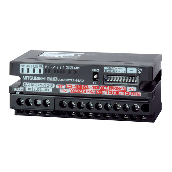
- Page 42 SETTINGS AND THE PROCEDURE BEFORE OPERATION Part Names This section describes the part names of the AJ65SBT2B-64AD. TEST +24V TEST Figure 4.3 Appearance of the AJ65SBT2B-64AD 4.3 Part Names...
-
Page 43: 4.3 Part Names
SETTINGS AND THE PROCEDURE BEFORE OPERATION Table 4.2 Part names Name Description On: Power supply on PW LED Off: Power supply off Normal operation Flashing: 0.1s intervals: Any of the following occurs: An analog value outside the analog input range is input. A user range read error occurs. - Page 44 A hook to mount the module to a DIN rail This switch is turned on to enable the built-in terminating resistor. L TER. (Line This switch is used when the AJ65SBT2B-64AD is connected at the network termination. Termination) switch Its factory default setting is off.
-
Page 45: Transmission Speed Auto-Tracking Function
SETTINGS AND THE PROCEDURE BEFORE OPERATION 4.3.1 Transmission speed auto-tracking function The transmission speed is automatically set depending on the master module setting; therefore, it does not need to be set on the AJ65SBT2B-64AD side. 4.3 Part Names 4.3.1 Transmission speed auto-tracking function... -
Page 46: Station Number Setting
SETTINGS AND THE PROCEDURE BEFORE OPERATION Station Number Setting The station number setting of the AJ65SBT2B-64AD determines the buffer memory addresses of the master module in which remote I/O signals and read/write data are to be stored. For details, refer to the user's manual for the master module used. -
Page 47: Wiring Of Data Link Cables
64AD. When replacing the AJ65SBT-64AD with the AJ65SBT2B-64AD, rewire the system using a communication terminal block for the AJ65SBT2B-64AD. 4.6.2 Connecting modules using CC-Link dedicated cables Figure 4.5 shows how to connect the AJ65SBT2B-64AD to a master module and an I/O module using CC-Link dedicated cables. Master module AJ65SBT2B-64AD I/O module, etc. -
Page 48: Wiring With External Devices
This section explains wiring precautions and wiring with external devices of the AJ65SBT2B-64AD. 4.7.1 Wiring precautions To obtain the maximum performance from the functions of the AJ65SBT2B-64AD and improve the system reliability, an external wiring with high durability against noise is required. Precautions for external wiring are as follows: (a) Use separate cables for the AC control circuit and the external input signals of the AJ65SBT2B-64AD to avoid the influence of the AC side surges or induction. - Page 49 Figure 4.6 Wiring with external devices * 1 Use shielded twisted pair cables. * 2 Input resistors of the AJ65SBT2B-64AD * 3 For the current input, wire between the V+ and I+ terminals. * 4 If there is noise or ripples in the external wiring, connect a 0.1 to 0.47µF capacitor (25V or higher voltage-resistant product) between the V+ and COM terminals.
-
Page 50: Offset/Gain Setting
When correcting errors of digital output values in the user range setting 1 and 2, follow the procedure described in Figure 4.7. On the AJ65SBT2B-64AD, the offset/gain setting can be configured without communication with the master station. In such case, follow the procedure described in Figure 4.8. - Page 51 SETTINGS AND THE PROCEDURE BEFORE OPERATION (2) Configuring the offset/gain setting without communication with the master station Start Apply a voltage or pass a current generating an offset value for one second or more. For voltage For current Short the TEST terminals to enter test mode. Switch the SELECT/SET switch to the SET position.
-
Page 52: Maintenance And Inspection
LED. Maintenance and Inspection The AJ65SBT2B-64AD has no special item to be inspected. However, to maintain the best condition of the system, perform the inspection in accordance with the items described in the user's manual of the CPU module used. -
Page 53: Chapter 5 Programming
For the master module, refer to the user's manual for the master module used. Programming Procedure Create a program to perform the A/D conversion in the AJ65SBT2B-64AD, according to the procedure in Figure 5.1. Start Configure A/D conversion enable/disable setting. -
Page 54: Conditions Of Program Examples
RWr1 CH2 Digital output value RWr2 RWr2 CH3 Digital output value D1102 D1103 RWr3 RWr3 CH4 Digital output value Figure 5.3 Update overview of the CPU module, master module, and AJ65SBT2B-64AD (For the QCPU (Q mode), LCPU, QnACPU) 5.2 Conditions of Program Examples... - Page 55 RWr3 RWr3 CH4 Digital output value D303 Figure 5.4 Update overview of the CPU module, master module, and AJ65SBT2B-64AD (For the ACPU/QCPU (A mode)) In a program example with the RRPA instruction (auto refresh parameter setting) for the ACPU/ QCPU (A mode) (refer to Section 5.6), RWr0 to RWr3 are assigned to D456 to D459.
-
Page 56: Program Example When Using The Qcpu (Q Mode)
PROGRAMMING Program Example When Using the QCPU (Q mode) Set parameters in "Network Parameter" of GX Works2. (1) Parameter settings (a) Network parameter setting Figure 5.5 "CC-Link Module Configuration" dialog box (when using the QCPU (Q mode)) Table 5.1 "CC-Link Module Configuration" dialog box setting (when using the QCPU (Q mode)) Setting item Setting value Number of Modules... - Page 57 PROGRAMMING (b) Station information setting Figure 5.6 "Station Information Module 1" dialog box (when using the QCPU (Q mode)) Table 5.2 "Station Information Module 1" dialog box setting (when using the QCPU (Q mode)) Setting item Setting value Station Type Remote Device Station Exclusive Count Exclusive Station 1...
- Page 58 Y1000 to Signal for various settings of the AJ65SBT2B-64AD Y101A Signal where the data link status of the AJ65SBT2B-64AD is stored 0 (OFF): Data link is normal 1 (ON): Data link is error Reset command pulse signal for Error flag...
- Page 59 PROGRAMMING (3) Program example Checking the connection status of the AJ65SBT2B-64AD Reads the data link status Turns on MC contact (M100) when the data link is normal Turns on Y60 when a data link error occurs Initial setting CH1 A/D conversion enable/disable...
- Page 60 PROGRAMMING Turns on Y63 when an error occurs Error reset request flag (RY1A): ON Resetting Error reset request flag Error reset request flag (RY1A): OFF Figure 5.8 Program example (when using the QCPU (Q mode)) 2/2 5.3 Program Example When Using the QCPU (Q mode)
-
Page 61: Program Example When Using The Lcpu
PROGRAMMING Program Example When Using the LCPU The program example when using the QCPU can also be used for the LCPU. Set parameters according to the description in this section and use the program example in Section 5.3 (3). Set parameters in "Network Parameter" of GX Works2. (1) Parameter settings (a) PLC parameter Change the I/O assignment setting of the built-in I/O function according to the... - Page 62 PROGRAMMING (b) Network parameter setting Figure 5.10 "CC-Link Module Configuration" dialog box (when using the LCPU) Table 5.4 "CC-Link Module Configuration" dialog box setting (when using the LCPU) Setting item Setting value Number of Modules 1 (Boards) Start I/O No. 0000 Type Master Station...
- Page 63 PROGRAMMING (c) Station information setting Figure 5.11 "Station Information Module 1" dialog box (when using the LCPU) Table 5.5 "Station Information Module 1" dialog box setting (when using the LCPU) Setting item Setting value Station Type Remote Device Station Exclusive Count Exclusive Station 1 Reserve/Invalid Station Select No Setting...
-
Page 64: Program Example When Using The Qnacpu
PROGRAMMING Program Example When Using the QnACPU Set parameters in "Network parameters" of GX Developer. (1) Parameter settings (a) Network parameter setting Figure 5.12 "Setting the CC Link List" dialog box (when using the QnACPU) Table 5.7 "Setting the CC Link List" dialog box setting (when using the QnACPU) Setting item Setting value No. - Page 65 PROGRAMMING (b) Station information setting Figure 5.13 "station Information. Module 1" dialog box (when using the QnACPU) Table 5.8 "station Information. Module 1" dialog box setting (when using the QnACPU) Setting item Setting value Station type Remote device station Exclusive station count Exclusive station 1 Reserve/invalid station select No setting...
- Page 66 Y1000 to Signal for various settings of the AJ65SBT2B-64AD Y101A Signal where the data link status of the AJ65SBT2B-64AD is stored 0 (OFF): Data link is normal 1 (ON): Data link is error Reset command pulse signal for Error flag...
- Page 67 PROGRAMMING (3) Program example Checking the connection status of the AJ65SBT2B-64AD Reads the data link status Turns on MC contact (M100) when the data link is normal Turns on Y60 when a data link error occurs Initial setting CH1 A/D conversion enable/disable...
- Page 68 PROGRAMMING Turns on Y63 when an error occurs Error reset request flag (RY1A): ON Resetting Error reset request flag Error reset request flag (RY1A): OFF Figure 5.15 Program example (when using the QnACPU) 2/2 - 16 5.5 Program Example When Using the QnACPU...
-
Page 69: Program Example When Using The Acpu/Qcpu (A Mode) (Dedicated Instructions)
Signal which is output when an error occurs Y100 to Signal for various settings of the AJ65SBT2B-64AD Y11A Signal where the data link status of the AJ65SBT2B-64AD is stored 0 (OFF): Data link is normal 1 (ON): Data link is error Network parameter setting start pulse signal... - Page 70 (2) Program example Setting the network parameter using the RLPA instruction Synchronous mode: Disable Number of connected modules: 1 Station information of the AJ65SBT2B-64AD (remote device station, occupying 1 station, station No.1) Dedicated instruction (RLPA) Start I/O number of the master...
- Page 71 Sets 256 points Dedicated instruction (RRPA) Start I/O number of the master module Start device for storing parameter Checking the connection status of the AJ65SBT2B-64AD Reads the data link status Turns on MC contact (M100) when the data link is normal...
- Page 72 PROGRAMMING CH2 Average processing setting (RWw1): Count average (16 times) Initial data processing completion flag (RY18): ON Initial data setting request flag (RY19) : ON Changing the initial setting CH1 A/D conversion enable/disable setting (RY00): A/D conversion disable CH2 A/D conversion enable/disable setting (RY01): A/D conversion disable Initial data setting request flag (RY19) : ON...
-
Page 73: Program Example When Using The Acpu/Qcpu (A Mode) (From/To Instructions)
Signal which is output when an error occurs Y100 to Signal for various settings of the AJ65SBT2B-64AD Y11A Signal where the data link status of the AJ65SBT2B-64AD is stored 0 (OFF): Data link is normal 1 (ON): Data link is error Network parameter setting start pulse signal... - Page 74 Remote input signal Reads devices RX00 to RX1F to devices X100 to X11F Checking the connection status of the AJ65SBT2B-64AD Reads the data link status Turns on MC contact (M100) when the data link is normal Turns on Y60 when a data link error occurs Figure 5.19 Program example (when using the ACPU/QCPU (A mode) (FROM/TO instructions)) 1/3...
- Page 75 PROGRAMMING Initial setting CH1 A/D conversion enable/disable setting (RY00): A/D conversion enable CH2 A/D conversion enable/disable setting (RY01): A/D conversion enable CH1 Input range setting (RY04 to RYn6): 0 (-10 to 10V) CH2 Input range setting (RY07 to RY09): 1 (0 to 5V) CH1 Average processing setting (RWw0) : Moving average (16 times) CH2 Average processing setting (RWw1)
- Page 76 PROGRAMMING Turns on Y63 when an error occurs Error reset request flag (RY1A): ON Resetting Error reset request flag Error reset request flag (RY1A): OFF Writing remote output signals Figure 5.21 Program example (when using the ACPU/QCPU (A mode) (FROM/TO instructions)) 3/3 - 24 5.7 Program Example When Using the ACPU/QCPU (A mode) (FROM/TO Instructions)
-
Page 77: Chapter 6 Troubleshooting
Error Check Method by the LED Display This section describes how to check errors by the LED display of the AJ65SBT2B-64AD. For errors related to the CPU module and the master module, refer to the user's manual for the modules. - Page 78 This flag turns on if the write to the flash memory is failed when configuring the offset/gain setting. In this case, turn the power supply of the AJ65SBT2B-64AD from off 0.1s Is Flash memory write error flag to on.
- Page 79 TROUBLESHOOTING (5) When the L ERR. LED flashes regularly Table 6.4 When the L ERR. LED of the AJ65SBT2B-64AD flashes regularly Check item Action Turn off the power supply of the AJ65SBT2B-64AD, Is the station number setting switch changed during...
-
Page 80: When The Digital Output Value Cannot Be Read
TROUBLESHOOTING When the Digital Output Value Cannot Be Read Table 6.7 When the digital output value cannot be read Check item Action Check the CPU module or the master module. Does an error occur in a CPU module or the master When an error occurs, refer to the user's manual of module? the CPU module or the master module used and... -
Page 81: Troubleshooting When The Err. Led Of The Master Station Flashes
TROUBLESHOOTING Troubleshooting When the ERR. LED of the Master Station Flashes The "ERR." LED of the master station is flashing. Are the parameter setting and the system configuration consistent? Correct the parameter setting or the system configuration. Are the link special registers of the master station, SW0080 to SW0083 (Other station data link... - Page 82 * 1 For the failure of the master module or corresponding modules, please consult your local Mitsubishi representative. * 2 Check for a short circuit, reversed connection, disconnection, terminating resistor, FG connection, overall cable distance, and station-to-station distance.
-
Page 83: When Hardware Error Flag (Rxna) Turns On
TROUBLESHOOTING When Hardware Error Flag (RXnA) Turns on In this case, turn the power supply of the AJ65SBT2B-64AD from off to on. If Hardware error flag (RXnA) turns on even after turning the power supply from off to on, the possible cause is a failure of the AJ65SBT2B-64AD. -
Page 84: Appendix
APPENDIX APPENDIX Appendix 1 External Dimensions The following figures show the external dimensions of the AJ65SBT2B-64AD. 109.5 Mounting hole (2-4.5 5.1, M4 screw) DIN rail center Unit: mm... - Page 85 APPENDIX Memo...
- Page 86 INDEX Initial data setting request flag (RY(n+1)9) ••••••••3-20 Input range setting function•••••••••••••••••••••• 3-9,3-15 Absolute maximum input ••••••••••••••••••••••••••••••• 3-2 Intelligent device station•••••••••••••••••••••••••••••• A-10 Accuracy ••••••••••••••••••••••••••••••••••••••••••••• 3-2,3-8 I/O conversion characteristics••••••••••••••••••••••••• 3-3 ACPU •••••••••••••••••••••••••••••••••••••••••••••••••••• A-10 A/D conversion enable/disable function••••••• 3-9,3-10 L ERR. LED••••••••••••••••••••••••••••••••••••••••••••••• 4-5 L RUN LED •••••••••••••••••••••••••••••••••••••••••••••••...
- Page 87 Resolution••••••••••••••••••••••••••••••••••••••••••••••••• 3-2 RLPA••••••••••••••••••••••••••••••••••••••••••••••••••••••• 2-2 RRPA •••••••••••••••••••••••••••••••••••••••••••••••••••••• 2-2 RUN LED•••••••••••••••••••••••••••••••••••••••••••••••••• 4-5 RWr •••••••••••••••••••••••••••••••••••••••••••••••••••••••A-10 RWw ••••••••••••••••••••••••••••••••••••••••••••••••••••••A-10 RX •••••••••••••••••••••••••••••••••••••••••••••••••••••••••A-10 RY •••••••••••••••••••••••••••••••••••••••••••••••••••••••••A-10 Sampling processing/average processing specification ••••••••••••••••••••••••••••••••••••••••••••• 3-11 SB •••••••••••••••••••••••••••••••••••••••••••••••••••••••••A-10 SELECT/SET switch •••••••••••••••••••••••••••••••••••• 4-5 Station number setting ••••••••••••••••••••••••••••••••• 4-8 Station number setting switch••••••••••••••••••••••••• 4-6 SW ••••••••••••••••••••••••••••••••••••••••••••••••••••••••A-10 Terminal block for analog input signal•••••••••••••••...
- Page 88 6. Failure caused by reasons unpredictable by scientific technology standards at time of shipment from Mitsubishi. 7. Any other failure found not to be the responsibility of Mitsubishi or that admitted not to be so by the user. 2. Onerous repair term after discontinuation of production (1) Mitsubishi shall accept onerous product repairs for seven (7) years after production of the product is discontinued.
- Page 90 Applicant: MITSUBISHI ELECTRIC AUTOMATION KOREA CO,LTD Equipment Name: PLC Country of Origin: JAPAN Date of Manufacture: Otherwise noted Manufacturer: MITSUBISHI ELECTRIC CORPORATION 사용자 안내문 이 기기는 업무용(A급) 전자파적합기기로서 A급기기 판매자 또는 사용자는 이 점을 주의하시기 바라며, 가정외의 지역에서 사용하는 것을...
Need help?
Do you have a question about the AJ65SBT2B-64AD and is the answer not in the manual?
Questions and answers