Icom IC-2820H Instruction Manual
Dual band fm transceiver
Hide thumbs
Also See for IC-2820H:
- Instruction manual (164 pages) ,
- Service manual (56 pages) ,
- Basic operations (4 pages)
Table of Contents
Advertisement
Quick Links
INSTRUCTION MANUAL
DUAL BAND FM TRANSCEIVER
i2820H
This device complies with Part 15 of the FCC rules. Operation is sub-
ject to the following two conditions: (1) This device may not cause
harmful interference, and (2) this device must accept any interference
received, including interference that may cause undesired operation.
Advertisement
Table of Contents

Related Manuals for Icom IC-2820H


Summary of Contents for Icom IC-2820H
- Page 1 INSTRUCTION MANUAL DUAL BAND FM TRANSCEIVER i2820H This device complies with Part 15 of the FCC rules. Operation is sub- ject to the following two conditions: (1) This device may not cause harmful interference, and (2) this device must accept any interference received, including interference that may cause undesired operation.
- Page 2 IC-2820H. We want to take a couple of moments of your time to thank you for making your IC-2820H your radio of choice, and hope you agree with Icom’s philosophy of “technology first.” Many EXPLICIT DEFINITIONS hours of research and development went into the design of your IC-2820H.
- Page 3 Changes or modifications to this device, not ex- cle may be hindered or where it could cause bodily injury. pressly approved by Icom Inc., could void your authority to operate this device under FCC regulations.
-
Page 4: Table Of Contents
SUPPLIED ACCESSORIES TABLE OF CONTENTS FOREWORD ................... i IMPORTANT .................... i EXPLICIT DEFINITIONS ................. i PRECAUTIONS ..................ii SUPPLIED ACCESSORIES ..............iii TABLE OF CONTENTS ................. iii QUICK REFERENCE GUIDE ............I–XII I Installation ..................I I Your first contact ................. VIII I Repeater operation ................ - Page 5 I Selecting output power ..............20 9 DTMF MEMORY ENCODER ............. 48–51 I One-touch PTT function ............... 21 I Programming a DTMF code ............48 I Audio mute function ..............21 I Transmitting a DTMF code ............50 I DTMF speed ................51 4 REPEATER OPERATION ............
-
Page 6: Quick Reference Guide
QUICK REFERENCE GUIDE I Installation D Precaution— magnets D Installation methods RCAUTION • Single body installation Magnets are used for the controller’s attachment to the main unit. Transceiver NEVER hold the whole unit by the controller only when carry- ing the transceiver. Carry the transceiver holding the main unit. - Page 7 QUICK REFERENCE GUIDE D Location Select a location which can support the weight of the trans- • Remote installation ceiver and does not interfere with driving. We recommend the Front panel locations shown in the diagram below. NEVER place the transceiver or remote controller where nor- mal operation of the vehicle may be hindered or where it could cause bodily injury.
- Page 8 (3.4 m; 11.2 ft) for re- when using self-tapping screws. are supplied with the IC-2820H. mote installation, wInsert the supplied screws, nuts and washers through the Connect the controller and the main unit using with the sup- mounting bracket and tighten.
- Page 9 QUICK REFERENCE GUIDE D Microphone connection D Controller’s attachment A microphone connector is available on the main unit front You can attach the controller of the IC-2820H in one of 2 panel. Connect the supplied microphone connector as illus- methods. trated below.
- Page 10 • CONNECTING TO A DC POWER SOURCE to the bracket Grommet Remote controller bracket IC-2820H Hint! The supplied remote controller bracket may fits to a mount- ing angle, such as for car TV set as below. Ask your car ac- −...
- Page 11 Use a 13.8 V DC power supply with at least 15 A capacity. Make sure the ground terminal of the DC power supply is grounded. • CONNECTING TO A DC POWER SUPPLY IC-2820H DC power supply 13.8 V to an −...
- Page 12 QUICK REFERENCE GUIDE D Antenna installation • Antenna connector • Antenna location The antenna uses a PL-259 connector. To obtain maximum performance from the transceiver, select a high-quality antenna and mount it in a good location. It is • PL-259 CONNECTOR not necessary to use radials on a magnetic mount (“mag q Slide the coupling ring 30 mm...
-
Page 13: I Your First Contact
2. Selecting the main band The IC-2820H displays 2 frequencies on left and right bands Now that you have your IC-2820H installed in your car or simultaneously. However, transmission, some keys and mi- shack, you are probably excited to get on the air. We would crophone’s operation are accepted for the main band only. - Page 14 3. Selecting the operating frequency band 4. Tune the frequency The IC-2820H has 2 m and 70 cm bands for each left and The tuning dial will allow you to dial in the frequency you want right band. The operating band can be exchanged between to operate.
-
Page 15: I Repeater Operation
QUICK REFERENCE GUIDE I Repeater operation 1. Setting duplex Using the HM-133 Plus or minus duplex selection and the repeater tone setting Push desired band’s [MAIN•BAND] to select the main band. can be made easily via HM-133. Push [DUP•MONI] once or twice to select minus duplex or Push [ 7(TONE)] for minus duplex;... -
Page 16: I Programming Memory Channels
QUICK REFERENCE GUIDE I Programming memory channels The IC-2820H has a total of 522 memory channels 3. Writing a memory channel (including for storing often used operat- 20 scan edges and 2 call channels) Push and hold the same band’s [M/CALL•MW] for 1 sec. to ing frequency, repeater settings, etc. - Page 17 QUICK REFERENCE GUIDE Using the HM-133 q Push [MR/CALL] to select memory mode. wPush [ C(T-OFF)] first, then enter the desired memory channel via the keypad. ePush [VFO/LOCK] to select VFO mode, then set the de- sired operating frequency, including offset direction, tone settings, etc.
-
Page 18: Panel Description
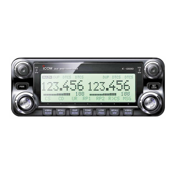
PANEL DESCRIPTION I Front panel— controller Function display (pgs. 3, 4) i2820H DUAL BAND TRANSCEIVER V/MHz M/CALL TONE M/CALL V/MHz *The keys w to t are for SCAN MONI DTMF PRIO SCAN the MAIN band only. q POWER KEY [PWR] r TONE•DTMF KEY [TONE•DTMF] ➥... - Page 19 PANEL DESCRIPTION Left band Right band i2820H DUAL BAND TRANSCEIVER V/MHz M/CALL TONE M/CALL V/MHz SCAN MONI DTMF PRIO SCAN *The same controls for both the left and right bands are arranged in symmetry. y SQUELCH CONTROL [SQL] !0 VFO/MHz TUNING•SCAN KEY [V/MHz•SCAN] ➥...
-
Page 20: I Function Display
PANEL DESCRIPTION I Function display *The same indications for both the left and right bands are arranged. q OPERATING MODE INDICATOR (p. ??) r TONE INDICATOR ➥ During FM mode operation: Shows the selected operating mode. G “TONE” appears while the repeater tone is in use. •... - Page 21 PANEL DESCRIPTION ➥ During DV* (Digital) mode operation: !1 DTMF INDICATOR G “DSQL” appears while the digital call sign squelch Appears while DTMF memory function is in use.(p. ??) function is in use. !2 FREQUENCY READOUT G “CSQL” appears while the digital code squelch func- Shows the operating frequency, set mode contents, etc.
- Page 22 PANEL DESCRIPTION I Function display— continued *The same indications for both the left and right bands are arranged. !9 OUTPUT POWER INDICATORS @2 MAIN INDICATOR (p. ??) “LOW” appears when low output power; “MID” appears Indicates the main band for transmit and function control. when middle output power, “HI”...
- Page 23 PANEL DESCRIPTION Function guide indications (pgs. ??–??) @3 FREQUENCY MARKER (p. ??) Shows the selected frequency in the band scope. @4 CENTER FREQUENCY MARKER Shows the center frequency of the band scope. @5 BAND SCOPE INDICATOR When the band scope function is in use, shows the band conditions.
- Page 24 PANEL DESCRIPTION I Function guide indications tMEMORY NAME INDICATION KEY [M.N](LOW•PRIO) The function guide indications allow you to simplifying a wide variety of function operation (p. ??) Push select the memory name indication condition. D Function guide • Memory name, frequency and OFF selections are available. y SINGLE WATCH KEY [SNGL](M/CALL•MW) (p.
- Page 25 PANEL DESCRIPTION !1 CALL SIGN SET KEY [R>CS](TONE•DTMF) (p. ??) !7 G PS MEMORY RECALL KEY [GMR](TONE•DTMF) Push to copy and set the previously received station call (p. ??) sign as the station call sign for the call. Push to select the GPS memory screen to display the stored positon information.
-
Page 26: I Main Unit
PANEL DESCRIPTION I Main unit rPACKET JACKS [PACKET] (p. V) Connect a TNC , etc. for data com- (Terminal Node Controller) munications. The receiver can support 9600 bps packet communication (AFSK) t MICROPHONE CONNECTOR [MIC] Connects the supplied or an optional microphone. q +8 V DC output (Max. - Page 27 PANEL DESCRIPTION u COOLING FAN • Speaker information Rotates while transmitting. Connected Left band audio Right band audio Also rotates while receiving depending on the setting in speaker set mode. (p. ??) No external Internal speaker (mixed audio) speakers i ANTENNA CONNECTOR [ANT2] [SP-1] only External speaker (mixed audio) Connects a 50 Ω...
-
Page 28: I Microphone (Hm-133)
PANEL DESCRIPTION I Microphone (HM-133*) ➥ Push and hold either key for 1 sec. to start scanning. (p. 41) r ACTIVITY INDICATOR ➥ Lights red while any key, except [FUNC] and [DTMF-S], is pushed, or while transmitting. ➥ Lights green while the one-touch PTT function is in use. t KEYPAD (pgs. -
Page 29: I Microphone Keypad
PANEL DESCRIPTION I Microphone keypad FUNCTION SECONDARY FUNCTION ( +key) OTHER FUNCTIONS Switches between opening and closing the In VFO mode enters operating band select- squelch. (p. 16) ing condition. (p. 12) In memory mode enters bank selecting condition. (p. 35) Starts and stops scanning. - Page 30 PANEL DESCRIPTION FUNCTION SECONDARY FUNCTION ( +key) OTHER FUNCTIONS ➥ Cancels frequency entry. ➥ Selects a memory channel for program- (p. 13) ➥ Cancels the scan or priority watch. ming. (p. 31) ➥ Advances the memory channel number (pgs. 41, 47) ➥...
- Page 31 PANEL DESCRIPTION I Optional Microphone (HM-154) *A different microphone may be supplied de- pending on version. q PTT SWITCH Push and hold to transmit; release to receive. w UP/DOWN KEYS [UP]/[DN] ➥ Push either key to change operating frequency, mem- ory channel, set mode setting, etc.
- Page 32 OFF. D MAIN band [DIAL] The IC-2820H can receive 144 MHz and 430(440) MHz band signals simultaneously. To activate all functions access or to change frequency via the microphone, you must designate one band as the main band. The transceiver transmits a sig- Frequency band initial is displayed.
-
Page 33: Setting A Frequency
✔ About extra frequency bands [M/CALL•MW] — USA and General versions only In addition to the 2 m and 70 cm ham bands, the IC-2820H USA and General versions have extra frequency bands for each left and right bands as follow. -
Page 34: I Using The Tuning Dial
SETTING A FREQUENCY I Using the tuning dial I Using the keypad The frequency can be directly set via numeral keys on the mi- q Rotate the desired band’s [DIAL] to set the frequency. crophone. • If VFO mode is not selected, push the same band’s [V/MHz•SCAN] to select VFO mode. -
Page 35: I Tuning Step Selection
SETTING A FREQUENCY I Tuning step selection ePush [TS](M/CALL•MW) (Left band’s) to enter tuning step Tuning steps are the minimum frequency change increments when you rotate [DIAL] or push [Y]/[Z] on the microphone. set mode. Independent tuning step for the left and right, as well as each frequency bands can be set for individual tuning convenience. -
Page 36: I Lock Functions
SETTING A FREQUENCY I Lock functions D Microphone keypad lock To prevent accidental frequency changes and unnecessary function access, use the lock function. The transceiver has 2 This function locks the microphone keypad. different lock functions. ➥ Push [FUNC] then [ D(16KEY-L)] to turn D Frequency lock 16KEY-L... -
Page 37: Basic Operation
The main band’s audio and squelch level can also IMPORTANT! (for 50 W transmission): SQLY/Z Y(TONE-1)]/[ Z 0(TONE-2)] be adjusted with [ The IC-2820H is equipped with protection circuit to protect and [ D(MUTE)]/[ #(16KEY-L)], respectively. the power amplifier circuit from high SWR (Standing Wave •... -
Page 38: I Selecting Output Power
BASIC OPERATION I Selecting output power I Operating mode selection The transceiver has 3 output power levels to suit your oper- Operating modes are determined by the modulation of the ating requirements. Low output powers during short-distance radio signals. The transceiver has total 5 operating modes communications may reduce the possibility of interference to . - Page 39 BASIC OPERATION I Squelch attenuator D Squelch attenuator setting The transceiver has an RF attenuator related to the squelch q Push [F• level setting. Approx. 10 dB attenuation is obtained at maxi- ] to display the function guide. wPush [MENU](V/MHz•SCAN) mum setting.
- Page 40 BASIC OPERATION I V/V, U/U simultaneous receive (Para-watch) The IC-2820H can simultaneously receive two signals on the To activate the para-watch function from the HM-133, enter same band, such as 144 MHz band, using the para-watch the desired frequencies for each the left and right bands using function.
- Page 41 BASIC OPERATION I Sub band mute/busy beep I Monitor function The sub band mute function automatically cuts out sub band This function is used to listen to weak signals without disturb- audio signals when both main and sub band signals are re- ing the squelch setting.
- Page 42 D D Diversity operation Dualwatch operation monitors two frequencies simultane- The diversity receiving compares the receiving signal strength ously. The IC-2820H has two independent receiver circuits: from two different antennas, ANT1 and ANT2, and automati- left band, and right band cally selects the strongest signal.
-
Page 43: I One-Touch Ptt Function
BASIC OPERATION I One-touch PTT function The PTT switch can be operated as a one-touch PTT switch (each push toggles between transmit/receive). Using this When the diversity operation is in use, connect the same function you can transmit without pushing and holding the grade antenna, connected to [ANT1], shuld be connected PTT switch. -
Page 44: I Audio Mute Function
BASIC OPERATION I Audio mute function I Band scope This function temporarily mutes the audio without disturbing The band scope function allows you to visually check a spec- the volume setting. (microphone only) ified frequency range around the center frequency. ➥... - Page 45 BASIC OPERATION D D Single sweep D D Monitoring a signal q Set the desired frequency as band scope center frequency. If you find a signal that you want to monitor during/after w Push [F• ] to display the function guide. sweep, you can monitor the signal with the following opera- ePush [SCP](DUP•MONI) to start a single sweep.
-
Page 46: Repeater Operation
Set the subaudible tone (repeater tone) encoder function ON. - Set the subaudible tone frequency, if required. • The IC-2820H USA version has the auto repeater function. Thus the steps 3 and 4 may not be necessary, depending on the setting. -
Page 47: I Accessing A Repeater
REPEATER OPERATION I Accessing a repeater qSet the receive frequency (repeater output frequency) on r Push and hold [PTT] to transmit. the main band. (pgs. ??–??) • The displayed frequency automatically changes to the transmit wPush [DUP•MONI] one or two times, to select minus du- frequency (repeater input frequency). - Page 48 REPEATER OPERATION z Set the receive frequency (repeater output fre- m Push [ 9(TSQL)] to return to simplex opera- SIMP DUP– SIMP quency) on the main band. (pgs. 11–13) tion. x Push [ • “DUP” or “DUP–” indicator disappears. – 7(TONE)] to select minus duplex; , To turn OFF the subaudible tone encoder, push push [ + 8(TSQLS)] to select plus duplex.
-
Page 49: I Subaudible Tones
REPEATER OPERATION I Subaudible tones (Encoder function) D Subaudible tones z Set the main band, mode/channel you wish to qSelect the main band, mode/channel you wish to set the set the subaudible tones to, such as VFO mode or memory/call channel. subaudible tones to, such as VFO mode or memory/call •... - Page 50 REPEATER OPERATION D DTMF tones D 1750 Hz tone ➥ Push [DTMF-S], then push the keys of the de- The microphone has 1750 Hz tone capability, used for ring DTMF-S sired DTMF digits. tone when calling, etc. • The function indicator lights green. z Push [FUNC].
-
Page 51: I Offset Frequency
REPEATER OPERATION I Offset frequency z Push [BAND] to select the desired band When communicating through a repeater, the transmit fre- (left or quency is shifted from the receive frequency by an amount as the main band. right) • Enter the desired frequency via the keypad if neces- determined by the offset frequency. -
Page 52: I Auto Repeater (Usa Version Only)
REPEATER OPERATION I Auto repeater U.S.A./KOREAN versions only q Push [F• The U.S.A. and Korean versions automatically use standard ] to display the function guide. wPush [MENU](V/MHz•SCAN) repeater settings (duplex ON/OFF, duplex direction, tone encoder to enter MENU (Right band’s) when the operating frequency falls within or outside ON/OFF) screen. - Page 53 REPEATER OPERATION...
-
Page 54: Memory Operation
MEMORY OPERATION I General description D Using the [Y]/[Z] keys The transceiver has 522 memory channels including 20 scan edge memory channels , and 2 call channels. Each (10 pairs) z Push [BAND] to select the desired band as of these channels can be individually programmed with oper- MR/CALL the main band. -
Page 55: I Programming A Memory Channel
MEMORY OPERATION I Programming a memory channel eRotate the [DIAL] to select the memory channel to be pro- VFO settings, including MENU group’s contents such as sub- audible tone frequency, offset, can be programmed into a grammed. memory channel. • Memory channels not yet programmed are blank. rPush and hold the same band’s [M/CALL•MW] for 1 sec. - Page 56 MEMORY OPERATION D Programming a memory channel via the microphone The microphone can also be used to program mem- ory channels. z Set the desired frequency in VFO mode. v Push [VFO/LOCK] to select VFO mode. ➥ Push [VFO/LOCK] to select VFO mode. b Push [FUNC] then push and hold [ A(MW)] for 1 sec.
- Page 57 MEMORY OPERATION I Memory bank selection z Push [MR/CALL] to select memory mode, if de- The IC-2820H has a total of 26 banks . All memory (A to Z) BANK sired. channels, regular, scan edges and call channels are assigned...
-
Page 58: I Memory Bank Setting
MEMORY OPERATION I Memory bank setting qPush the desired band’s [M/CALL•MW] several times to uPush [BACK](V/MHz•SCAN) to set the bank (Right band’s) select memory mode, then rotate the same band’s [DIAL] initial and channel number. • “X” indicator blinks. to select the desired memory channel. iPush and hold [S.MW](M/CALL•MW) wPush and hold the same band’s [M/CALL•MW] for 1 sec. - Page 59 MEMORY OPERATION I Programming memory/bank/scan name Each memory channel can be programmed with an alphanu- • Push [12](M/CALL•MW) to turn the character group (Right band’s) meric channel name for easy recognition and can be indi- from numbers or symbols. cated independently by channel. Names can be a maximum •...
- Page 60 MEMORY OPERATION [EXAMPLE]: Programming the bank name “AIR” into the scan edge channel 3A. Memory mode M/CALL V/MHz Push (Main band's) to select memory mode. Push (Main band's) several times SCAN to select “B NAME”. EDIT M/CALL Push (Right band's) to enter bank name edit mode.
- Page 61 MEMORY OPERATION I Transferring memory contents This function transfers a memory channel’s contents to VFO . This is useful when searching (or another memory/call channel) for signals around a memory channel frequency and for re- calling the offset frequency, subaudible tone frequency etc. z Push [BAND] to select the desired band as MR/CALL the main band, if necessary.
- Page 62 MEMORY OPERATION D Memory/call➪call/memory q Select the memory/call channel to be transferred. ➥ Push the desired band’s [M/CALL•MW] several times to select memory mode or call channel, then rotate the same band’s [DIAL] to select the desired memory or call channel. w Push and hold the same band’s [M/CALL•MW] for 1 sec.
- Page 63 MEMORY OPERATION I Memory clearing Contents of programmed memories can be cleared (blanked), if desired. qPush [V/MHz•SCAN] to select VFO mode in the desired tPush [BACK](V/MHz•SCAN) to return to VFO (Right band’s) band mode. (left or right) wPush and hold the same band’s [M/CALL•MW] for 1sec. NOTE: Be careful!—...
- Page 64 MEMORY OPERATION I Erasing/transferring bank contents rRotate [DIAL] to select the desired bank initial Contents of programmed memory banks can be cleared or (A to Z) transferred to another bank. transfer. • Select no indication, “– – – –,” when erasing the contents from INFORMATION: Even if the memory bank contents are the bank.
-
Page 65: Call Channel Operation
CALL CHANNEL OPERATION I Call channel selection I Call channel transferring D Call➪VFO/Memory Call channel is pre-programmed memory channel that can be accessed by simply pushing call channel button. q Push the desired band’s [M/CALL•MW] several times to select cal channel mode, then rotate the same band’s ➥... -
Page 66: I Programming A Call Channel
CALL CHANNEL OPERATION I Programming a call channel r Push the [M/CALL•MW] for 1 sec. to program. Operating frequency, duplex information, subaudible tone in- • 3 beeps sound and the unit returns to VFO mode automatically. formation (tone encoder or tone squelch ON/OFF and its fre- quency) can be programmed into the call channel. -
Page 67: Scan Operation
SCAN OPERATION I Scan types Scanning searches for signals automatically and makes it There are 7 scan types and 4 resume conditions to suit your easier to locate new stations for contact or listening purposes. operating needs. Repeatedly scans all frequen- Repeatedly scans all frequen- FULL SCAN SELECTED BAND SCAN... -
Page 68: I Scan Start/Stop
SCAN OPERATION I Scan start/stop D Preparation z Push [VFO/LOCK] to select VFO mode for Scan resume condition (p. ??); program the scan edges SCAN full/programmed scan; push [MR/CALL] to select (pgs. ??, ??); program 2 or more memory channels (pgs. ??, memory mode for memory scan, in the main ??);... -
Page 69: I Scan Edges Programming
SCAN OPERATION I Scan edges programming r Push the [M/CALL•MW] for 1 sec. to program. Scan edges can be programmed in the same manner as • 3 beeps sound and VFO is automatically selected. memory channels. Scan edges are programmed into scan •... - Page 70 SCAN OPERATION D Programming scan edges via microphone z Set the desired frequency in VFO mode. b To program a frequency for the other scan edge channels, ➥ Push [VFO/LOCK] to select VFO mode. repeat steps z to v. ➥ Set the frequency via the keypad or [Y]/[Z]. x Push [FUNC] then [ A(MW)] momentarily.
-
Page 71: I Skip Channel Setting
SCAN OPERATION I Skip channel setting z Select a memory channel. The memory skip function speeds up scanning by checking ➥ Select memory mode by pushing [MR/CALL]. only those memory channels not set as skip channels. Set ➥ Push [Y] or [Z] to select the desired channel skip channels as follows. -
Page 72: I Scan Resume Condition
SCAN OPERATION I Scan resume condition z Push [BAND] to select the desired band (left or The scan resume condition can be selected as timer or pause scan. The selected resume condition is also used for right) as the main band. x Push [ priority watch. -
Page 73: I Priority Watch Types
PRIORITY WATCH I Priority watch types Priority watch checks for signals on a VFO frequency every MEMORY CHANNEL WATCH 5 sec. while operating in memory mode. The transceiver has While operating on a VFO fre- 5 sec. 3 priority watch types to suit your needs. You can also trans- quency, priority watch checks for 50 msec. -
Page 74: I Priority Watch Operation
PRIORITY WATCH I Priority watch operation q Select VFO mode; then, set an operating frequency in the z Select VFO mode; then, set the desired fre- PRIO desired MAIN band (left or right). quency. w Set the watching channel(s). x Set the watching channel(s). For memory channel watch: For memory channel watch: Select the desired memory channel. -
Page 75: Dtmf Memory Encoder
DTMF MEMORY ENCODER I Programming a DTMF code r Rotate the [DIAL] to select the DTMF memory “ ” t Push [MAIN•BAND] to enter the DTMF memory program- DTMF tones are used for autopatching, controlling other ming condition. equipment, etc. The transceiver has 16 DTMF memory chan- •... - Page 76 DTMF MEMORY ENCODER D Programming a DTMF code— via microphone b Push [VFO/LOCK] to exit the programming condition. z Push [FUNC] then [ 6(DTMF)] to turn the DTMF • The [ A(MW)] key cannot be used to exit. If pushed, code “A” DTMF encoder ON.
-
Page 77: I Transmitting A Dtmf Code
DTMF MEMORY ENCODER I Transmitting a DTMF code D Automatic transmission (DTMF memory) D Transmitting a DTMF memory directly qPush and hold [TONE•DTMF] for 1 sec. to turn the z Push [FUNC] then [ 6(DTMF)] to turn the “AUTO DTMF-S DTMF memory encoder ON. -
Page 78: I Dtmf Speed
DTMF MEMORY ENCODER I DTMF speed D Manual transmission z Deactivate the DTMF memory encoder by The rate at which DTMF memories send individual DTMF DTMF-S pushing [FUNC] then [ B(D-OFF)]. characters can be set to accommodate operating needs. x Push [DTMF-S] to turn the DTMF direct selec- q Push [F F •... - Page 79 TONE SQUELCH AND POCKET BEEP I Tone frequency and DTCS code D Subaudible (repeater) tone Some repeaters require subaudible tones to be accessed. Subaudible tones are superimposed over your normal signal and must be set in advance. (P ??) D Tone, DTCS, Digital code and Digital call sign squelches The tone squelch (CTCSS), DTCS squelch, digital code squelch or digital call sign squelch opens only when receiving...
- Page 80 DTMF MEMORY ENCODER D Setting tone squelch D Setting DTCS code for DTCS squelch or beep q Push [F F • ] to display the function guide. w Push [V/MHz•SCAN] (Right band’s) to enter MENU q Push [F F • ] to display the function guide.
- Page 81 DTMF MEMORY ENCODER I Digital code and digital call sign setting The optional UT-123 D Setting digital code for digital code squelch D Setting the YOUR and MY call signs for or beep digital call sign squelch or beep q Push [F F • ] to display the function guide, push the left See page ?? for DV MODE OPERATION.
- Page 82 DTMF MEMORY ENCODER I Tone/DTCS squelch operation z Set the operating frequency. The tone or DTCS squelch opens only when receiving a sig- TSQL x Program the CTCSS tone frequency or DTCS nal with the same pre-programmed subaudible tone or DTCS code, respectively.
-
Page 83: I Pocket Beep Operation
DTMF MEMORY ENCODER I Digital code/digital call sign I Pocket beep operation squelch q Set the desired operating frequency and the desired oper- The optional UT-123 ating mode. q Set the desired operating frequency on DV mode, Digital w Set the desired CTCSS tone, DTCS code, Digital call sign code and MY CALL SIGN. - Page 84 DTMF MEMORY ENCODER I DTCS polarity setting z Set the operating frequency. TSQLS x Program the CTCSS tone frequency or DTCS q Push [F F • ] to display the function guide. code in set mode. ➥ Push [ w Push [V/MHz•SCAN] (Right band’s) to enter MENU B(D-OFF)] to enter set mode.
-
Page 85: I Tone Scan
DTMF MEMORY ENCODER I Tone scan r When the CTCSS tone frequency or 3-digit DTCS code is By monitoring a signal that is being operated with pocket beep, tone or DTCS squelch function, you can determine the matched, the squelch opens and the tone frequency is tone frequency or DTCS code necessary to open a squ elch. - Page 86 PAGER/CODE SQUELCH I Pager function I Code programming D D Before programming This function uses DTMF codes for paging and can be used as a “message pager” to confirm you of a caller’s identification The pager and code squelch functions require ID codes and a even when you leave the transceiver temporarily unattended.
- Page 87 PAGER/CODE SQUELCH D D Code programming y Rotate [DIAL] to select a transmit code channel from C1 to Your ID code MUST be programmed into code channel C0. C5, then push the [MAIN•BAND]. Up to 6 transmit codes (codes that you transmit) are pro- u Enter the desired 3-digit transmit code via the keypad.
- Page 88 PAGER/CODE SQUELCH I Pager operation D Calling a specific station u After confirming a connection, push [MAIN•BAND] to enter the “PGR/C-SQL” set mode, then rotate [DIAL] to select q Program the pager code channel in advance (p. 39). the code squelch operation “C-SQL,” or non-selective w Set the operating frequency.
- Page 89 PAGER/CODE SQUELCH I Code squelch • PERSONAL CALLS This display appears when you are called with your ID code and the calling station’s ID code is 123. When using code squelch you will only receive calls from sta- tions which know your ID or group code. A 3-digit code is sent each time [PTT] is pushed in order to open the receiving sta- “CP”...
- Page 90 “ ” indicator appear • u Set the operating frequency of the controller transceiver equal to the sub band frequency of the IC-2820H. • Make sure a tone frequency is set when using the optional tone squelch function with the IC-2820H.
- Page 91 EXTERNAL DTMF REMOTE [EXAMPLE] 144.750 MHz [ENT] 1 MHz mode CALL Memory channel 15 HIGH [ENT] mode 2 digits LOW1 Scratch pad memory 2 DOWN Call [DOWN] [DOWN] channel Note for the [ENT] key • When the entered frequency is outside of the frequency coverage, the DTMF KEYPAD input digits will be cleared.
- Page 92 DIGITAL MODE OPERATION (Optional UT-123 is required ) D D Your own call sign programming Although [DIAL] and [ï](5) are used for description in this section, [∫ ∫ ](2)/[√ √ ](8) and [≈ ≈ ](6) are available instead of Your own call sign must be programmed for both digital voice [DIAL] and [ï](5).
- Page 93 DV MODE OPERATION (Optional UT-123 is required) y Push [≈ ≈ ](6) to select 2nd digit, then rotate [DIAL] !0 Push [ï](5) to store the programmed call sign with note † to se- lect the desired character or code. and returns to MY CALL SIGN screen. !1 Push [MENU/LOCK] to return to frequency indication.
- Page 94 DV MODE OPERATION (Optional UT-123 is required) D D Station call sign programming y Push [≈ ≈ ](6) to select 2nd digit, then rotate [DIAL] † to se- Station call sign must be programmed for the specified sta- lect the desired character or code. tion call as well as repeater operation in both digital voice and •...
- Page 95 DV MODE OPERATION (Optional UT-123 is required) NOTE: During the call sign programming mode (r to u), push [CQ](0) to set “CQCQCQ,” and push [CQ](0) again to return to the previously stored call sign. ✔ For your information The IC-91A/91AD has call sign edit record function. When editing a call sign stored in a call sign memory, regular memory or call channel, the default setting is to store the edited call sign into a blank channel automatically.
- Page 96 DV MODE OPERATION (Optional UT-123 is required) I Digital voice mode operation qSet the desired frequency in B band. NOTE: The digital mode operation is vastly different from (pgs. 14, 18) • Select output power, if desired. (p. 24) FM mode. One of the differences is in digital mode the w Select DV mode.
- Page 97 DV MODE OPERATION (Optional UT-123 is required) D D When calling the desired station D D When sending a CQ Continued instruction from step x on page 38. Continued instruction from step x on page 38. cRotate [DIAL] † † cRotate [DIAL] †...
- Page 98 DV MODE OPERATION (Optional UT-123 is required) I About D-STAR system For current repeater operation, stations that are communicat- ing must both be in the same repeater’s operating area. In the D-STAR system, repeater linking via a 10 GHz band However, in the D-STAR system as in the illustration at left, backbone and internet network (gateway connection) capa- the repeaters can be linked via the system repeaters (with a...
- Page 99 DV MODE OPERATION (Optional UT-123 is required) I Digital repeater operation u Repeat the steps t and y to enter the desired repeater Repeater call signs must be programmed for repeater opera- tion in both digital voice and low-speed data communications. call sign.
- Page 100 DV MODE OPERATION (Optional UT-123 is required) D D Repeater operation in the same zone t Push [PTT] to transmit; release to receive. qSet the desired repeater’s frequency, offset and shift direc- tion in B band. (pgs. 18, 31) • Select DV mode in advance. (p. 21) w Set your own call sign.
- Page 101 DV MODE OPERATION (Optional UT-123 is required) • Setting example 1 Zone Area 1 Repeater 1 Area 2 Repeater 2 Area 3 Repeater 3 Area 4 Repeater 4 : A11111 : A22222 (Gateway) : A33333 : A44444 Station A Station C Station B : A2222A : A4444C...
- Page 102 DV MODE OPERATION (Optional UT-123 is required) D D Repeater operation into another zone nPush [ï](5) to set the call sign for “R2.” qSet the desired repeater’s frequency, offset and shift direc- • Return to CALL SIGN screen. tion in B band. (pgs.
- Page 103 DV MODE OPERATION (Optional UT-123 is required) • Setting example 2 Zone A Repeater 3 Repeater 3 3 Repeater 3 Area 1 Area 2 Area 4 : A33333 : A33333 : A33333 Area 3 (Gateway) Repeater 1 Repeater 2 Repeater 4 : A11111 : A22222 : A44444...
- Page 104 DV MODE OPERATION (Optional UT-123 is required) I Received call sign • Station call sign • Called station call sign RX CALL SIGN RX CALL SIGN RX01 RX01 RX01 RX01 When a call is received in DV mode, the calling station and CALLER: CALLER: CALLED:...
- Page 105 DV MODE OPERATION (Optional UT-123 is required) D D One-touch reply using the call record The stored call signs in the call record can be used to the call. Important! Setting call signs with the “One-touch reply using the call qAfter receiving a call, push and hold [RX➝CS](CALL) for record”...
- Page 106 DV MODE OPERATION (Optional UT-123 is required) I Copying the call sign • When “AUTO” is set to “EDIT RECORD” item D D Copying the call sign memory contents r Push [≈ ≈ ](6) to select the call sign programming mode. This function is convenient when or modifying a part of the •...
- Page 107 DV MODE OPERATION (Optional UT-123 is required) • When “SELECT” is set to “EDIT RECORD” item r Push [≈ ≈ ](6) to select the call sign programming mode. • The 1st digit of the selected call sign blinks. tEdit or modify the selected call sign as described in “D Sta- tion call sign programming”...
- Page 108 DV MODE OPERATION (Optional UT-123 is required) D D Copying the call record contents into call • When “CALLER,” “RXRPT1” or “RXRPT2” is selected sign memory zPush [≈ ≈ ](6) then rotate [DIAL] † to select the desired con- This is a way to copying the call record contents (“CALLER,”...
- Page 109 DV MODE OPERATION (Optional UT-123 is required) I Break-in communication • How to use the break-in? While operating with the call sign squelch , the (p. 110) The break-in function allows you to break into a conversation, squelch never opens even if a call is re- (no audio sounds) where the two original stations are communicating with call...
- Page 110 DV MODE OPERATION (Optional UT-123 is required) I Message operation D D TX message programming r Rotate [DIAL] † TX messages are available for up to 5 channels and each to select the desired character or symbol. • Push [A/a](3) to change the character group from “AB” (alpha- channel can be programmed with a message of up to 20 betical characters;...
- Page 111 DV MODE OPERATION (Optional UT-123 is required) D D Message Transmission ✔ For your information Select the message transmission function ON (Ch01–05) OFF. When a message channel is selected, the transceiver The automatic received call sign and/or message indication transmits a text message (default: OFF) can be turned OFF in display set mode, if desired.
- Page 112 DV MODE OPERATION (Optional UT-123 is required) I Automatic reply function D D RX message indication The automatic reply function replies to calls by a station that specified your call sign. The received message can also be checked in DV set mode. Two methods of replying are available—...
- Page 113 DV MODE OPERATION (Optional UT-123 is required) D D Voice memory recording for automatic reply D D Play-back or erase the voice memory q Push [MENU/LOCK] to select menu mode indication. IMPORTANT! wRotate [DIAL] † to select “DV VOICE MEMO,” then push Deactivate the dualwatch function and set minimum [VOL] †...
- Page 114 DV MODE OPERATION (Optional UT-123 is required) I EMR communication I Low-speed data communication The EMR communication mode is available for digital mode In addition to the digital voice communication, low-speed data operation. In the EMR communication mode, no call sign set- communication is available.
- Page 115 DV MODE OPERATION (Optional UT-123 is required) D D Low-speed data communication application D D Transmission condition setting setting q Enter “DV DATA TX” in DV set mode. (p. 92) ➪ ➪ MENU screen DV SET MODE DV DATA TX Configure the low-speed data communication application as †...
- Page 116 DV MODE OPERATION (Optional UT-123 is required) I GPS operation D D Sentence formatter setting During GPS mode operation, a GPS receiver (RS-232C out- can be connected to the [DATA] socket of put/NMEA format) q Enter “GPS MODE” in DV set mode. (p.
- Page 117 DV MODE OPERATION (Optional UT-123 is required) D D GPS message programming t Repeat the steps r and t to enter the desired message. q Enter “GPS” in message/position set mode. • Up to 20-character messages can be set. ➪ ➪...
- Page 118 DV MODE OPERATION (Optional UT-123 is required) D D GPS message automatic transmission D D Position indication q Enter “GPS AUTO TX” in DV set mode. q Enter “POSITION” in message/position set mode. (p. 95) ➪ ➪ ➪ ➪ MENU screen DV SET MODE...
- Page 119 DV MODE OPERATION (Optional UT-123 is required) D D Received GPS message indication q Enter “RX GPS” in message/position set mode. ➪ ➪ MENU screen MESSAGE/POSITION RX GPS † † (Push [MENU/LOCK]) (Rotate [DIAL] , then push [ï](5) • RX GPS MESSAGE screen is displayed. RX GPS MESSAGE RX GPS MESSAGE DATA:...
- Page 120 DV MODE OPERATION (Optional UT-123 is required) I Other functions for DV mode operation D D DV voice memory N Track size setting The IC-91A/91AD has a DV voice memory that records a total The track size can be changed with the following instruction. 30 second of received audio.
- Page 121 DV MODE OPERATION (Optional UT-123 is required) D D DV automatic detect N Playing-back and erasing the recorded audio The “DV” mode indicator blinks when a non-DV signal is re- qSelect DV mode in B band, and deactivate the priority ceived during DV mode operation.
- Page 122 OTHER FUNCTIONS I General MENU screen is used for programming infrequently changed z Push [BAND] to select the main band. values or conditions of functions. x Push [ B(D-OFF)] to enter set mode. c Push [ • Entering MENU screen and operation B(D-OFF)] or [ C(T-OFF)] to select q Push [F F •...
- Page 123 OTHER FUNCTIONS I Items list D D CALL SIGN † D D SET MODE ITEMS REF. ITEMS REF. ITEMS REF. ITEMS REF. p. 92 p. 94 TIME-OUT TIMER SQL DELAY — — YOUR CALL SIGN MY CALL SIGN p. 92 p.
-
Page 124: Other Functions
OTHER FUNCTIONS D D DUP/TONE D D DV GPS ITEMS REF. ITEMS REF. ITEMS REF. ITEMS REF. p. 92 p. 94 p. 92 p. 94 GPS SENTENCE GPS TX OFFSET FREQ WX ALERT p. 92 p. 94 p. 92 p. 94 GPS MESSAGE GPS AUTO TX REPEATER TONE... - Page 125 OTHER FUNCTIONS...
-
Page 126: I Set Mode
OTHER FUNCTIONS I SET MODE items D D Busy lockout Turns the busy lockout function ON and OFF(default.) D D Time-out timer This function inhibits transmission while receiving a signal or To prevent accidental prolonged transmission, etc., the trans- when the squelch is open ceiver has a time-out timer. - Page 127 Selects squelch delay from short and long to prevent re- The following items are selectable by optional UT-123 is in- peated opening and closing of the squelch during reception stalled into the IC-2820H. of the same signal. • Short : Short squelch delay. (default) D D Auto reply •...
- Page 128 OTHER FUNCTIONS D D Digital monitor D D Repeater call sign auto write Sets the desired monitoring mode during DV MODE OPERA- When accessing a repeater with a call sign different than is TION (Optional UT-123 is required) from “Auto,” “Digital” and programmed, the repeater call sign can be set into “RPT1”...
- Page 129 OTHER FUNCTIONS D D EMR comunication D D Bank link scan Turns the EMR comunication mode ON and OFF. (default) Sets the memory bank link function ON and OFF. The (default) link function provides continuous bank scan, scanning all con- D D Break-in comunication tents in the selected banks during bank scan.
- Page 130 OTHER FUNCTIONS I DUP/ TONE items D D DTCS code Sets DTCS code (both encoder and decoder) for DTCS D D Offset frequency squelch operation. Total of 104 codes are available. (default: 023) Sets the duplex offset frequency within 0 to 159.995 MHz range.
- Page 131 (Low contrast) (High contrast) (default: 8) D D Opening logo The opening logo indication (Icom logo and transceiver name) that is displayed at power ON can be skipped, if desired. • ON : Opening logo is displayed at power ON. (default)
- Page 132 OTHER FUNCTIONS D D RX message Display Available only when the UT-123 is installed. D D Opening call sign Sets auto received message display function AUTO and OFF. Available only when the UT-123 is installed. When this setting is set to AUTO, the transceiver automati- The set your own call sign, programmed in my call sign, can cally indicates and scrolls the received message.
- Page 133 OTHER FUNCTIONS I SOUND items D D Standby Beep Available only when the UT-123 is installed. D D Key-touch beep Turns the beep emission capability ON and OFF when the com- The key-touch beep can be turned OFF for silent operation. municating station finishes transmitting or the receive signal dis- (default: ON) appears while in the DV MODE OPERATION (Optional UT-123...
- Page 134 OTHER FUNCTIONS I DV GPS items D D GPS message See P?? to the chapter 13 for detils. D D GPS sentence D D RX GPS message q Enter the MENU screen in the function guide. w Rotate the main band’s [DIAL] to select “DV GPS,” then Selects the data transmission speed for packet operation push the main band’s [MAIN•BAND] to enter the sentence from 1200 bps (default) and 9600 bps.
- Page 135 OTHER FUNCTIONS I PACKET items D D UTC OFFSET D D Packet BPS Selects the UTC offset -12:00 to +12:00. Turn every 5 min- Selects the data transmission speed for packet operation utes. (default: 0:00) from 1200 bps (default) and 9600 bps. D D GPS DATUM D D Packet operation band Selects the GPS datum 0 (default) to 224.
-
Page 136: I Weather Channel Operation (Usa Version Only)
OTHER FUNCTIONS I Weather channel operation U.S.A. version only q Select the desired weather channel. D D Weather channel selection w Turn the weather alert function ON in set mode. [M/CALL•MW] ➥ Push [F F • ] to enter set mode. ➥... -
Page 137: I Microphone Keys
OTHER FUNCTIONS I Microphone keys D D [F-1]/[F-2] keys on HM-133 The following conditions in the main band or both left and The supplied HM-133’s (optional for some versions) [F-1] and right bands can be memorized into [F-1] and [F-2] keys, in- [F-2] keys memorize the transceiver conditions. -
Page 138: I Partial Reset
OTHER FUNCTIONS I ALL reset I Partial reset POWER ON POWER ON The function display may occasionally display erroneous in- If you want to initialize the operating conditions (VFO fre- formation (e.g. when first applying power). This may be quency, VFO settings, menu group’s contents) without clear- caused externally by static electricity or by other factors. -
Page 139: I Data Cloning
OTHER FUNCTIONS I Data cloning POWER ON w While pushing left band’s [M/CALL•MW], turn power ON Cloning allows you to quickly and easily transfer the pro- grammed contents from one transceiver to another; or , data to enter cloning mode (master transceiver only— power on from a personal computer to a transceiver using the optional only for sub-transceiver). -
Page 140: I Packet Operation
OTHER FUNCTIONS I Packet operation D Cloning using a personal computer Data can be cloned to and from a personal computer (Mi- D Data speed crosoft Windows 98/2000/Me/XP) using the optional CS- ® ® For packet operation, the transceiver can be set to one of two 2820 and the optional cloning cable CLONING SOFTWARE... - Page 141 OTHER FUNCTIONS q Connect the transceiver and a TNC as illustrated below. D DATA JACK PIN ASSIGNMENT TNC side q DATA IN TX AUDIO w GND e PTT P Front panel view y P SQL q DATA IN Input terminal for data transmit. See p. ?? for details on RX AUDIO t AF OUT how to toggle data speed between 1200...
- Page 142 OTHER FUNCTIONS D 9600 bps high speed packet operation • Read the instructions supplied with your TNC carefully The transceiver supports 2 modes of 9600 bps packet opera- before attempting packet operation with the transceiver. tion: G3RUH and GMSK. • Pin t AF OUT is for 1200 bps operation only. This pin q Connect the transceiver and a TNC as illustrated below.
- Page 143 OTHER FUNCTIONS D Adjusting the transmit signal output from • When using the PTT P terminal for packet operation, no the TNC voice signals are transmitted from the microphone. When setting data transmission speed to 9600 bps, the data • When pushing [PTT] during data transmission, data signal coming from the TNC is applied exclusively to the in- transmission is interrupted and the voice signal takes pri- ternal limiter circuitry to automatically maintain band width.
-
Page 144: Maintenance
MAINTENANCE I Troubleshooting If your transceiver seems to be malfunctioning, please check the following points before sending it to a service center. PROBLEM POSSIBLE CAUSE SOLUTION REF. Does not turn on. • Power connector has a poor contact. • Check the connector pins. —... -
Page 145: I Fuse Replacement
MAINTENANCE PROBLEM POSSIBLE CAUSE SOLUTION REF. Some memory channels • The memory channel number has not yet been • Select the channel via the microphone keypad to — cannot be selected via the programmed. check whether the channel has been programmed tuning dial. -
Page 146: Specifications And Options
SPECIFICATIONS AND OPTIONS I Specifications D D GENERAL D D TRANSMITTER • Frequency coverage (unit: MHz) • Modulation system : Variable reactance frequency modulation • Output power : 50/15/5 W* (approx.) Version Left Band Right Band *25/15/5 W only for the Taiwan version. Rx: 118–173.995* , 375–549.995,* USA,... -
Page 147: I Options
SPECIFICATIONS AND OPTIONS Same as that supplied with the transceiver. 3.5 m (11.5 ft) OPC-1529R DATA COMMUNICATION CABLE • Sensitivity (for RX bands; for your reference only) Allows you to slow-speed data communication in DV mode and data Frequency range Left band (µV) Right band (µV) cloning operation. -
Page 148: Mode Arrangement
MODE ARRANGEMENT... - Page 149 MODE ARRANGEMENT...
- Page 150 A-6124D-1EX Printed in Japan 1-1-32 Kamiminami, Hirano-ku, Osaka 547-0003, Japan 2006 Icom Inc. ©...
Need help?
Do you have a question about the IC-2820H and is the answer not in the manual?
Questions and answers