Icom IC-2820H Basic Operations
Hide thumbs
Also See for IC-2820H:
- Instruction manual (164 pages) ,
- Service manual (56 pages) ,
- Instruction manual (150 pages)
Table of Contents
Advertisement
Quick Links
These instructions are not a substitute for reading the manual
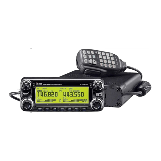
IC-2820 Front Panel: 1) Power, 2) Function/Lock key 3) Output Power/Priority, 4) Tone/DTMF, 5) Duplex/Monitor, (Button 2-5 are for
the MAIN band only), 6) SQL, 7) VOL, 8) DIAL, 9) MAIN band (push), 10) VFO/Tune/Scan, 11) Memory/Call/Memory write.
IC-2820 LCD Panel: Of note: 1) Operating mode indicator, 2) Duplex indica-
tors, 3) Name indicator if programmed, 4) Tone indicator, 5/6) Not relevant
without D-Star board, 10) Lock function enabled, 17) Weather indicators if
programmed, 19) Power level, 22) MAIN band indicator
The IC-2820 has a magnetic attached face plate. The connector cable may not be attached to the radio initially (use the short one, not
the long extender cable). Note that the six-pin end goes into the main unit and the four-pin end goes into the face plate. The micro-
phone should already be attached and covered by a faceplate.
NOTE: The IC-2820 is a dual receive radio with a left and right side and set of keys and
knobs. The active side is identified by a MAIN icon in the top "left" corner of the ac-
tive display. When the instructions refer to MAIN key or knob, they refer to the active
transceiver side and do not affect the inactive side until the inactive side is made active.
To select the MAIN band, either press the DIAL knob on the side you wish to set ac-
tive.
Icom IC-2820H Basic Operations
IC-2820 Main body: 1) Controller connector (6-
pin), 2) & 3) Not used, 4) Packet data jack, 5)
Mic, 6) Antenna (primary), 8) Antenna
(optional), 9) External speaker, 10) External
speaker—see External speakers.
Prince William County ARES
IC-2820 Quick Reference Guide v.1.4
Advertisement
Table of Contents

Subscribe to Our Youtube Channel
Related Manuals for Icom IC-2820H


Summary of Contents for Icom IC-2820H
- Page 1 Icom IC-2820H Basic Operations These instructions are not a substitute for reading the manual IC-2820 Front Panel: 1) Power, 2) Function/Lock key 3) Output Power/Priority, 4) Tone/DTMF, 5) Duplex/Monitor, (Button 2-5 are for the MAIN band only), 6) SQL, 7) VOL, 8) DIAL, 9) MAIN band (push), 10) VFO/Tune/Scan, 11) Memory/Call/Memory write.
- Page 2 Preprogrammed Memory Channels and Frequencies IC-2820 Memory Memory Name/Purpose Frequency Tone Channel OVH2M/Operations and Logistics 146.970 - 100 Hz WWI2M/Operations and Logistics 147.240 + NVFM2M/Fairfax ARES 146.790 - NVREGN/Northern Virginia Regional Operations and 146.910 - Coordination SKYWARN/National Weather Service—Sterling 147.300 + MDREGN/Maryland Regional Operation and Coordination 147.105 + MTVERN/Mount Vernon (Alexandria)
- Page 3 Power Turning the power on and off (Pg. 15) [PWR] To turn the radio on, press and hold the button For 1 second (Fig. 1). The LCD will show the current power supply voltage for 2 seconds before switching to normal mode. [PWR] To turn the radio off, press and hold the button...
- Page 4 MONI button to change between off, DUP-, and DUP+ This works ONLY for the active frequency. Cross Band Enabling the cross band function (Icom KB 743G461664) Repeater Configure the band(s) as needed with power levels and TONE as needed. Operations Press and hold both left and right MAIN dials then the FUNCTION key to- gether.
Need help?
Do you have a question about the IC-2820H and is the answer not in the manual?
Questions and answers