Omron ZX Series Manual
Displacement sensor and parallel beam sensor
Hide thumbs
Also See for ZX Series:
- Operation manual (188 pages) ,
- Manual (26 pages) ,
- Manual (28 pages)
Table of Contents
Advertisement
Quick Links
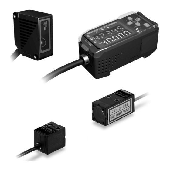
Displacement Sensor and Parallel Beam Sensor
Compact Amplifier With Digital
Resolution Display Supports 3 Through-
Beam and 8 Displacement Visible Red
Sensing Heads
■
Amplifier supports displacement and parallel
beam sensing applications
■
Diffuse distance measurement up to 500 mm
■
Through-beam measurement up to 10 mm
■
Selectable linear analog output 4-20 mA,
1 to 5 VDC, 0 to 5 VDC,
■
Amplifier displays achieved resolution of
application
■
3 discrimination outputs: High, Low, Pass
■
FDA class 1 and class 2 visible red laser
■
PC interface for setup, monitoring, direct data
logging
Ordering Information
Important note for ordering:
Choose normally stocked products whenever possible to ensure availability that matches your schedule. Normally stocked items are
shown as shaded in the Ordering Information tables. Non-stocked items are available but are subject to longer lead times. For the most
up-to-date information on stock status, contact your Omron representitive.
Sensor Heads
■
Reflective
Optical system
Beam shape
Diffuse reflective
Spot beam
Line beam
Regular reflective
Spot beam
Line beam
Note:
For an average sampling of 4,096.
Through-beam
Optical system
Measuring width
Through-beam
1-mm dia.
5 mm
10 mm
Note:
1. For an average sampling of 64.
2. Availability pending
±
±
4 VDC,
5 VDC
Beam size at sensing
Sensing distance ±
distance
measurement range
40 µm x 30 µm
40±10 mm (1.57 in ±0.40 in)
100 µm x 65 µm
100±40 mm (3.93 in ±1.57 in)
180 µm x 300 µm
300±200 mm (11.81 in ±7.87 in) 300 µm
2000 µm x 50 µm
40±10 mm (1.57 in ±0.40 in)
2000 µm x 100 µm
100±40 mm (3.93 in ±1.57 in)
2000 µm x 300 µm
300±200 mm (11.81 in ±7.87 in) 300 µm
30 µm x 40 µm
30±2 mm (1.18 in ±0.08 in)
1800 µm x 60 µm
Sensing distance
0 to 2000 mm (0 to 78.74 in)
0 to 500 mm (0 to 19.69)
ZX Series
Resolution
(See Note)
2 µm
16 µm
2 µm
16 µm
0.25 µm
Resolution (See Note 1)
Part number
4 µm
ZX-LT001
ZX-LT005
ZX-LT010 (See Note 2)
Part
number
ZX-LD40
ZX-LD100
ZX-LD300
ZX-LD40L
ZX-LD100L
ZX-LD300L
ZX-LD30V
ZX-LD30VL
Advertisement
Table of Contents

Related Manuals for Omron ZX Series


Summary of Contents for Omron ZX Series
- Page 1 Choose normally stocked products whenever possible to ensure availability that matches your schedule. Normally stocked items are shown as shaded in the Ordering Information tables. Non-stocked items are available but are subject to longer lead times. For the most up-to-date information on stock status, contact your Omron representitive. Sensor Heads ■...
- Page 2 ZX SERIES ZX SERIES Amplifier Units ■ Use with Reflective or Through-beam sensor heads Appearance Power supply Analog output Output type Discrimination output Part number (Switch selectable) function 12 to 24 VDC 4 to 20 mA, High ZX-LDA11 2M 1 to 5 VDC,...
- Page 3 4. Temperature characteristic: The temperature characteristic is measured at the measurement point with the Sensor and reference object (OMRON’s standard reference object) secured with an aluminum jig. 5. Highly reflective objects can result in incorrect detection by causing out-of-range measurements.
- Page 4 ZX SERIES ZX SERIES Sensor Heads (Through-beam) ■ Item Part number ZX-LT001 ZX-LT005 ZX-LT010 Optical system Through-beam Light source (wave length) Visible-light semiconductor laser with a wavelength of 650 nm and an output of 1mW max.; class1 Measurement width 1 mm dia.
-
Page 5: Amplifier Units
ZX SERIES ZX SERIES Amplifier Units ■ Item Part number ZX-LDA11 ZX-LDA41 150 µs Measurement period Possible average count settings 1, 2, 4, 8, 16, 32, 64, 128, 256, 512, 1,024, 2,048, or 4,096 (See Note 1) Temperature characteristic When connected to a Reflective Sensor Head: 0.01% FS/°C, When connected to a Through-beam Sensor Head: 0.1% FS/°C... - Page 6 ZX SERIES ZX SERIES Nomenclature Sensor Heads and Amplifiers ■ Sensor Heads (Reflective) Amplifier Units ZX-LD40, ZX-LD100, ZX-LD300, ZX-LD40L ZX-LDA11, ZX-LDA41 ZX-LD100L, ZX-LD300L, ZX-LD30V, ZX-LD30VL Controls Display area Input cable Display area (with connector) Receiver Output cable (optical filter) Connector (Cover opens and closes.)
-
Page 7: Linear Output
ZX SERIES ZX SERIES Operation Linear Output ■ The default linear output settings are listed in the following table. These settings are set at the factory and also after initializing the settings. Default linear output setting Operation after setting reference incident level Voltage output ±4 VDC... - Page 8 ZX SERIES ZX SERIES Teach Functions to Set Threshold Values For Automatic Teaching Displacement Sensor Heads For automatic teaching, measurements are performed while the RIGHT Key and the ENT key are pressed at the same time. Refer to operating manual for through beam teach functions.
- Page 9 ZX SERIES ZX SERIES Inputs Sensor Head Displays ■ ■ Power Supply (12 to 24 VDC) A 12 to 24-VDC power supply is connected to the power supply terminal. When using an Amplifier Unit with a PNP output, the power supply terminal is also the common I/O terminal for all I/O except for the linear output.
-
Page 10: Hold Functions
ZX SERIES ZX SERIES Hold Functions Bottom Hold ■ In Bottom Hold Mode, measurements are performed while the The hold functions extract, output, and display data for specific timing input is ON, and the minimum value during the sampling points, such as the maximum value, the minimum value, etc. - Page 11 ZX SERIES ZX SERIES Peak-to-peak hold Self-bottom hold In Peak-to-peak Hold Mode, measurements are performed while In Self-bottom Hold Mode, measurements are performed while the timing input is ON, and the difference between the maximum the measured value is smaller than or equal to the self-trigger...
-
Page 12: Timing Functions
ZX SERIES ZX SERIES Timing Functions Two-sensor operation ■ ■ Two-sensor operation enables mutual operation using the mea- Setting Time delay sured values from the two Sensor Heads to generate final out- The time set for the timer is the delay time for the ON-delay timer, puts. - Page 13 ZX SERIES ZX SERIES Dimensions Unit: mm (inch) Sensor Heads (Diffuse Reflective) ■ ZX-LD40 ZX-LD100 (0.67) Two 3.2-dia. mounting Mounting Holes ZX-LD300 L ∗ holes 16.6 12.4 Measurement (1.30) ZX-LD40L Reference Two, M3 holes point surface ZX-LD100L 14.8 (0.58) A ∗...
- Page 14 ZX SERIES ZX SERIES Sensor Heads (Through-beam) ■ ZX-LT001 ZX-LT005 Emitter side Receiver side Two, 3.2 dia. Two, 3.2 dia. (0.75) Vinyl-insulated round cable (1.34) Vinyl-insulated round cable (black), (gray), 2.6 dia., Standard: 2.6 dia., Standard: 500 mm 500 mm 15 (0.59)
-
Page 15: Calculating Unit
ZX SERIES ZX SERIES Accessories (Order Separately) Unit: mm (inch) Operation Calculating Unit ■ Connectors 24.9 indicators 19.5 ZX-CAL (2.24) 15.1 54.9 44.05 (1.18) 14.4 36.7 Side-view Attachments ■ ZX-XF12 Light axis center Two, 2.2 dia. 10.6 ZX-XF22 Light axis center Two, 2.2 dia. - Page 16 ZX SERIES ZX SERIES ZX-series Communications Interface Unit ■ ZX-SF11 Coupling connector Sensor communications indicator (communications operation) Sensor communications indicator (communications error) External terminal communications Power supply indicator indicator (communications operation) External terminal communications indicator (communications error) 64.3 (2.53) (13.23) 31.5 (1.24)
- Page 17 ZX SERIES ZX SERIES Linear Output vs. Sensing Distance The output can be switched between a 4 to 20 mA current output and a -4 to +4 VDC voltage output using a switch on the Amplifier Unit. ± For a 5 VDC, 0 to 5 VDC or 1 to 5 VDC output, use the Monitor Focus Functions setup on the Amplifier Unit.
- Page 18 ZX SERIES ZX SERIES Engineering Data (Typical) Angle Characteristic (Reflective Sensors) ■ The angle characteristic plots the relation between the inclination of the measurement object and the error in the linear output at the mea- surement point. Note: SUS304 = Stainless steel SUS304...
- Page 19 ZX SERIES ZX SERIES ZX-LD30VL ZX-LD30V Side-to-side Inclination Side-to-side Inclination White ceramic White ceramic SUS304 SUS304 Black paper Black paper + inclination + inclination − inclination − inclination −1 −1 −2 −2 − 3 −3 −4 −4 −10 −8 −6 −4...
- Page 20 ZX SERIES ZX SERIES Linearity Characteristic for Different Materials (Reflective Sensors) ■ ZX-LD40 −10° Inclination Front-to-back 10° Inclination 0° Inclination White ceramic White ceramic White ceramic SUS304 SUS304 SUS304 Black paper Black paper Black paper 0° inclination 10° inclination −1 −1...
- Page 21 ZX SERIES ZX SERIES ZX-LD100L 0° Inclination −10° Inclination Front-to-back 10° Inclination White ceramic White ceramic White ceramic White ceramic SUS304 SUS304 SUS304 SUS304 Black paper Black paper Black paper Black paper 0° inclination −10° inclination 10° inclination −1 −1 −1...
- Page 22 ZX SERIES ZX SERIES Beam Size (Reflective Sensors) ■ Spot Beams Line Beams Beam cross-section Beam cross-section ZX-LD40L ZX-LD40 30 mm 40 mm 50 mm 30 mm 40 mm 50 mm 2,000 µm 2,000 µm 2,000 µm 240 µm 40.0 µm 250 µm...
-
Page 23: I/O Circuit Diagrams
ZX SERIES ZX SERIES Installation I/O Circuit Diagrams ■ PNP Amplifier Unit: ZX-LDA41 NPN Amplifier Unit: ZX-LDA11 Brown: 12 to 24 VDC Brown: 12 to 24 VDC White: HIGH White: HIGH output output Green: PASS output Green: PASS output 12 to... -
Page 24: Design Precautions
CFR1040.10) (See Note). The ZX-LT@@@ Sensor Heads are circuit the load, and that the load current is appropriate. Incorrect Class 1 and Class I Laser Products, respectively. The ZX Series wiring may result in damage to the Sensor or Unit. - Page 25 ZX SERIES ZX SERIES Summary of Manufacturer’s Requirements ■ Requirements; Classification Sub-clause Class 1 Class 2 Class 3A Class 3B* Class 4 Description of hazard Safe under reason- Low power; eye pro- Same as Class 2. Direct intrabeam High power; diffused...
- Page 26 ZX SERIES ZX SERIES FDA (Compliance Guide for Laser Products, 1985, according to 21 CFR1040.10) ■ Requirements Class (See Note 1) IIIa IIIb Performance (all laser products) Protective housing (See Note 2) (See Note 2) (See Note 2) (See Note 2)
-
Page 27: Use Precautions
ZX SERIES ZX SERIES Use Precautions ■ EN60825-1 Requirements; Classification Sub-clause Class 1 Class 2 Class 3A Class 3B* Class 4 Remote interlock Not required Connect to room or door circuits Key control Not required Remove key when not in use... - Page 28 ZX SERIES ZX SERIES ANSI Z136.1:1993 “American National Standard for the Safe Use of Lasers” Control Measures for the Four Laser Classes Control measures Classification Engineering Controls Protective Housing (4.3.1) Without Protective Housing (4.3.1.1) LSO (See Note 2) shall establish Alternate Controls ✩...
-
Page 29: Laser Product Classifications
ZX SERIES ZX SERIES Laser Product Classifications ■ Class Description Class 1 Lasers which are safe under reasonably foreseeable conditions of operation. Class 2 Lasers emitting visible radiation in the wavelength range from 400 nm to 700 nm. Eye protection is normally afforded by aversion responses including the blink reflex. - Page 30 ZX SERIES ZX SERIES Aperture Label Class II Caution logo type Certification and Caution identification label logo type Aperture label Certification and Identification Label Note: Use of controls, adjustments, or procedures other than those specified herein may result in hazardous radiation exposure.
- Page 31 ZX SERIES ZX SERIES...
- Page 32 ZX SERIES ZX SERIES ALL DIMENSIONS SHOWN ARE IN MILLIMETERS. To convert millimeters into inches, divide by 25.4 OMRON ELECTRONICS LLC OMRON ON-LINE OMRON CANADA, INC. One East Commerce Drive 885 Milner Avenue Global - http://www.omron.com Schaumburg, IL 60173 Scarborough, Ontario M1B 5V8 USA - http://www.omron.com/oei...
Need help?
Do you have a question about the ZX Series and is the answer not in the manual?
Questions and answers