Sign In
Upload
Manuals
Brands
Omron Manuals
Accessories
ZW-CE1*T
Omron ZW-CE1*T Manuals
Manuals and User Guides for Omron ZW-CE1*T. We have
1
Omron ZW-CE1*T manual available for free PDF download: User Manual
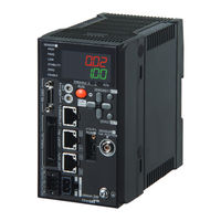
Omron ZW-CE1*T User Manual (450 pages)
ZW series Displacement Sensor Confocal Fiber Type Displacement Sensor
Brand:
Omron
| Category:
Accessories
| Size: 11.81 MB
Table of Contents
Editor's Note
9
Copyrights and Trademarks
9
Notice
10
Related Manuals
10
Table of Contents
11
Search from Settings
18
1 Basic Configuration
19
ZW-Series Displacement Sensors
20
Types of Sensor Controllers
20
Basic Operation Flow
21
2 Installation and Connections
23
System Configuration
24
Connection Compatibility
25
Part Names and Functions
27
Sensor Head
27
Calibration ROM
27
Sensor Controller
28
Front View
29
Control Panel
29
Rear View
30
Installation
32
Installation of Sensor Head
32
Installation of Sensor Controller
37
Connecting Calibration ROM
39
Connecting Fiber Cable
40
Calibrating Sensor Head
44
Wiring
46
32-Pole Extension Connector
46
Analog Output Terminal Block
48
Input Terminal Block
49
Electrical Specifications
51
Installing the Sysmac Studio
53
3 Basic Operation
55
Launching a Project
56
Connecting to the Sensor with PC Tool
56
Entering Project Information
57
Explanation of Screen Sections
58
PC Tool
58
Switching Operation Modes
63
Bank Switching
64
Multi-Task and Bank Data
64
Switching Banks
66
Perform the Zero Reset
67
Zero Reset
67
Setting Threshold Value
70
Threshold Value Settings
70
Saving a Project
72
Exporting a Project
72
Importing a Project
72
Operating with Sensor Controller
73
4 Settings for Function
75
Setting Sensing
76
Selecting the Area Mode
76
Setting the Material of the Target to Measure
77
Setting the Noise Cut Level
78
Setting Smoothing Size
79
Setting Start Direction of Count Measurement Surfaces
80
Setting Exposure Time Control Mode
81
Setting the Measurement Area
82
Setting Measurement Items
85
What Is a Measurement Item
85
Measuring the Height
85
Measuring the Thickness
87
Performing Calculations
88
Setting the Output Conditions
89
Setting Scaling
89
Setting Filters
95
Setting Hold
100
Setting the Zero Reset
107
Setting the Banks
112
Changing the Bank Mode
112
Copying the Bank/System Settings
113
Saving the Bank/System Settings
114
Clearing the Bank Settings
115
Setting the System
116
Checking Information
116
Making Sensor Settings
117
Initializing Settings
118
Displaying Measured Values in Graphs
122
Specifying the Sampling Start and End Conditions
124
Starting and Ending Sampling before and after the Trigger Condition Is Met
126
Saving Measured Values in a File
127
Outputting the Results of Sampling as a File
127
Exporting the Results of Sampling
127
Displaying Saved Measured Values
130
Performing Internal Logging
131
Storing the Light Reception Wave Form in a File
133
Recovering Calibration ROM Data
135
Printing the Contents of Settings
136
Controll Input Signal with PC Tool
137
6 Communications with External Devices
139
Parallel I/O Connection
140
I/O Signal Functions
140
Settings for Analog Output
142
Settings for Judgment Output
147
Settings for Processing When Measurement Is Not Possible
150
Settings for Bank Control
152
Settings for Internal Logging
153
Timing Chart
154
Ethercat Connection
161
Overview of Ethercat Networks
161
ZW Communications Methods in an Ethercat Connection
164
Setting Communications Specifications (Ethercat Communications)
167
List of I/O Ports for each Area (PDO Mapping) and Memory Assignments
168
Timing Chart (Ethercat)
191
Sample Ladder Program (Ethercat)
197
Sysmac Device Features
198
Ethernet/Ip Connection
200
Introduction to Ethernet/Ip
200
ZW Communications for Ethernet/Ip Connections
202
Setting Communications Specifications (Ethernet/Ip)
205
Tag Data Link Setting Methods
207
Memory Assignments and Commands
210
Timing Chart (Ethernet/Ip)
222
Sample Ladder Program (Ethernet/Ip)
227
No-Protocol Connection
228
Outline of No-Protocol Communications
228
Setting up No-Protocol Communications
229
Setting Communications Specifications (RS-232C Communications)
232
Setting for Serial Data Output after Application of Measured Value
233
Command List
237
Command Format
239
Performing Settings Offline
264
Starting a Project in Offline Mode
265
Changing between Online and Offline
266
Offline Debugging of the Sensor Control Program and Sensor Opera
267
Tion
267
Operation
267
8 Troubleshooting
271
Error Messages
272
Errors for Ethercat Connection (Sysmac Error Status)
272
Errors for Ethercat Connection (SDO)
283
Errors for Ethernet or Ethernet/Ip Connection
284
Errors Common to All Communication States
285
Troubleshooting
286
9 Sensor Controller Operations
289
Search from Menu Tree
290
FUN Mode Menu
290
RUN (Run) Mode Menu
295
Functions of Operating Keys
296
Digital Displays
297
Switching Operation Modes
298
Functions and Operations During Measurement
300
Switching the RUN (Run) Mode Display
300
Setting Sensing
304
Setting the Material of the Target to Measure
304
Setting Start Direction of Count Measurement Surfaces
305
Setting Exposure Time Control Mode
306
Setting Measurement Items
307
Measuring the Height
307
Measuring the Thickness
308
Calculating
309
Setting the Output Conditions
312
Setting the Filter
312
Setting Scaling
316
Setting Hold
320
Setting a Trigger Delay
323
Setting the Zero Reset
324
Setting the Banks
328
Switching Banks
328
Changing the Bank Mode
329
Copying the Bank Settings
330
Saving the Bank/System Settings
331
Clearing the Bank Settings
332
Setting Threshold Value
333
Teaching
333
Direct
335
Setting the System
336
Checking Information
336
Setting the Key Lock
337
Calibrating Sensor Head
338
Initializing Settings
339
Connecting Parallel I/O
340
Settings for Analog Output
340
Settings for Judgment Output
344
Settings for Processing When Measurement Is Not Possible
346
Setting for Internal Logging
348
Connecting with Ethercat
350
Setting Fieldbus
350
Setting GATE Signal on Time
351
Connecting with Ethernet/Ip
352
Network Settings of the Sensor
352
Setting Fieldbus
353
Connecting by No-Protocol Communications
354
Initial Settings for No-Protocol Communications
354
Setting Communications Specifications (RS-232C Communications)
355
Setting Serial Data Output
356
Set the Delimiter
357
10 Appendices
359
Specifications and External Dimensions
360
Sensor Head
360
Sensor Controller
372
Status Indicators
374
PC Tools (Sysmac Studio)
376
Accessories
377
EMC Directive Conformity
381
Firmware Update
382
Use PC Tools (Sysmac Studio) to Update
382
Performing the Update on Warp Engine ZW
383
Processing Item Data List
386
System Data List
390
Object Dictionary
392
Object Dictionary Area
392
Data Type
392
Description Format of Objects
393
Communication Object
394
PDO Mapping Object
397
Sync Manager Communication Object
401
Manufacturer Unique Objects
404
Index
445
Revision History
448
Advertisement
Advertisement
Related Products
Omron ZW-C1*AT
Omron ZW-C1*T
Omron ZW-5000 Series
Omron ZW Series
Omron ZW-S20
Omron ZW-S7030
Omron ZW-S5010
Omron ZW-S5020
Omron ZW-XC7
Omron ZW-8000 Series
Omron Categories
Blood Pressure Monitor
Controller
Accessories
Switch
Inverter
More Omron Manuals
Login
Sign In
OR
Sign in with Facebook
Sign in with Google
Upload manual
Upload from disk
Upload from URL