
Related Manuals for ADLINK Technology AmITX-SL-G


Summary of Contents for ADLINK Technology AmITX-SL-G
- Page 1 AmITX-SL-G User’s Manual Mini-ITX Embedded Motherboard with and 7 Gen Intel® Core™ i7/i5/i3 Processors and Intel® Q170/H110 Chipset Manual Rev.: Revision Date: September 17, 2018 Part Number: 50-1J070-1010...
- Page 2 Preface Copyright Copyright 2017, 2018 ADLINK Technology, Inc. This document contains proprietary information protected by copyright. All rights are reserved. No part of this manual may be reproduced by any mechanical, electronic, or other means in any form without prior written permission of the manufacturer.
-
Page 3: Table Of Contents
AmITX-SL-G Table of Contents Preface ..........................ii List of Figures ........................v List of Tables ........................vi Introduction ........................ 1 1.1. Packing List ........................1 1.2. Optional Accessories ...................... 1 Specifications ......................3 2.1. Core System ........................3 2.2. Rear I/O Connectors ....................... 3 2.3. -
Page 4: Preface
7.5. PCI Interrupt Routing Map .................... 43 7.6. SMBus Slave Address ....................43 BIOS Setup ....................... 45 8.1. Menu Structure......................45 8.2. Main ..........................46 8.3. Advanced ........................52 8.4. Security ......................... 68 8.5. Boot ..........................68 8.6. Save & Exit ........................70 Safety Instructions ...................... -
Page 5: List Of Figures
AmITX-SL-G List of Figures Figure 1: AmITX-SL-G Functional Block Diagram ..................9 Figure 2: AmITX-SL-G Rear I/O ......................11 Figure 3: AmITX-SL-G Component-Side Connectors ................11 Figure 4: AmITX-SL-G Mechanical Dimensions ................... 12 Figure 5: Jumper and Switch Locations ....................28... - Page 6 List of Tables Table 1: AmITX-SL-G Processors ......................1 Table 2: AmITX-SL-G Onboard Connector Information ............... 31 Table 3: SEMA Onboard Voltage Monitor .................... 35 Table 4: SEMA BMC Status ......................... 36 Table 5: SEMA Exception Codes ......................36 Table 6: SEMA BMC Flags ........................37 Table 7: System Memory Map ......................
-
Page 7: Introduction
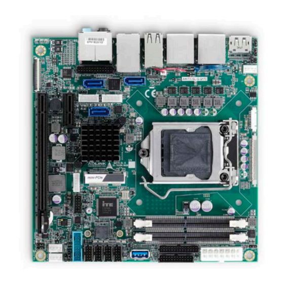
The AmITX-SL-G features three DisplayPorts, dual Gigabit Ethernet ports, USB 3.0 ports, USB 2.0 ports, SATA 6 Gb/s ports, and High Definition Audio with 7.1 channels. Expansion is provided by one PCIe x16, one PCIe x1, and two mini-PCIe slots. - Page 8 This page intentionally left blank. Introduction...
-
Page 9: Specifications
AmITX-SL-G 2. Specifications 2.1. Core System Desktop 6th Generation Intel® Core™ i7/i5/i3 and Pentium®/Celeron® Processor, LGA1151 socket Intel® Core™ i7-6700 Processor, 4C, 3.4/4.0 GHz, 8M, 65W Intel® Core™ i7-6700TE Processor, 4C, 2.4/3.4 GHz, 8M, 35W Intel® Core™ i5-6500 Processor, 4C , 3.2/3.6 GHz 6M, 65W Intel®... -
Page 10: Internal Headers And Connectors
2.3. Internal Headers and Connectors PCI Express Slots PCIe x16 (Gen3) PCIe x1 (Gen2) 1x Mini-PCIe card (default half size, full size optional), supports PCIe x1(Gen 2)/USB2.0 (top side) 1x Mini-PCIe card (default full size, half size optional): supports PCIex1(Gen 2) or mSATA/USB2.0 (bottom side) 2x USB 3.0 onboard header (Q170) 2x USB 2.0 onboard header (H110) -
Page 11: Video
AmITX-SL-G 2.7. Video GPU Feature Support Intel® 9th generation LP graphics core architecture with up to 18 execution units supporting DirectX 11/12, OGL4.3/4.4, and up to three independent, simultaneous displays • 3x DisplayPort v1.2 with resolution up to 4096 x 2160 @ 24Hz (3x DisplayPort(Q170) ,... - Page 12 2.11.1. Power Consumption Processor Intel® Core™ Intel® Core™ Intel® Core™ Intel® Core™ Intel® Core™ Intel® Core™ i7-7700 i7-6700 3.40 i3-7101E 3.90 i7-7700T 2.90 i5-7500T i3-7101TE 3.60Ghz 2.70Ghz 3.40Ghz Chipset H110 H110 H110 H110 H110 H110 Transcend Transcend Transcend Transcend Transcend Transcend Memory TS512MSH64...
- Page 13 AmITX-SL-G Processor Intel® Core™ Intel® Core™ Intel® Core™ Intel® Core™ Intel® Core™ Intel® Core™ i7-7700 i7-6700 3.40 i3-7101E 3.90 i7-7700T 2.90 i5-7500T i3-7101TE 3.60Ghz 2.70Ghz 3.40Ghz 12V(A) 6.65 5.75 4.58 4.25 3.34 3.32 5VSB(A) Power 79.8 54.96 40.08 39.84 consumption(W) Windows MAX mode/Enable EIST 3.3V(A)
-
Page 14: Temperatures
Processor Intel® Core™ Intel® Core™ Intel® Core™ Intel® Core™ Intel® Core™ Intel® Core™ i7-7700 i7-6700 3.40 i3-7101E 3.90 i7-7700T 2.90 i5-7500T i3-7101TE 3.60Ghz 2.70Ghz 3.40Ghz Power 0.35 0.35 consumption(W) S5 Mode with ECO Disable 3.3V(A) 5V(A) 12V(A) 5VSB(A) 0.06 0.06 0.07 0.06 0.06... -
Page 15: Functional Block Diagram
COM3 Header 3x RS-232 COM4 Header SPI0/1 Header IT8783 StI 0/1 SPI0 SPI1 Socket PS/2 Failsafe switch Atmel CPU FAN (optional) Sa.us SYS FAN1 SYS FAN2 Sensor LM73 GPIO Feature Connector System Signals Figure 1: AmITX-SL-G Functional Block Diagram Specifications... - Page 16 This page intentionally left blank. Specifications...
-
Page 17: Mechanical Layout
AmITX-SL-G 3. Mechanical Layout 3.1. Connector Locations 3.1.1. Rear I/O Connectors USB 3.0 USB 3.0 USB 2.0 LAN Audio Figure 2: AmITX-SL-G Rear I/O 3.1.2. Component-Side Connectors SATA Connectors Audio Header CPU Fan DB40 Connector Mini PCIe PCIe x1 LVDS AUX... -
Page 18: Mechanical Dimensions
3.2. Mechanical Dimensions Top View 28.21 35.34 36.41 59.54 61.09 74.24 74.24 149.24 157.48 157.48 Side View 35.33 27.58 Dimensions: mm Figure 4: AmITX-SL-G Mechanical Dimensions Mechanical Layout... -
Page 19: Thermal Solutions
AmITX-SL-G 3.3. Thermal Solutions LGA1150 CPU Cooler, H=30.0mm, 45W Standard Temp.: 0°C to 60°C P/N: 32-20513-0000 LGA1150 CPU Cooler, H=46.05mm, Standard Temp.: 0°C to 60°C P/N: 32-20512-0000 LGA1150 CPU Cooler, H=50.2mm, 95W Standard Temp.: 0°C to 60°C P/N: 32-20113-3000 LGA1150 CPU Cooler, H=61.4mm, 95W Standard Temp.: 0°C to... - Page 20 This page intentionally left blank. Mechanical Layout...
-
Page 21: Connectors And Jumpers
AmITX-SL-G 4. Connectors and Jumpers See 3.1 Connector Locations on page 12. 4.1. Rear IO Connectors 4.1.1. DisplayPort Three DisplayPort v1.2 specification ports up to 3840x2160 @ 60 Hz Pin # Signal Pin # Signal CN_DP0_P Ground CN_DP0_N CN_DP1_P Ground... - Page 22 LED1 (Speed) LED2 (Link/Activity) Status Description Status Description 10 Mb No Link connection Green 100 Mb Orange Linked connection Orange 1 Gb connection Blinking Data Activity 4.1.3. USB Connectors 4x USB 3.0, 4x USB 2.0 5V supply for external devices ...
-
Page 23: Internal Connectors
AmITX-SL-G 4.2. Internal Connectors 4.2.1. ATX Power Connector (ATX_PWR, proprietary) AmITX-SL-G supports a proprietary internal ATX Power Connector (ATX_PWR). An adapter cable is provided for conection to a standard ATX power supply. Pin # Signal Pin # Signal SB5V P_OK... - Page 24 4.2.2. SATA Connectors (SATA1/2/3) Three SATA 6 Gbps ports are available on the AmITX-SL-G. • Option function: Jumper select NA/3.3V/5V for SATA1 and SATA2 to deliver power by SATA pin7, Default is Pin # Signal N/A(default), (option)SATA1/2 SATA DOM 4.2.3.
- Page 25 AmITX-SL-G 4.2.4. USB Header 5V/SB5V: 5V supplies for external devices. SB5V is supplied during power down to allow wakeup on USB device activity during S3~S4 state. H110: 2xUSB2.0: Pin # Signal Pin # Signal P5V_USB P5V_USB P2_DN_R- P3_DN_R P2_DP_R P3_DP_R USB Cable (optional): USB 2.0 Header to 2x Female Type-A Cable (length 200mm), P/N: 30-20874-1000...
- Page 26 Q170: 2xUSB3.0 Pin # Signal Pin # Signal USB3_TX_P5 USB3_TX_P6 USB3_TX_N5 USB3_TX_N6 USB3_RX_P5 USB3_RX_P6 USB3_RX_N5 USB3_RX_N6 USB2_P7 USB2_P8 USB2_N7 USB2_N8 P5VA_PH P5VA_PH USB Cable (optional): USB 3.0 Header to 2x Female Type-A Cable (length 200mm), P/N: 30-20963-0000 Connectors and Jumpers...
- Page 27 AmITX-SL-G 4.2.5. PS/2 Keyboard and Mouse Connector 6 pin 2.0 pitch standard wafer connector. No support for PS/2 KB/MS wake function Pin # Signal MSCLK V5S_S3 MSDATA KBDATA KBCLK KB/MS Cable (optional): PS/2 KB/MS Cable (length 400mm), P/N: 30-20873-0000 4.2.6.
- Page 28 4.2.7. CPU Fan and System Fan Connectors Pin 3 and 4 are connected (monitored and managed) by SEMA controller. Pin # Signal Fan Power (+12V) Fan Sense Fan Speed Control 4.2.8. Serial COM Port Connectors Four internal Serial Ports (SER1-4) Serial Port Functions SER1...
- Page 29 AmITX-SL-G RS-485 (SER1 only) Pin # Signal Pin # Signal Tx/Rx- Tx/Rx+ — — — — — — 5V / 12V SER1 Mode Switch (SWS1M) SWS1M (SER1 Mode Select) RS-232 RS-422 RS-485 (default) Note: See Section 4.3 COM Port (SER1) Mode Selection (SWS1M). Use JPS3P2 for SER1 power selection.
- Page 30 Note Type Signal Pin # Pin # Signal Type Note LVDS LVDS A0- LVDS B1+ LVDS LVDS LVDS A0+ POWER GND PWR Max. 0.5A LVDS LVDS A1- LVDS B2- LVDS LVDS LVDS A1+ LVDS B2+ LVDS LVDS LVDS A2- LVDS BCLK- LVDS LVDS LVDS A2+ LVDS BCLK+...
- Page 31 AmITX-SL-G 4.2.11. Front Panel Connector 2x12-pin 2.0 pitch standard wafer connector The front panel connector provides Audio Mic-In / Line Out, ATX power switch, Reset, HDD LED, and SUS LED (System Power LED). Pin # Signal Ioh/ Iol Type Note Pin # Signal...
- Page 32 Pin # Signal Pull U/D IOH/IOL Type Note Pin # Signal Type IOH/IOL Pull U/D Note SB3V3 PWR - PWR - GPIO0 PU10K3V3 IOT GPIO1 PU10K3V3 GPIO2 PU10K3V3 IOT GPIO3 PU10K3V3 GPIO4 PU10K3V3 IOT GPIO5 PU10K3V3 GPIO6 PU10K3V3 IOT GPIO7 PU10K3V3 GPIO8 PU10K3V3 IOT...
- Page 33 AmITX-SL-G 4.2.14. DB40 Debug Board Connector FPC Connector Type: FCI 59GF Flex 10042867 Interface Signal Remark Interface Signal Remark VCC_SPI_IN SPI Power Input from TXD6 flash tool to module. HW Program Program need add MOS FET to interface interface switch SPI power for SPI...
-
Page 34: Jumper And Switch Settings
4.3. Jumper and Switch Settings LVDS Backlight active BIOS Switch High/Low Enable (JPL5) (SW2) LVDS Backlight Power (JPL4) SATA 1/2 DOM Power Selection (JPL11) LVDS Panel Power Clear CMOS (JPL6/JPL8) (CMOS) SER1 Mode Switch (SWS1M1) SER1 Power Selection (JPS3P2) Mini-PCIe/mSATA Selection (JPMSATA2) ATX/AT Mode Jumper (JPATX) - Page 35 AmITX-SL-G 4.3.4. COM Port (SER1) Mode Selection Switch (SWS1M) SWS1M (SER1 Mode Select) RS-232 RS-422 RS-485 (default) 4.3.5. COM Port (SER1) Power Selection Jumper (JPS3P2) JPS3P2 SER1 Power NC (default) 4.3.6. LVDS Backlight Power Selection Jumper (JPL4) JPL4 Backlight Power 5V (default) 4.3.7.
- Page 36 BIOS Switch Setting (SW2) Fail Safe SPI0 + SPI1 (default ) Boot from on board Boot from socket BIOS BIOS (Default) Normal BIOS Mode Failsafe BIOS Mode (Default) Default: 1 ON and 2 OFF (Boot from on board BIOS and enable failsafe) 4.3.9.
-
Page 37: Onboard Connector Information
AmITX-SL-G 4.4. Onboard Connector Information Table 2: AmITX-SL-G Onboard Connector Information Onboard Connector Mating Connector Connector Manufacturer Part No. Manufacturer Part No. ADLINK Cable 23N6850-10S10B-01G-B- YY-1970H-2*5P 30-20876- COM Port SER1-4 YOUNG YAK (PH2.0) 0000 (optional) ATX power ATX_PW Molex 39-28-1143 E.C.I... - Page 38 This page intentionally left blank. Connectors and Jumpers...
-
Page 39: Driver Installation
AmITX-SL-G 5. Driver Installation Drivers can be downloaded through the following link. https://www.adlinktech.com/Products/Industrial_Motherboards_SBCs/Mini-ITXEmbeddedBoards/AmITX-SL- G?lang=en Driver Installation... - Page 40 This page intentionally left blank. Driver Installation...
-
Page 41: Smart Embedded Management Agent (Sema)
AmITX-SL-G 6. Smart Embedded Management Agent (SEMA) The onboard microcontroller (BMC) implements power sequencing and Smart Embedded Management Agent (SEMA) functionality. The microcontroller communicates via the System Management Bus with the CPU/chipset. The following functions are implemented. • Total operating hours counter. Counts the number of hours the module has been run in minutes. -
Page 42: Table 4: Sema Bmc Status
6.1.2. Main Current The BMC implements a current monitor. The current can be read by calling the SEMA function “Get Main Current”. The function returns four 16-bit values divided in high-byte (MSB) and low-byte (LSB). These 4 values represent the last 4 currents drawn by the board. The values are sampled every 250ms. The order of the 4 values is NOT in chronological order. -
Page 43: Table 6: Sema Bmc Flags
AmITX-SL-G Exception Error Message Code NO_3V3_A_PGD NO_VDDQ_PG NO_P_5V_3V3_S0_PG NO_1V0_A_PG NO_VCORE_PG NO_5V_STBY_PG NO_5V_STBY_PG 6.1.5. BMC Flags The BMC Flags register returns the last detected Exception Code since power-up and shows the BIOS in use and the power mode. Table 6: SEMA BMC Flags... - Page 44 This page intentionally left blank. Smart Embedded Management Agent (SEMA)
-
Page 45: System Resources
AmITX-SL-G 7. System Resources 7.1. System Memory Map Table 7: System Memory Map Address Range (decimal) Address Range (hex) Size Description (4GB-2MB) FFE00000 – FFFFFFFF 2 MB High BIOS Area (4GB-18MB) – (4GB-17MB-1) FEE00000 – FEEFFFFF 1 MB MSI Interrupts (4GB-20MB) –... -
Page 46: Interrupt Request (Irq) Lines
Hex Range Device Slave PIC Edge/Level Trigger register 0A00~0AFF Reserved for SIO functions base address (ex: PME /GPIO etc) CF8-CFB PCI configuration address register (32 bit I/O only) Reset Control register (8 bit I/O) CFC-CFF PCI configuration data register 7.3. Interrupt Request (IRQ) Lines 7.3.1. -
Page 47: Table 10: Irq Lines Apic Mode
AmITX-SL-G 7.3.2. IRQ Lines APIC Mode Table 10: IRQ Lines APIC Mode IRQ# Typical Interupt Resource Connected to Pin Available Counter 0 Keyboard controller Cascade interrupt from slave PIC Serial Port 2 (COM2) IRQ3 via SERIRQ / PIRQ Note (1) -
Page 48: Pci Configuration Space Map
7.4. PCI Configuration Space Map Table 11: PCI Configuration Space Map Device Function Routing Description Number Number Number Intel Host Bridge Intel PEG port Internal Intel I.G.D. Internal System device Internal xHCI Controller Internal Data Acqusition Internal Intel Management Engine Interface #1 Internal Intel Serial Device Internal... -
Page 49: Pci Interrupt Routing Map
AmITX-SL-G 7.5. PCI Interrupt Routing Map Table 12: PCI Interrupt Routing Map P.E.G Audio xHCI Controller Controller Line Root Controller Controller #1 Controller Port Int0 INTA:16 INTA:16 INTA:16 INTA:16 INTA:16 INTA:16 Int1 INTB:17 INTB:17 Int2 INTC:18 INTC:18 Int3 INTD:19 INTD:19... - Page 50 This page intentionally left blank. System Resources...
-
Page 51: Bios Setup
AmITX-SL-G 8. BIOS Setup 8.1. Menu Structure This section presents the six primary menus of the BIOS Setup Utility. Use the following table as a quick reference for the contents of the BIOS Setup Utility. The subsections in this section describe the submenus and setting options for each menu item. -
Page 52: Main
8.2. Main The Main Menu provides read-only information about your system and also allows you to set the System Date and Time. Refer to the tables below for details of the submenus and settings. 8.2.1. Main > System Information Feature Options Description Project Version... - Page 53 AmITX-SL-G 8.2.5. Main > System Management > Board Information Board Information Info only SEMA Firmware Read only Display SEMA firmware Build Date Read only Display SEMA firmware build date SEMA Boot loader Read only Display SEMA boot loader Build Date...
- Page 54 8.2.7. Main > System Management > Power Consumption Feature Options Description Power Consumption Info only VCORE Read only Display actual VCORE voltage VGFX Read only Display actual VGFX voltage VMEM Read only Display actual VMEM voltage Read only Display actual RTC voltage 3.3V Read only Display actual 3.3V voltage...
- Page 55 AmITX-SL-G 8.2.9. Main > System Management > Flags Feature Options Description Flags Info only BMC Flags Read only BIOS Select Read only Display the selection of current BIOS ROM. ATX/AT-Mode Read only Display ATX/AT-Mode. Exception Code Read only System exception reason.
- Page 56 8.2.12. Main > System Management > Smart Fan Feature Options Description Smart Fan Info only CPU Smart FanTemperature CPU Sensor Select CPU smart fan source Source System Sensor CPU Fan Mode AUTO (Smart Fan) Select CPU fan mode Fan Off Fan On Trigger Point 1 Read only...
- Page 57 AmITX-SL-G Feature Options Description Trigger Point 3 Read only Trigger Temperature Specifies the temperature threshold at which the BMC turns on System fan1 the specified PWM level PWM Level Select PWM level Trigger Point 4 Read only Trigger Temperature Specifies the temperature threshold at which the...
-
Page 58: Advanced
8.2.14. Main > System Date and Time Feature Options Description System Date Weekday, MM/DD/YYYY Requires the alpha-numeric entry of the day of the week, day of the month, calendar month, and all 4 digits of the year, indicating the century and year (Fri XX/XX/20XX) System Time HH/MM/SS... - Page 59 AmITX-SL-G Feature Options Description VT-d Disabled VT-d capability Enabled Intel(R) Speed Shift Technology Disabled Enable/Disable Intel(R) Speed Shift Technology support. Enabling will expose the CPPC v2 interface Enabled to allow for hardware controlled P-states. Intel(R) SpeedStep(tm) Disabled Enabled/Disabled Intel SpeedStep.
- Page 60 8.3.2. Advanced > Audio Feature Options Description Audio HD Audio Disabled Control Detection of the HD-Audio device. Disabled = Enabled HDA will be unconditionally disabled. Enabled = HDA Auto will be unconditionally enabled. Auto = HDA will be enabled if present, disabled otherwise.
- Page 61 AmITX-SL-G 8.3.4. Advanced > Thermal Feature Options Description Thermal DTS SMM Enabled Disabled: ACPI thermal management uses EC reported temperature values.Enabled: ACPI thermal Disabled management uses DTS SMM mechanism to obtain CPU temperature values.Out of Spec: ACPI Thermal Management uses EC reported temperature values and DTS SMM is used to handle Out of Spec condition.
- Page 62 8.3.5. Advanced > Memory Feature Options Description Memory RC Version Info only Display memory RC version Memory Frequency Info only Display memory frequency Total Memory Info only Display tatal system memory size DIMM#1 Info only Display DIMM#1 status Size Info only Display DIMM#1 Size DIMM#2 Info only...
- Page 63 AmITX-SL-G 8.3.6. Advanced > Graphics Feature Options Description IGFX VBIOS version Info only Graphics Turbo IMON Current Graphics turbo IMON current values supported(14-31). Primary Display Auto Select which of Auto/IGFX/PEG/PCIE Graphics device should be Primary Display. IGFX PCIE Primary PEG...
- Page 64 Feature Options Description Gfx Low Power Mode Enabled This option is applicable for SFF only. Disabled LVDS Backlight Mode PCH Control Select LVDS Backlight Control function. BMC Control GTT LVDS Backlight Control GTT LVDS Backlight Control. 100% Primary IGFX Boot Display VBIOS Default Select the Video Device which will be activated during POST.
- Page 65 AmITX-SL-G Feature Options Description Data format and Color Depth VESA 24 bpp Data format and Color Depth select JEIDA 24 bpp JEIDA/vesa 18 bpp LVDS Output Mode Single LVDS bus Single/Dual mode select Dual LVDS bus DE Polarity Active High...
- Page 66 Feature Options Description USB transfer time-out 1 sec The time-out value for Control, Bulk, and Interrupt transfers. 5 sec 10 sec 20 sec Device reset time-out 10 sec USB mass storage device start unit command time- out. 20 sec 30 sec 40 sec Device power-up delay Auto...
- Page 67 AmITX-SL-G 8.3.10. Advanced > PCI and PCIe Feature Options Description PCI Common Settings Info only PERR# Generation Disabled Enable/Disable PCI Device to Generate PERR#. Enabled SERR# Generation Disabled Enable/Disable PCI Device to Generate SERR#. Enabled PEG Port Configuration ► Submenu PCI Express Configuration ►...
- Page 68 8.3.12. Advanced > PCI Express Configuration Feature Options Description PEG Port Configuration Info only PCI Express Root Port 5 ► Submenu PCI Express Root Port 5 Settings PCI Express Root Port 6 ► Submenu PCI Express Root Port 6 Settings PCI Express Root Port 7 ►...
- Page 69 AmITX-SL-G 8.3.15. Advanced > Serial Port [1-4] Configuration Feature Options Description Serial Port [1-4] Configuration Info only Serial Port Disabled Enable or Disable Serial Port (COM) Enabled Device Settings Info only Change Setting Auto Select an optimal settings for Super IO Device Change IO and IRQ 8.3.16.
- Page 70 Feature Options Description Console Redirection Disabled Console Redirection enable or disable. Enabled Console Redirection Settings ► Submenu The settings specify how the host computer and the remote computer (which the user is using) will exchange data. Both computers should have the same or compatible settings.
- Page 71 AmITX-SL-G Feature Options Description Redirection After BIOS Post Always Enabled The Settings specify if BootLoader is selected, then legacy console redirection is disabled before booting BootLoader to legacy OS. Default value is Always Enable which means legacy console redirection is enabled for legacy OS.
- Page 72 8.3.20. Advanced > Network Feature Options Description Network Info only Network Stack Disabled Enable/Disable Network Stack. Enabled PCH LAN i219LM Controller Disabled Control i219 Lan support. Enabled Wake on LAN Disabled Enable or disable integrated LAN to wake the system. (The Wake On LAN cannot be disabled if Enabled ME is on at Sx state.) PCH LAN i211 Controller...
- Page 73 AmITX-SL-G 8.3.21. Advanced > Security Feature Options Description Security Info only Intel TXT(LT) Support Disabled Enables or Disables Intel(R) TXT(LT) support. Enabled Security Configuration BIOS Security Configuration settings. Trusted Computing Trusted Computing Settings. 8.3.22. Advanced > Security > Security Configuration...
-
Page 74: Security
8.3.24. Advanced > Miscellaneous Feature Options Description Miscellaneous Info only Chassis Intrusion Support Enabled Chassis Intrusion Support Disabled 8.4. Security 8.4.1. Security > Password Description Feature Options Description Administrator Password Enter password User Password Enter password Secure Boot menu ► Submenu Customizable Secure Boot settings. - Page 75 AmITX-SL-G Feature Options Description Boot Option Priorities Info only Fast Boot Disabled Enables or disables boot with initialization of a minimal set of devices required to launch active boot Enabled option. Has no effect on BBS boot options. New Boot Option Policy...
-
Page 76: Save & Exit
8.6. Save & Exit Feature Options Description Save Options Info only Save Changes and Exit Yes No Exit system setup after saving the changes. Discard Changes and Exit Yes No Exit system setup without saving any changes. Save Changes and Reset Yes No Reset the system after saving the changes. -
Page 77: Safety Instructions
AmITX-SL-G Safety Instructions Read and follow all instructions marked on the product and in the documentation before you operate your system. Retain all safety and operating instructions for future use. • Please read these safety instructions carefully. • Please keep this User‘s Manual for later reference. -
Page 78: Getting Service
5215 Hellyer Avenue, #110, San Jose, CA 95138, USA Tel: +1-408-360-0200 Toll Free: +1-800-966-5200 (USA only) Fax: +1-408-360-0222 Email: info@adlinktech.com ADLINK Technology (China) Co., Ltd. Address: 300 Fang Chun Rd., Zhangjiang Hi-Tech Park, Pudong New Area Shanghai, 201203 China Tel: +86-21-5132-8988 Fax: +86-21-5132-3588 Email: market@adlinktech.com...
Need help?
Do you have a question about the AmITX-SL-G and is the answer not in the manual?
Questions and answers