Sign In
Upload
Manuals
Brands
ADLINK Technology Manuals
Motherboard
CoreModule 430
ADLINK Technology CoreModule 430 Manuals
Manuals and User Guides for ADLINK Technology CoreModule 430. We have
1
ADLINK Technology CoreModule 430 manual available for free PDF download: Reference Manual
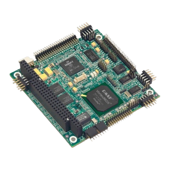
ADLINK Technology CoreModule 430 Reference Manual (56 pages)
PC/104 Single Board Computer
Brand:
ADLINK Technology
| Category:
Motherboard
| Size: 1 MB
Table of Contents
Table of Contents
3
Chapter 1 About this Manual
7
Purpose of this Manual
7
References
7
Chapter 2 Product Overview
9
PC/104 Architecture
9
Figure 2-1. Stacking PC/104 Modules with the Coremodule 430
9
Product Description
10
Module Features
10
Block Diagram
13
Figure 2-2. Block Diagram
13
Major Components (Ics)
14
Table 2-1. Major Components (Chips) Descriptions and Functions
14
Figure 2-3. Component Locations (Top Side)
15
Header, Connector, and Socket Definitions
16
Figure 2-4. Connector Pin Identifications
16
Table 2-2. Header, Connector, and Socket Descriptions
16
Figure 2-5. Header Locations (Top Side)
17
Jumper Header Definitions
17
Table 2-3. Jumper Settings
17
Specifications
18
Physical Specifications
18
Mechanical Specifications
18
Figure 2-6. Mechanical Dimensions (Top Side)
18
Table 2-4. Weight and Footprint Dimensions
18
Power Specifications
19
Environmental Specifications
19
Thermal/Cooling Requirements
19
Table 2-5. Power Supply Requirements
19
Table 2-6. Environmental Requirements
19
Chapter 3 Hardware
21
Overview
21
Cpu
22
Graphics
22
Memory
22
System Memory
22
Video Memory
22
SPI Flash
22
Memory Map
23
Table 3-1. Memory Map - Vortex 86SX/DX Processor
23
Interrupt Channel Assignments
24
Table 3-2. Interrupt Channel Assignments
24
I/O Address Map
25
Parallel Interface (LPT)
26
Serial Interface
27
Figure 3-1. RS-485 Serial Port Implementation
27
Table 3-6. Serial Ports 1 & 2 Interface Pin/Signal Descriptions (J3, J9)
28
USB Interface
29
Utility Interface
30
Keyboard
30
Mouse
30
Battery
30
Reset Switch
30
Speaker
30
Ethernet Interface
31
Video (TTL/VGA) Interface
32
Serial Peripheral Interface (SPI)
34
Low Pin Count Interface (LPC)
34
Miscellaneous
34
Real Time Clock (RTC)
34
User GPIO Interface
35
Oops! Jumper (BIOS Recovery)
35
Figure 3-2. Oops! Jumper
35
Remote Access
36
Remote Access Setup
36
Hot (Serial) Cable
36
Watchdog Timer
36
Figure 3-3. Hot Cable Jumper
36
Power Interface
37
Chapter 4 BIOS Setup
39
Introduction
39
Entering BIOS Setup (Local Display)
39
Entering BIOS Setup (Remote Access)
39
OEM Logo Utility
40
Logo Image Requirements
40
BIOS Setup Screens
41
BIOS Main Setup Screen
41
Figure 4-1. BIOS Main Setup Screen
41
BIOS Advanced Setup Screen
42
Figure 4-2. BIOS Advanced Setup Screen
42
BIOS Pcipnp Setup Screen
44
Figure 4-3. BIOS Pcipnp Setup Screen
44
BIOS Boot Setup Screen
46
Figure 4-4. BIOS Boot Setup Screen
46
BIOS Security Setup Screen
47
Figure 4-5. BIOS Security Setup Screen
47
BIOS Chipset Setup Screen
48
Figure 4-6. BIOS Chipset Setup Screen
48
BIOS Exit Setup Screen
51
Figure 4-7. BIOS Exit Setup Screen
51
Appendix A Technical Support
53
Table A-1. Technical Support Contact Information
53
Index
55
Advertisement
Advertisement
Related Products
ADLINK Technology CoreModule 740
ADLINK Technology CoreModule 720
ADLINK Technology CoreModule 730
ADLINK Technology CoreModule 920
ADLINK Technology CoreModule 745
ADLINK Technology AmITX-AL-I
ADLINK Technology AmITX-ALN
ADLINK Technology AmITX-BE-G
ADLINK Technology AmITX-BT-I
ADLINK Technology AmITX-BW-I
ADLINK Technology Categories
Computer Hardware
Motherboard
PCI Card
Control Unit
Desktop
More ADLINK Technology Manuals
Login
Sign In
OR
Sign in with Facebook
Sign in with Google
Upload manual
Upload from disk
Upload from URL