Table of Contents
Advertisement
Quick Links
Advertisement
Table of Contents

Related Manuals for Sanwa MT-44


Summary of Contents for Sanwa MT-44
- Page 1 ( 90478 )
- Page 2 Don’t place a piano wire close to the chassis. If the receiver or a servo ☆ sinks in the water, immediately collect it and dry the interior. When the interior is dry,please submit it to the Sanwa Service for inspection even if it performs normally. 1...
- Page 3 Warning Precaution For Operating RC Car Note About Handling the Transmitter When operating an RC car, please make sure to follow the Don't hit, drop or subject to strong impact.Touching the following notes and avoid giving trouble to others. transmitter, receiver, servos or FET speed controller with a Maintain the body of the car (boat) in a perfect condition hand stained with tire traction agent can cause malfunction or deforming the case.
- Page 4 Safe Handling of R/C System and Precautions Note Precautions to Use the Product Safely ● 2.4 GHz frequency band is not only used for radio control. This frequency band is shared with ISM (Industry, Science and Medical) band. It can be affected by microwave ovens, wireless LAN, digital cordless telephones, audio equipment, Bluetooth of game machines or cell phones and short-range communication such as VICS.
- Page 5 INDEX ■ Layout and Specification of the Set ・ ・ ・ ・ ・ ・ ・ ・ ・ ・ ・ ・ ・ ・ ・ ・ ・ ・ ・ ・ ・ ・ ・ ・ ・ ・ ・ ・ 5 ● Layout of the Set (5) ●...
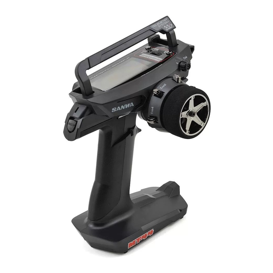
- Page 6 Names of each part of the transmitter Carrying handle (Movable) Display Panel *LED will be on when Telemetry is ON and Receiver Battery is OFF. LED will be flashing while Telemetry alram is active. Select Button Multi-Selector 送 Back Button 信...
- Page 7 Power Switch 送 Trigger Position 信 Adjusting Screw 機 各 部 の When using the Strap Hook 名 称 Antenna interior Micro SD cover Strap Hook Remove the screw, attach the hook and tighten the screw. *Make sure that the hook is facing the right direction. Grip Throttle Trigger (Normal/Small)
- Page 8 Structure and the Standard of the Set Structure of the Set RX-482 PC (Primary Component) Transmitter TX-471 Receiver RX-482 Servos Accessories Strap Hook x 1 Trigger Angle Spacer x 1 Brake Trigger +1/+2 x each 1 Grip Pad S size x 1 Receiver Dust Cover x 1 Switch Harness x 1 Instruction Manual x1...
-
Page 9: Before Using
Before using Adjusting the steering and throttle tension With MT-44, the user can easily adjust the tension of the steering/throttle trigger to match operation of the steering/throttle to the user’s preference. Adjusting the steering tension By inserting a hexagon wrench driver (1.5mm) to the place where the arrow is... - Page 10 Before using Adjusting the full adjustable trigger Adjusting the trigger position Loosen the fixing screws of the trigger on the back of the transmitter. Then, adjust the adjusting screw of the trigger position on the back of the transmitter to set the trigger at the position of your preference.
- Page 11 Connector Cover About Micro SD Card MT-44 is compatible to Micro SD Cards. By using a Micro SD Card, it is possible to save model data and telemetry data. ● Also, it is possible to do firmware update using a Micro SD Card when a firmware update of MT-44 is released.
- Page 12 About connection and installation of the receiver About the receiver ●RX-471(Example) Condition of the Receiver LED BIND Button When receiving a signal Blue light is on When it cannot receive a signal BATT Blue light flashes. while setting up BIND CH4:4ch Blue light flashes rapidly.
- Page 13 For R/C System parts such as the transmitter, receiver, servos, FET Speed Controller and transmitter battery, use genuine SANWA products. When combining products other than genuine SANWA products, modifying, adjusting or exchanging parts is done at a place other than SANWA, we do not take any responsibility.
- Page 14 About Power On Alarm ● MT-44 displays “No Operation” with a warning alarm after 10 minutes of no operation of the steering wheeel, throttle trigger and switches. Alarm is turned off, if the steering wheel, throttle trigger or a switch is operated.
- Page 15 About the Display Panel ● Each feature of MT-44 allows you to directly select a feature with the Multi-Selector. ● You can set up each channel feature separately. ● As you turn the power switch on, the top screen launches after the boost screen is displayed(when the boot setting is on).
- Page 16 Usage of each feature About the Menu structure ● The user can set up features and do model memory call easily by using each key. ● The Menu consists of Setting, AUX, Model, Timer, Telemetry and System Menu, and related features are included in each menu.
- Page 17 About Short Cut Menu MT-44 has a feature of Short Cut Menu that is launched as the user performs key operation when operating the power switch. If you turn the power switch on while pressing the Back Button, it becomes the Direct Model Select and if you turn the power switch on while doing Enter operation, the Quick Setup feature launches.
- Page 18 Usage of each feature About Short Cut Menu Quick Setup <QUICK SETUP WIZARD> ● Quick Setup 1) Turn the power switch on while doing Enter operation Power Switch ON Push ⇒ Holding ENTER BACK 2) Quick Setup screen is displayed. As you do Enter operation, Quick Setup Wizard is launched.
- Page 19 ● SSR mode works only for SRG Servos, SUPER VORTEX/SV-PLUS series, HV-12, STOCK SPECIAL and HV-01. ● MT-44 will not be SSR mode by using RX-451R to BIND with SHR display. It works as the display shows. ● With SHR/SSR mode, BL-RACER, BL-FORCE, F2000, F2200. F3000 F3300, SBL-01 02 and 03CL do not work.
- Page 20 Usage of each feature Dual Rates [D/R] SETTING ● You can adjust rudder angle when operating the steering wheel and throttle trigger to their peak. To correspond to the RC car or road condition, adjust the rudder angle as you operate. *You can adjust steering for both right and left at the same time and throttle separately for high and brake sides.
- Page 21 SPEED SETTING ● Features to control the speed of the servos used for steering and throttle. By setting, the RC car is not affected even when doing a sudden operation. On the steering side, smooth corner work becomes possible and on the throttle side, stable rising from a corner by throttle work with saved power.
- Page 22 Usage of each feature Curve [CURVE] Setting/SETTING st operation of the steering ●Features to change the operating quantity of the servos again wheel/throttle trigger. When the setting value is on the plus (+) side, it responds quickly, when on the minus side (-), it responds mildly. ●...
- Page 23 [TH] Throttle Exponential ● You can change the throttle feature from Mild to Linear and to Quick. In general, when operating on a slippery road or if you find over powering, change the setting to the minus side and when operating on a high-grip road or if you find lack of power i n the power unit, change to the plus side.
- Page 24 Usage of each feature CURVE SETTING [ST] Steering Adjustable Rate Control ● You can change the steering feature from Mild to Linear and to Quick. In general, if you find your RC car oversteering, change the setting to the minus side and if you find understeering, change to the plus side. Steering Adjustable Rate Control is a simultaneous setting for L and R.
- Page 25 AUX1 Adjustable Rate Control [AUX1] ●You can change the AUX1 performance feature from Mild to Linear and to Quick. You can set the High side and the Low side separately. *When setting AUX1 to [CODE5/CODE10] in AUX TYPE, changing the setting does not affect the performance. 1) Select AUX1 with the Select button and set CURVE TYPE of AUX1 to [ARC] with the multi-selector.
- Page 26 Usage of each feature Fail Safe [F/S] SETTING ●Fail Safe Operation is a feature to keep the servos in a predetermined position for each channel in the event that the receiver cannot receive a signal from the transmit ter. A feature to keep the servos in a predetermined position for the servo of the throttle channel (2ch) in the event that the battery voltage on the receiver side of an engine RC car goes below the set voltage is Battery Fail Safe Operation.
- Page 27 BASE SETTING ● Base [BASE] is a feature to integrate features of the Reversethat determines the direction of the servo of each channel and the speed controller according to a specific RC car, the Sub Trim that adjusts the neutral position and the End Point Adjustment [EPA] that sets the operating quantity into one feature (Base) to allow you to make a setting all at once.
- Page 28 Usage of each feature BASE SETTING ●Base [BASE] is a feature to integrate features of Sub Trim that adjusts the direction of the servo of each channel and the speed controller according to a specific RC car and the End Point Adjustment [EPA] that sets the operating quantity into one feature (Base) to allow you to make a setting all at once.
- Page 29 [AUX1-EPA] AUX1 End Point Adjustment ●You can use AUX1 for functions of accessories and adjust the maximum steering angle (operating quantity) with EPA. Since you can set H/L separately, precise adjustment is possible. *When setting AUX1 to [CODE5/CODE10] in AUX TYPE, the operation will not be refected even by adjusting EPA. 1) Before adjusting AUX1 End Point Adjustment (AUX1-EPA), make a neutral adjustment of the servo (P.
- Page 30 Usage of each feature TRIM SETTING ● For Trim, you can adjust Trim for each channel and set the Trim action (center/parallel). TRIM ●Correct neutral (center) of each channel (ST/TH/AUX1/AUX2) with Trim. ●As default, steering is set for Trim 1 (TRM1), and throttle for Trim 2 (TRM2). 1) Select a channel (ST/TH/AUX1/AUX2) for adjusting Selecting a channel with the Select button Trim with the Select button.
- Page 31 CONVERT ●A feature to convert Trim that has been adjusted in each channel to Sub Trim and EPA and to correct Trim to center. Depending on a setting, there is a case you cannot convert. 1) Select a channel (ST/TH/AUX1/AUX2) to convert with the Select button.
- Page 32 Usage of each feature THROTTLE FUNCTION /TH-FUNCTION ●The throttle function allows you to adjust the setting values of ALB (Anti-Lock Brake), OFFSET and TH TYPE (throttle type) of the throttle channel. Anti-Lock Brake[ALB] THROTTLE FUNCTION/TH-FUNCTION ● Anti-Lock Brake enables stable braking on a low grip road. ●...
- Page 33 OFFSET THROTTLE FUNCTION/TH-FUNCTION ● By moving the position of the throttle neutral at the time of starting an engine RC car engine, it improves the start-up performance of the engine. ● You can fix at a position where idling speed is increased so that the engine will not stop during refueling your engine RC car. ●...
- Page 34 Usage of each feature ● AUX is a feature to set the performance of AUX1 and AUX2 (3ch, 4ch). You can choose from STEP AUX (STEP), POINT AUX (POINT), 4WS (4-Wheel Steering: Coordinate Phase, Opposite Phase). MOA (Motor On Axle), AUX-MIX (AUX Mixing: ST à...
- Page 35 4-Wheel Steering ●With the operation of assigned Trim or Switch, control the motion of the 4 Wheel Steering. 1) Select [AUX] with the multi-selector and define with the Enter operation. 2) Setting Operating Mode Set the Operating Mode of 4WS with the multi-selector. Set the Operating Mode according to the usage.
- Page 36 Usage of each feature ●AUX is a feature to set the performance of AUX1 and AUX2 (3ch, 4ch). You can choose from STEP AUX (STEP), POINT AUX (POINT), 4WS (4-Wheel Steering: Coordinate Phase, Opposite Phase), MOA (Motor On Axle), AUX-MIX (AUX Mixing: ST-AUX/TH-AUX) and CODE5/CODE10 (Code Communication). *Setting of AUX TYPE is done in the System Menu.
- Page 37 CODE AUX ●Code AUX (CODE AUX) is a feature to perform code communication by assigning a setting value to each code of CODE5 and CODE10 (CODE5/5 code, CODE10/10 code). It is an extension feature to change the setting of speed controller (SUPER VORTEX series and SV-PLUS series) and the Gyro System (SGS-01C/SGS-01D) that are compatible to CODE AUX.
- Page 38 Usage of each feature TIMER ● It has three timer features including Lap Timer, Interval Timer and Down Timer. ● When selecting a timer and operate the Select button, you can toggle between the timer screen and the setting screen. * When a timer is activated, X Illumination and Function LED flash.
- Page 39 5) Setting START Set the Timer Start from the Trigger Interlock/Switch/Random. ○Setting range: TRIGGER/SW/RANDOM ○Default: TRIGGER Function LED 6) Setting DATA-LOG It sets Telemetry Data Log (record) along with the timer. X Illumination ○Setting range: OFF/ON ○Default: *Log starts along with the timer feature. LED flashes while the timer is activated.
- Page 40 Usage of each feature Interval Timer [INT TIMER] TIMER ●It activates the alarm at the time set at the beginning of running and uses it as the guideline for the goal time. 1) Select [TIMER] with the multi-selector and determine with the Enter operation.
- Page 41 TELEMETRY ●A menu for setting Telemetry-related LOG DATA, TELEMETRY SETTING, GRAPH SETTNG and TELEMETRY SWITCH. ●To use the Telemetry feature, you can make it compatible by using a compatible receiver or sensors, SUPER VORTEX series or SV-PLUS series. ●With Telemetry, you can check the data of 2 temperature systems, battery voltage and number of rotations with the transmitter.
- Page 42 Usage of each feature VIEW DATA TELEMETRY ●A menu to read the recorded log data and creates a graph. 1) Select [LOG DATA] with the multi-selector and determine with the Enter operation. 2) Select LOG DATA to create a graph and determine with the Enter operation.
- Page 43 EXPORT 〔 .CSV〕 TELEMETRY ●A feature to convert the selected log data to a graph with PC (Personal Computer) software such as a spreadsheet software . ●Please note that data converted by the Export feature cannot be converted to a graph with the transmitter. ●When using the Export feature, a micro SD card is necessary.
- Page 44 Usage of each feature LOGGER TELEMETRY SETTING TELEMETRY ●Set each feature of Telemetry. Select the feature to set with the select button. ・ TLM1/TLM2: Setting the Telemetry Data of Temperature/Speed [NAME] Up to 3 characters of data names of TLM1/TLM2 are changeable. [UNIT] Setting the Temperature and changing the Speed display.
- Page 45 GRAPH SETTING TELEMETRY ●A feature to select 3 items to be displayed in a graph when displaying Telemetry data as a graph. 1) Select [TELEMETRY] with the multi-selector and determine with the Enter operation. 2) Setting GRAPH SETTING Select [GRAPH SETTING] with the multi-selector and determine with the Enter operation.
-
Page 46: Model Select
BACK Completing Model Selection ①To the Model Screen ●MT-44 has a feature of Direct Model Select. When turning the power switch of the Supplement transmitter on while pressing the Back button, it starts from the MODEL SELECT screen so that you can easily call a model to use. (P. 16) -
Page 47: Model Name
MODEL NAME ●You can register a model name with up to 12 characters of alphabets, numbers, EU Font and symbols for each model. 1) Select [MODEL] with the multi-selector and determine with the Enter operation. 2) Setting Model Name [MODEL NAME] Select [MODEL NAME] with the multi-selector and determine with the Enter operation. -
Page 48: Model Copy
Usage of each feature Model Menu MODEL ●You can set the features about Model Select, Model Name, Model Copy and Model Clear. ●Installed with high capacity EEPROM and it can memorize data for 20 models of M01 ~ M20. [MODEL COPY] ●You can copy a selected model data to another model. -
Page 49: Model Clear
●About copying from a micro SD card When performing Model Copy, the main body memory and a micro SD card can select designation of the copy source and the copy destination. When selecting a Model on the copy Enter Operation destination selection screen, you can select with the Select button operation. - Page 50 Usage of each feature System Menu SYSTEM ●A feature for setting system of the transmitter, such as Bind (BIND), Key Assignments (KEY ASSIGN), BUZZER (Buzzer), Battery (BATTERY), LCD and CALIBRATION (Calibration). [BIND] ●Select the output system that suits the receiver, set a mode for the servo (analog/digital) and the speed controller to be used and bind the transmitter with the receiver.
- Page 51 ●SSR mode works only for SRG servo, SUPER VORTEX/SV-PLUS series, HV-12 STOCK SPECIAL and HV-01. ●SSR mode cannot be used in MT-44 even if RX-451R is used to BIND on the SHR display. It will act as it is shown in the display.
- Page 52 Usage of each feature SYSTEM MENU SYSTEM ●A feature for setting system of the transmitter, such as BIND, KEY ASSIGN, BUZZER, BATTERY, LCD and VR ADJUST (Volume adjustment). Features assgined to the Switch and Positions of the Switch and Trim Trim at the factory TRIM 1 TR1:Steering Trim(TRM-ST)
- Page 53 KEY ASSIGN TRIM ●You can change the setting value of each feature with Trim1 - Trim4. ●You can also change the setting of the variation change in one time of Trim operation with the STEP setting and the direction of the action with the REV setting. 1)Select [SYSTEM] with the multi-selector and determine with the Enter operation.
- Page 54 USAGE OF EACH FEATURE SYSTEM MENU SYSTEM CUSTOM LIST ● By setting an often-used menu onto the custom list, you can build your favorite menu. You can create a custom list for each model memory and you can create a 4-page list. ●...
- Page 55 AUX TYPE ●A feature to set the performance of AUX1 and AUX2 (3ch and 4ch). 1)Select [SYSTEM] with the multi-selector and determine with the Enter operation. 2)Select [AUX TYPE] with the multi-selector and determine with the Enter operation. 3)Set AUX TYPE with the multi-selector. ○...
- Page 56 Usage of each feature System Menu SYSTEM RACING MODE [R-MODE] ●A feature to adjust the running characteristics of your RC car by switching the Racing Mode so that the features compatible to the Racing Mode can respond to your RC car and road conditions. ●It allows you to set two setting values of R1 and R2 individually for features that are compatible to the Racing Mode for each Model Memory, and to change by the switches that are assigned during operation.
- Page 57 BATTERY ●You can change the voltage setting of the battery alarm of the transmitter. ●By selecting Type [DRYx3 (Batteries)/Ni-MHx3 (Nickel Hydride)/Li-Pox1 (Lithium Polymer), CUSTOM], you can set the alarm easily. *When selecting CUSTOM with the Type, you can set ALERT VOLT that sets voltage to make Alarm go off and LIMIT VOLT of the lower voltage.
- Page 58 Usage of each feature SYSTEM MENU SYSTEM ●You can set LCD (Liquid Crystal) contrast (intensity), brightness and lighting mode (lighting time) of Back Light. 1)Select [SYSTEM] with the multi-selector and determine with the Enter operation. 2)Select [LCD] with the multi-selector and determine with the Enter operation.
- Page 59 CLOCK ●A menu to control the calendar and the clock display on the top screen and the time used. ●There are resettable [ON TIME1] that is a guideline for replacing and recharging the batteries and [ON TIME2] that is a guideline for overhaul of the main body unit. 1)Select [SYSTEM] with the multi-selector and determine with the Enter operation.
- Page 60 *Unless necessary, do not set up calibration. If the setting is not done properly, it may not operate normally. ENTER Supplement ●If the operation does not return to normal after calibration, contact Sanwa Service. Select Yes, if it is OK. YES Selected. Calibration complete 59...
- Page 61 FIRMWARE ●You can check the firmware version installed on the main body unit and the language file, and run updating. 1)Select [SYSTEM] with the multi-selector and determine with the Enter operation. 2)Select [FIRMWARE] with the multi-selector and determine with the Enter operation. 3)When updating the firmware and the language file, download the data file onto the micro SD card to proceed.
- Page 62 Key Assignments Feature List Screen Display Names of the Features Trim ーーー (no assigned feature) ○ ○ ○ ASIST-ST Steering Drive Assistance ー ○ ○ TRIM-ST Steering Trim ○ ー ー TRIM-TH Throttle Trim ○ ー ー TRIM-A1 AUX1 Trim ○...
- Page 63 ●Make sure to install a noise killer condenser on the brush motor for electric RC cars. Without a noise killer condenser, it can cause noise and runaway. ●For R/C System parts such as the transmitter, receiver, servos, FET Speed Controller and transmitter battery, use genuine SANWA products.
- Page 64 Index A Anti-Lock Brake [ALB]------------------------------------------------------------P.31 AUX-------------------------------------------------------------------------------P.33-36 AUX Mixing [AUX-MIX]-----------------------------------------------------------P.35 B BASE-----------------------------------------------------------------------------P.25-28 BATTERY----------------------------------------------------------------------------P.56 BIND---------------------------------------------------------------------------P.49, P.50 BUZZER------------------------------------------------------------------------------P.56 CALIBRATION----------------------------------------------------------------------P.59 CODE AUX---------------------------------------------------------------------------P.36 Curve [CURVE]-----------------------------------------------------------------P.21-24 DOWN TIMER-----------------------------------------------------------------------P.39 Dual Rates [D/R]--------------------------------------------------------------------P.19 End Point Adjustment [EPA]----------------------------------------------P.27. P.28 F Fail Safe [F/S]-----------------------------------------------------------------------P.25 4-Wheel Steering [4WS]----------------------------------------------------------P.34 GRAPH SETTING-----------------------------------------------------------------P.44 Interval Timer [INT TIMER]------------------------------------------------------P.39 Key Assignments Switch [KEY ASSIGN SW]-------------------------------P.51 Key Assignments Trim [KEY ASSIGN TRIM]--------------------------------P.52...
- Page 65 Reinstall the batteries as the polarity is Batteries are placed improperly. indicated. Power is cut off occasionally. Bad connection of connectors. Bring to Sanwa Service Replace with new batteries or Batteries are consumed. Insufficient length recharged batteries. If the problem cannot be solved,...
-
Page 66: Service And Support
Troubleshooting Guide on Page 64. If you require further help that cannot be solved using The Troubleshooting Guide, or if you have technical questions, please contact SANWA service center in your region. -
Page 67: Fcc Compliance Statement
Changes or modifications made to this equipment not expressly approved by SANWA may void the FCC authorization to operate this equipment. RF Exposure Statement: This transmitter has been tested and meets the FCC RF exposure guidelines when used...
Need help?
Do you have a question about the MT-44 and is the answer not in the manual?
Questions and answers