Table of Contents
Advertisement
Quick Links
Advertisement
Chapters
Table of Contents

Related Manuals for Cisco NCS 2006


Summary of Contents for Cisco NCS 2006
- Page 1 Cisco NCS 2000 Series Hardware Installation Guide First Published: 2016-10-17 Last Modified: 2017-04-28 Americas Headquarters Cisco Systems, Inc. 170 West Tasman Drive San Jose, CA 95134-1706 http://www.cisco.com Tel: 408 526-4000 800 553-NETS (6387) Fax: 408 527-0883 Text Part Number:...
- Page 2 © 2017 Cisco Systems, Inc. All rights reserved.
-
Page 3: Table Of Contents
Cisco NCS 2002 Shelf Cisco NCS 2006 Shelf Cisco NCS 2015 Shelf Preparing to Install the Cisco NCS 2002, NCS 2006, and NCS 2015 Shelf C H A P T E R 2 Important Safety Recommendations Required Tools and Equipment... - Page 4 DLP-L40 Mounting the Bracket with Air Deflectors (Front-to-Back) on the NCS 2002 Shelf for ETSI Rack Configuration DLP-L41 Mounting the Bracket with Air Deflectors (Front-to-Top) on the NCS 2002 Shelf for ETSI Rack Configuration Cisco NCS 2000 Series Hardware Installation Guide...
- Page 5 C H A P T E R 8 NTP-L36 Attaching Wires to Timing, LAN, and Craft Pin Connections in NCS 2002 DLP-L54 Installing Timing Wires in Cisco NCS 2002 - ANSI DLP-L55 Installing Timing Wires in Cisco NCS 2002- ETSI...
- Page 6 Air Plenum Rack and Cabinet Compatibility NTP-L43 Install the Air Plenum in NCS 2006 Shelf DLP-L64 Installing Air Plenum for NCS 2006 Shelf in ANSI 19-inch Cabinet DLP-L66 Installing Air Plenum in NCS 2006 Shelf for ANSI 23-inch Configuration DLP-L68 Installing Pre-assembled Air Plenums in ANSI 23-inch Configuration...
- Page 7 DLP-L2 Verify the NCS 2006 Shelf for DC Power Module Installation DLP-L3 Mounting the Reversible Brackets on the NCS 2006 Shelf for ANSI Rack Configuration DLP-L4 Mounting the Bracket with Air Deflectors (Front-to-Back) on the NCS 2006 Shelf for ANSI Rack Configuration NTP-L46 Mounting the Brackets in ETSI Configuration...
- Page 8 Contents DLP-L22 Turning On and Verifying DC Office Power on the NCS 2006 Shelf Connecting and Routing the Cables C H A P T E R 1 6 Cable Routing and Management Default Module Fiber Module Cable and Fiber Routing...
- Page 9 Power Filler Module NTP-L9 Installing the Power Modules in the NCS 2006 Shelf DLP-L14 Installing the AC Power Module in the NCS 2006 Shelf DLP-L15 Installing the DC Power Module in the NCS 2006 Shelf DLP-L16 Replacing NCS2006-DC With NCS2006-DC20 Power Module...
- Page 10 NCS 2015 Shelf Installation Acceptance Test C H A P T E R 2 4 NTP-L60 Performing NCS 2015 Shelf Installation Acceptance Test Installing the Cisco NCS 2015 Door and Other Modules C H A P T E R 2 5 Front Door...
- Page 11 C H A P T E R 2 7 NTP-L15 Connecting the NCS 2006 Multishelf Node and the NCS 2006 Subtending Shelves NTP-G318 Connecting the NCS 2006 Multishelf Node and the NCS 2006 Subtending Shelves in a Ring Topology DLP-G795 Change System Mode Using LCD...
- Page 12 NCS 2015 SSCs Can Be Connected to the NCS 2015 NC Scenario 2: Using Cisco Catalyst Switch 3650, Up to 15 ONS 15454, NCS 2006, and NCS 2015 SSCs Can Be Connected To the NCS 2015 NC Through RJ-45...
- Page 13 NTP-L19 Replacing the Air Filter of the NCS 2002 Shelf Assembly NTP-L20 Replacing the Air Filter of the NCS 2006 Shelf Assembly NTP-L21 Replacing the Air Filter of the AC Power Module in the NCS 2006 Shelf Assembly NTP-L58 Replacing the Air Filter of the NCS 2015 Shelf Assembly...
- Page 14 Alarm Interface Passive Unit Remote Inventory BITS Interface System Timing System Power AC Power Specifications DC Power Specifications Power Supply Modules Supported by NCS 2006 ECU-S Power Calculation Fan Tray System Environmental Specifications Dimensions NCS 2015 Shelf Specifications Bandwidth Cisco Transport Controller...
- Page 15 Contents System Timing System Power Power Calculation Fan Tray System Environmental Specifications Dimensions Cisco NCS 2000 Series Hardware Installation Guide...
- Page 16 Contents Cisco NCS 2000 Series Hardware Installation Guide...
-
Page 17: Revision History
The terms “Unidirectional Path Switched Ring” and “UPSR” may appear in Cisco literature. These terms Note do not refer to using Cisco NCS products in a unidirectional path switched ring configuration. Rather, these terms, as well as “Path Protected Mesh Network” and “PPMN”, refer generally to Cisco's path protection feature, which may be used in any topological network configuration. -
Page 18: Document Objectives
Document Objectives This document explains installation, turn up, provisioning, and maintenance for Cisco NCS 2002 and Cisco NCS 2006, and Cisco NCS 2015 systems. Use this document in conjunction with the appropriate publications listed in the Related Documentation, on page xx section. - Page 19 Preface Document Organization Title Summary Preparing to Install the Cisco NCS 2002, NCS 2006, Explains how to prepare for the NCS(ANSI and and NCS 2015 Shelf, on page 9 ETSI), NCS 2002, NCS 2006, and NCS 2015 shelf install. Cisco NCS 2002 Installation Overview, on page 23 Provides an overview of the steps involved to install the NCS 2002.
-
Page 20: Related Documentation
ETSI), NCS 2002, NCS 2006, and NCS 2015 shelves. Related Documentation Use the Cisco NCS 2000 Series Hardware Installation Guide in conjunction with the following referenced publications: • Cisco NCS 2000 Series Control Card and Node Configuration Guide • Cisco NCS 2000 Series Network Configuration Guide •... -
Page 21: Document Conventions
Nonprinting characters such as passwords are in angle brackets. Default responses to system prompts are in square brackets. !, # An exclamation point (!) or a pound sign (#) at the beginning of a line of code indicates a comment line. Cisco NCS 2000 Series Hardware Installation Guide... - Page 22 Gebruik het nummer van de verklaring onderaan de waarschuwing als u een vertaling van de waarschuwing die bij het apparaat wordt geleverd, wilt raadplegen. BEWAAR DEZE INSTRUCTIES Cisco NCS 2000 Series Hardware Installation Guide xxii...
- Page 23 Utilizzare il numero di istruzione presente alla fine di ciascuna avvertenza per individuare le traduzioni delle avvertenze riportate in questo documento. CONSERVARE QUESTE ISTRUZIONI Cisco NCS 2000 Series Hardware Installation Guide xxiii...
- Page 24 Använd det nummer som finns i slutet av varje varning för att hitta dess översättning i de översatta säkerhetsvarningar som medföljer denna anordning. SPARA DESSA ANVISNINGAR Cisco NCS 2000 Series Hardware Installation Guide xxiv...
- Page 25 Brug erklæringsnummeret efter hver advarsel for at finde oversættelsen i de oversatte advarsler, der fulgte med denne enhed. GEM DISSE ANVISNINGER Cisco NCS 2000 Series Hardware Installation Guide...
- Page 26 Preface Document Conventions Cisco NCS 2000 Series Hardware Installation Guide xxvi...
-
Page 27: Obtaining Optical Networking Information
Regulatory Compliance and Safety Information for Cisco NCS 2000 Series This publication describes the international agency compliance and safety information for the Cisco NCS 2002, NCS 2006, and NCS 2105 system. It also includes translations of the safety warnings that appear in the Cisco NCS system documentation. - Page 28 Preface Obtaining Documentation, Obtaining Support, and Security Guidelines Cisco NCS 2000 Series Hardware Installation Guide xxviii...
-
Page 29: Overview
Cisco NCS 2015 Shelf, page 4 Compliance Standards Install the NCS 2002, NCS 2006, and NCS 2015 shelves in compliance with your local and national electrical codes: • United States: National Fire Protection Association (NFPA) 70; United States National Electrical Code. - Page 30 Two types of front doors can be attached to the Cisco NCS 2002 shelf— the standard door and the deep-front panel. The front door provides access to the shelf, and acts as a protective panel. The deep-front panel provides additional space in front of the shelf to accommodate cables that do not fit inside the standard door.
-
Page 31: Cisco Ncs 2006 Shelf
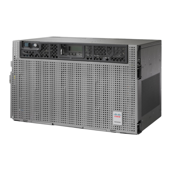
The NCS 2006 is FIPS 140-2 and CC compliant. The NCS 2006 shelf has 8 horizontal card slots numbered 1 to 8. While Slot 2 to Slot 7 house MSTP cards that provide 10 to 100 Gbps interconnections, Slot 1 and Slot 8 accommodate the TNC, TNCE, TSC, or TSCE cards (timing and control cards). -
Page 32: Cisco Ncs 2015 Shelf
The NCS 2006 is mounted on a 19-inch or 23-inch ANSI rack (482.6 or 584.2 mm), or on a 600 x 600-mm (23.6 x 23.6-inch) or 600 x 300-mm (23.6 x 11.8-inch) ETSI standard equipment rack. The rack mounting is done using the mounting brackets or air deflectors. - Page 33 Overview Cisco NCS 2015 Shelf integrated with the fan tray assembly. The following figure shows the front view of the Cisco NCS 2015 DC chassis. Figure 3: Front View of the NCS 2015 DC Chassis Power modules Alarm dry contacts and...
- Page 34 Overview Cisco NCS 2015 Shelf The following figure shows the front view of the Cisco NCS 2015 AC chassis. Figure 4: Front View of the NCS 2015 AC Chassis Power modules Alarm dry contacts and BITS in the power input...
- Page 35 (23.6 x 11.8-inch) ETSI standard equipment rack. The rack is mounted using mounting brackets. When installed in an equipment rack, the Cisco NCS 2015 shelf is typically connected to a fuse and alarm panel to provide centralized alarm connection points and distributed power for the NCS 2015. Fuse and alarm...
-
Page 36: Cisco Ncs 2000 Series Hardware Installation Guide
Install and operate the NCS 2015 only in environments that do not expose wiring or cabling to the outside Note plant. For information on hardware and software specifications for the NCS shelf, see the NCS 2015 Shelf Specifications, on page 473. Cisco NCS 2000 Series Hardware Installation Guide... -
Page 37: Preparing To Install The Cisco Ncs 2002, Ncs 2006, And Ncs 2015 Shelf
C H A P T E R Preparing to Install the Cisco NCS 2002, NCS 2006, and NCS 2015 Shelf This chapter explains how to prepare for the Cisco NCS 2002, NCS 2006, and NCS 2015 shelf install. The sections are: •... -
Page 38: Required Tools And Equipment
To avoid damage during shipment, either a standard front door or a temporary front door is preinstalled in the Cisco NCS 2006 shelves. If a front door is ordered, a standard front door is preinstalled. If a front door is not ordered, a temporary front door is preinstalled. -
Page 39: Cisco Ncs 2000 Series Hardware Installation Guide
Preparing to Install the Cisco NCS 2002, NCS 2006, and NCS 2015 Shelf Cisco Supplied Materials Table 1: Cisco Supplied Materials Required to Install Cisco Supplied Material NCS 2002 NCS 2006 NCS 2015 Brackets ANSIRJ LAN bracket (1) ANSIRJ LAN bracket (1) —... -
Page 40: Cisco Ncs 2000 Series Hardware Installation Guide
Preparing to Install the Cisco NCS 2002, NCS 2006, and NCS 2015 Shelf Cisco Supplied Materials Cisco Supplied Material NCS 2002 NCS 2006 NCS 2015 Power Lug ANSI — Double-hole power lug for DC power connection with a wire Double-hole power lug for DC... -
Page 41: User Supplied Materials
— Anti-oxidant (1) Caution Only use the power cables that are designed to be used with the NCS 2002, NCS 2006, or NCS 2015. These are sold separately. User Supplied Materials The following materials, tools, and equipment are required but are not supplied with the NCS 2002, NCS 2006, and NCS 2015. -
Page 42: Cisco Ncs 2000 Series Hardware Installation Guide
Preparing to Install the Cisco NCS 2002, NCS 2006, and NCS 2015 Shelf User Supplied Materials User Supplied Material NCS 2002 NCS 2006 NCS 2015 Cables ANSI ANSI • Power cable (from fuse • Power cable (from fuse • Power cable (from fuse... -
Page 43: Cisco Ncs 2000 Series Hardware Installation Guide
Preparing to Install the Cisco NCS 2002, NCS 2006, and NCS 2015 Shelf User Supplied Materials User Supplied Material NCS 2002 NCS 2006 NCS 2015 Fuse and Alarm panel ANSI ANSI ANSI Fuse and alarm panel Fuse and alarm panel... -
Page 44: Ordering Solutions For Ncs 2002, Ncs 2006, And Ncs 2015
Wire wrapper Wire wrapper Wire wrapper Ring runs are not provided by Cisco and can hinder side-by-side shelf installation where space is limited. Note Ordering Solutions for NCS 2002, NCS 2006, and NCS 2015 Two ordering solutions for the NCS 2002 shelf are offered. Select one of these solutions: •... -
Page 45: Ncs 2006
NCS 2006 The NCS 2006 shelf assemblies have eight card slots numbered sequentially from bottom to top. Slots 1 and 8 are reserved for control cards (TNC, TNCE, TSC, or TSCE). Slots 2, 3, 4, 5, 6, and 7 are dedicated for common line cards. -
Page 46: Ncs 2015
Slots 2 to 7. New line cards with high-speed backplane connectors. Pink/Pentagon Slots 4 and 5. New Uplink card. When the NCS 2006 shelf is powered at –60 VDC (nominal), only TNC, OPT-AMP-C, OPT-AMP-17-C, Note OPT-EDFA-17, OPT-EDFA-24, and NCS 2006 ECU can be installed. NCS 2015 The NCS 2015 shelf assemblies have 18 card slots numbered sequentially from left to right. -
Page 47: Card Replacement
CTC. For specifics, refer to the “Maintain the Node” chapter in the Cisco NCS 2000 Series Network Configuration Guide . Removing any active card from the shelf can result in traffic interruption. Use caution when replacing Caution cards and verify that only inactive or standby cards are being replaced. -
Page 48: Ntp-L41 Unpacking And Inspecting The Shelf
Preparing to Install the Cisco NCS 2002, NCS 2006, and NCS 2015 Shelf NTP-L41 Unpacking and Inspecting the Shelf An improper removal (IMPROPRMVL) alarm is raised whenever a card pull (reseat) is performed, unless Note the card is deleted in CTC first. The alarm clears after the card replacement is complete. -
Page 49: Cisco Ncs 2000 Series Hardware Installation Guide
DLP-L62 Unpacking and Verifying the Shelf Procedure Step 1 When you receive the NCS 2002, NCS 2006, or NCS 2015 system equipment at the installation site, open the top of the box. The Cisco Systems logo designates the top of the box. Step 2 Remove the foam inserts from the box. -
Page 50: Dlp-L63 Inspecting The Shelf
• The pins are not bent or broken. • The frame is not bent. Step 3 If the pins are bent or broken, or the frame is bent, call your Cisco sales engineer for a replacement. Step 4 Return to your originating procedure (NTP). -
Page 51: Chapter 3 Cisco Ncs 2002 Installation Overview
C H A P T E R Cisco NCS 2002 Installation Overview This chapter provides an overview of the NCS 2002 installation. • Cisco NCS 2002 Installation Overview, page 23 Cisco NCS 2002 Installation Overview This chapter includes these sections: • Mounting the brackets •... -
Page 52: Cisco Ncs 2000 Series Hardware Installation Guide
Cisco NCS 2002 Installation Overview Cisco NCS 2002 Installation Overview Cisco NCS 2000 Series Hardware Installation Guide... -
Page 53: Installing The Air Flow Regulator
• Front to Front— Only ETSI rack • Front to Back— For ANSI and ETSI racks • Front to Top— Only ETSI rack In an ANSI rack, the air deflectors are mounted only on the 23-inch rack configuration. Cisco NCS 2000 Series Hardware Installation Guide... -
Page 54: Air Plenum
The air flow is deflected by 90 degrees and exited out in the rear end. The following figure shows the air flow inside the air plenum. Figure 10: Air flow within the air plenum Cisco NCS 2000 Series Hardware Installation Guide... -
Page 55: Air Plenum Rack And Cabinet Compatibility
The following figures show the dimensions of the air plenum relative to the cabinet or rack. Figure 11: Dimension of Cisco NCS 2002 chassis relative to the air plenum Figure 12: Dimension of Cisco NCS 2002 chassis relative to the air plenum Air Plenum Rack and Cabinet Compatibility The table shows the compatibility of air plenum with the ANSI and ETSI racks and cabinets. -
Page 56: Ntp-L42 Install The Air Plenum In Ncs 2002 Shelf
Figure 13: Minimum rear opening for ANSI 19-inch and ETSI configuration NTP-L42 Install the Air Plenum in NCS 2002 Shelf Purpose This procedure installs the air plenum to orient the air flow in front-to- back direction in the NCS 2002 shelf. Cisco NCS 2000 Series Hardware Installation Guide... -
Page 57: Cisco Ncs 2000 Series Hardware Installation Guide
For nominal voltage of -60 VDC, the input voltage range is from -40 to -72 VDC. Note Use only the fastening hardware provided with the NCS 2002 to prevent loosening, deterioration, and Note electromechanical corrosion of the hardware and joined material. Cisco NCS 2000 Series Hardware Installation Guide... -
Page 58: Dlp-L65 Installing Air Plenum For Ncs 2002 Shelf In Ansi 19-Inch Configuration
• Small slot-head screwdriver • Screws: #12-24 x 0.50 pan-head Phillips screws • Wing head screws (4) • One air plenum kit (horizontal and vertical air plenum) Required/As Needed As needed Onsite/Remote Onsite None Security Level Cisco NCS 2000 Series Hardware Installation Guide... -
Page 59: Cisco Ncs 2000 Series Hardware Installation Guide
Insert the vertical plenum in the free space between the horizontal plenum and cabinet. b) Install t he wing head screws fom the internal side of the horizontal plenum as shown in the following figure. Cisco NCS 2000 Series Hardware Installation Guide... -
Page 60: Cisco Ncs 2000 Series Hardware Installation Guide
Figure 15: Installing the left vertical air plenum Step 4 Install the vertical air plenum to the right of the horizontal air plenum. Follow step 3a to 3c. Figure 16: Installing the right vertical air plenum Cisco NCS 2000 Series Hardware Installation Guide... -
Page 61: Dlp-L69 Installing Air Plenum In Ncs 2002 Shelf For Ansi 23-Inch Configuration
Return to your originating procedure (NTP). DLP-L69 Installing Air Plenum in NCS 2002 Shelf for ANSI 23-inch Configuration Purpose This task installs the air plenum for the NCS 2002 shelf in the ANSI 23-inch cabinet or rack configuration. Cisco NCS 2000 Series Hardware Installation Guide... -
Page 62: Cisco Ncs 2000 Series Hardware Installation Guide
The air plenums for ANSI 23-inch configuration can also be pre-assembled outside the cabinet and then Note installed inside the cabinet. See DLP-L71 Installing Pre-assembled Air Plenums in ANSI 23-inch Configuration, on page 38 Cisco NCS 2000 Series Hardware Installation Guide... -
Page 63: Cisco Ncs 2000 Series Hardware Installation Guide
Align the screws to fix the adapter plates to the shelf. Insert the screws and tighten them to a torque value of 11.5 in-lb (1.3 N-m). Figure 18: Installing the adapter plates on the horizontal air plenum Cisco NCS 2000 Series Hardware Installation Guide... -
Page 64: Cisco Ncs 2000 Series Hardware Installation Guide
Install the wing head screws from the internal side of the horizontal plenum as shown in the following figure. c) Tighten the screws to a torque value of 11.5 in-lb (1.3 N-m). Figure 20: Installing the left vertical air plenum Cisco NCS 2000 Series Hardware Installation Guide... -
Page 65: Cisco Ncs 2000 Series Hardware Installation Guide
19-inch Brackets on the NCS 2002 Shelf for ANSI Rack Configuration, on page Step 8 Install the NCS 2002 empty chassis below the horizontal plenum. Figure 22: Installing the NCS 2002 chassis below the horizontal air plenum Cisco NCS 2000 Series Hardware Installation Guide... -
Page 66: Dlp-L71 Installing Pre-Assembled Air Plenums In Ansi 23-Inch Configuration
• Screws: #12-24 x 3/4 pan-head Phillips mounting screws (8) • Wing head screws (4) • Adapter plates • One air plenum kit (horizontal and vertical air plenum) As needed Required/As Needed Onsite/Remote Onsite Security Level None Cisco NCS 2000 Series Hardware Installation Guide... -
Page 67: Cisco Ncs 2000 Series Hardware Installation Guide
Install the wing head screws from the internal side of the horizontal plenum and tighten the screws to a torque value of 11.5 in-lb (1.3 N-m). Step 5 Install the vertical air plenum to the left of the horizontal air plenum. Follow step 4. Figure 23: Pre-assembling the air plenums Cisco NCS 2000 Series Hardware Installation Guide... -
Page 68: Dlp-L70 Installing Air Plenum For Ncs 2002 Shelf In Etsi Configuration
• Screws: M6.0 x 20 pan-head Phillips screws (4) • Wing head screws (4) • Adapter plates • One air plenum kit (horizontal and vertical air plenum) Required/As Needed As needed Onsite/Remote Onsite Cisco NCS 2000 Series Hardware Installation Guide... -
Page 69: Cisco Ncs 2000 Series Hardware Installation Guide
Align the screws to fix the adapter plates to the horizontal air plenum. Insert the screws and tighten them to a torque value of 11.5 in-lb (1.3 N-m) as shown in the following figure. Figure 25: Installing the adapter plates on the horizontal air plenum Cisco NCS 2000 Series Hardware Installation Guide... -
Page 70: Cisco Ncs 2000 Series Hardware Installation Guide
Install the wing head screws from the internal side of the horizontal plenum as shown in the following figure. c) Tighten the screws to a torque value of 11.5 in-lb (1.3 N-m). Figure 27: Installing the left vertical air plenum Cisco NCS 2000 Series Hardware Installation Guide... -
Page 71: Cisco Ncs 2000 Series Hardware Installation Guide
19-inch Brackets on the NCS 2002 Shelf for ANSI Rack Configuration, on page Step 8 Install the NCS 2002 empty chassis below the horizontal plenum. Figure 29: Installing the NCS 2002 chassis below the horizontal air plenum Step 9 Return to your originating procedure (NTP). Cisco NCS 2000 Series Hardware Installation Guide... -
Page 72: Cisco Ncs 2000 Series Hardware Installation Guide
Installing the Air Flow Regulator DLP-L70 Installing Air Plenum for NCS 2002 Shelf in ETSI Configuration Cisco NCS 2000 Series Hardware Installation Guide... -
Page 73: Mounting The Cisco Ncs 2002 Brackets
20 Required/As Needed As needed Onsite Onsite/Remote Security Level None Perform these procedures as required: • DLP-L35 Mounting the 19-inch Brackets on the NCS 2002 Shelf for ANSI Rack Configuration, on page 46 Cisco NCS 2000 Series Hardware Installation Guide... -
Page 74: Configuration
NCS 2002 ship kit, or remove the coating from the threads to ensure electrical continuity. The mounting brackets can be installed in the front or the middle position of the chassis. Note Cisco NCS 2000 Series Hardware Installation Guide... -
Page 75: Configuration
This task installs the 23-inch mounting brackets on the NCS 2002 shelf for ANSI rack configuration. Tools/Equipment • #2 Phillips Dynamometric screwdriver • Medium slot-head screwdriver • Small slot-head screwdriver Prerequisite Procedures NTP-L41 Unpacking and Inspecting the Shelf, on page Cisco NCS 2000 Series Hardware Installation Guide... -
Page 76: Cisco Ncs 2000 Series Hardware Installation Guide
NCS 2002 ship kit, or remove the coating from the threads to ensure electrical continuity. The mounting brackets can be installed in the front or the middle position of the chassis. Note Cisco NCS 2000 Series Hardware Installation Guide... -
Page 77: For Ansi Rack Configuration
As needed Required/As Needed Onsite/Remote Onsite Security Level None Use only the fastening hardware provided with the NCS 2002 to prevent loosening, deterioration, and Caution electromechanical corrosion of the hardware and joined material. Cisco NCS 2000 Series Hardware Installation Guide... -
Page 78: Cisco Ncs 2000 Series Hardware Installation Guide
Insert the screws and tighten them to a torque value of 11.5 in-lb (1.3 N-m). See Diagram 4 of the following figure. Figure 31: Mounting the Air Deflectors (Front-to-Back) on the NCS 2002 Shelf for ANSI Rack Configuration Cisco NCS 2000 Series Hardware Installation Guide... -
Page 79: Ntp-L45 Mounting The Brackets In Etsi Configuration
NTP-L45 Mounting the Brackets in ETSI Configuration Purpose This task installs the 19-inch mounting brackets to the NCS 2002 shelf for ANSI rack configuration. Tools/Equipment • #2 Phillips Dynamometric screwdriver • Medium slot-head screwdriver • Small slot-head screwdriver Cisco NCS 2000 Series Hardware Installation Guide... -
Page 80: Dlp-L38 Mounting The Brackets On The Ncs 2002 Shelf For Etsi Rack Configuration
Tools/Equipment • #2 Phillips Dynamometric screwdriver • Medium slot-head screwdriver • Small slot-head screwdriver Prerequisite Procedures NTP-L41 Unpacking and Inspecting the Shelf, on page Required/As Needed As needed Onsite Onsite/Remote Security Level None Cisco NCS 2000 Series Hardware Installation Guide... -
Page 81: Cisco Ncs 2000 Series Hardware Installation Guide
Repeat steps 1 through 3 for the mounting bracket on the opposite side. Figure 33: Mounting the Brackets on the NCS 2002 Shelf for ETSI Rack Configuration Step 5 Return to your originating procedure (NTP). Cisco NCS 2000 Series Hardware Installation Guide... -
Page 82: Rack Configuration
If the 100G-LC-C, 10x10G-LC, or CFP-LC cards are to be installed in the NCS 2002 shelf, do not Note mount the left front deflector (exhaust air deflector). Use the standard brackets directly to mount the NCS 2002s shelf. Cisco NCS 2000 Series Hardware Installation Guide... -
Page 83: For Etsi Rack Configuration
DLP-L40 Mounting the Bracket with Air Deflectors (Front-to-Back) on the NCS 2002 Shelf for ETSI Rack Configuration Purpose This task installs the bracket with air deflectors (front-to-back) on the NCS 2002 shelf for ETSI rack configuration. Cisco NCS 2000 Series Hardware Installation Guide... -
Page 84: Cisco Ncs 2000 Series Hardware Installation Guide
If the 100G-LC-C, 10x10G-LC, or CFP-LC cards are to be installed in the NCS 2002 shelf, do not Note mount the left back deflector (exhaust air deflector). Use the standard brackets directly to mount the NCS 2002 shelf. Cisco NCS 2000 Series Hardware Installation Guide... -
Page 85: Cisco Ncs 2000 Series Hardware Installation Guide
Insert the screws and tighten them to a torque value of 11.5 in-lb (1.3 N-m). See Diagram 4 of the following figure. Figure 35: Mounting the Air Deflectors (Front-to-Back) on the NCS 2002 Shelf for ETSI Rack Configuration Cisco NCS 2000 Series Hardware Installation Guide... -
Page 86: Dlp-L41 Mounting The Bracket With Air Deflectors (Front-To-Top) On The Ncs 2002 Shelf For Etsi Rack Configuration
2002 Shelf for ETSI Rack Configuration Purpose This task installs the bracket with air deflectors (front-to-top configuration) on the NCS 2002 shelf. Tools/Equipment • #2 Phillips Dynamometric screwdriver • Medium slot-head screwdriver • Small slot-head screwdriver Cisco NCS 2000 Series Hardware Installation Guide... -
Page 87: Cisco Ncs 2000 Series Hardware Installation Guide
If the 100G-LC-C, 10x10G-LC, or CFP-LC cards are to be installed in the NCS 2002 shelf, do not Note mount the left top deflector (exhaust air deflector). Use the standard brackets directly to mount the NCS 2002 shelf. Cisco NCS 2000 Series Hardware Installation Guide... -
Page 88: Cisco Ncs 2000 Series Hardware Installation Guide
Step 14 Insert the screws and tighten them to a torque value of 11.5 in-lb (1.3 N-m). See Diagram 4 of the following figure. Figure 37: Mounting the Bracket with Air Deflectors (Front-to-Top) on the NCS 2002 Shelf for ETSI Rack Configuration Step 15 Return to your originating procedure (NTP). Cisco NCS 2000 Series Hardware Installation Guide... -
Page 89: Mounting The Cisco Ncs 2002 Shelf
Electronic Industries Alliance (EIA) standard and Telcordia-standard racks. The shelf is a total of 17.2 inches (431.8 mm) wide with no mounting ears attached. Ring runs are not provided by Cisco and might hinder side-by-side installation of shelves where space is limited. -
Page 90: Mounting A Single Node
The figure below shows the dimensions of the NCS 2002 shelf on a 19-inch (482.6 mm) ANSI rack configuration with brackets mounted in the front position. Figure 38: Cisco NCS 2002 Shelf Dimensions for a 19-inch ANSI Rack Configuration Mounting a Single Node Mounting the NCS 2002 shelf on a rack requires a minimum of 3.5 inches (88.9 mm) of vertical rack space. -
Page 91: Cisco Ncs 2000 Series Hardware Installation Guide
1.7 inch (43.18 mm) from the front of the rack and is a total of 431.8 mm (17 inch) wide with no mounting ears attached. Cisco does not provide ring runs, which might hinder side-by-side installation of shelves where space is limited. -
Page 92: Mounting A Single Node
The figure below provides the dimensions of the NCS 2002 shelf installed on a 600 x 600-mm (23.6 x 23.6-inch) ETSI standard equipment rack. Figure 39: Cisco NCS 2002 Shelf Dimensions for an ETSI Rack Configuration Mounting a Single Node The NCS 2002 requires 3.5 inches (88.9 mm) minimum of vertical rack space. -
Page 93: Wall Mounting The Ncs 2002 Shelf
The NCS 2002 shelf can be mounted on the wall using the wall mount brackets. The type of screws used to mount the brackets on the wall depends on the wall-type and are not provided by Cisco. After the NCS 2002 shelf is mounted on the wall, a fire protective tray is installed on the wall mount bracket to support the shelf. -
Page 94: Cisco Ncs 2000 Series Hardware Installation Guide
(25.4 mm). Statement 1076 Note Make sure that the correct type of 19-inch ANSI rack is used for mounting the NCS 2002 shelf. During installation, do not use the door to handle the chassis. Note Cisco NCS 2000 Series Hardware Installation Guide... -
Page 95: Dlp-L42 Mounting The Ncs 2002 Shelf On A Rack (One Person)
DLP-L44 Mounting the NCS 2002 Shelf on the Desktop, on page 72 Step 3 Connect the chassis to the office ground. For detailed instructions on how to ground the chassis, refer to the Electrostatic Discharge and Grounding Guide for Cisco NCS 2000 Series. Step 4... -
Page 96: Step 1
The NCS 2002 requires a minimum of 3.5 inches (88.9 mm) of vertical rack space. To ensure that the Note mounting is secure, use two to three NCS 2006 mounting screws on each side of the shelf. A shelf should be mounted at the bottom of the rack if it is the only unit in the rack. -
Page 97: Dlp-L43 Mounting The Ncs 2002 Shelf On The Wall
DLP-L43 Mounting the NCS 2002 Shelf on the Wall This task explains how to mount the NCS 2002 shelf Purpose on the wall. Tools/Equipment • # 2 Phillips Dynamometric screwdriver • 6 pan-head Phillips mounting screws Cisco NCS 2000 Series Hardware Installation Guide... -
Page 98: Cisco Ncs 2000 Series Hardware Installation Guide
2002 shelf assembly on the wall. The type of screws used to mount the brackets on the wall depends on the wall-type and are not provided by Cisco. The screws used must be able to sustain an overall weight of at least 20 kg (44 lb). -
Page 99: Cisco Ncs 2000 Series Hardware Installation Guide
Step 4 Insert the screws and tighten them to a torque value of 11.5 in-lb (1.3 N-m). See diagram 2 of the figure below. Figure 41: Wall Mounting of the NCS 2002 Shelf Cisco NCS 2000 Series Hardware Installation Guide... -
Page 100: Dlp-L44 Mounting The Ncs 2002 Shelf On The Desktop
DLP-L44 Mounting the NCS 2002 Shelf on the Desktop Purpose This task explains mount the shelf on the desktop. None Tools/Equipment Prerequisite Procedures None Required/As Needed As needed Onsite Onsite/Remote Security Level None Cisco NCS 2000 Series Hardware Installation Guide... -
Page 101: Cisco Ncs 2000 Series Hardware Installation Guide
Figure 43: Desktop Mounting of the NCS 2002 Shelf Step 5 Place the NCS 2002 shelf on a desktop, or other flat and secure surface. Step 6 Return to your originating procedure (NTP). Cisco NCS 2000 Series Hardware Installation Guide... -
Page 102: Cisco Ncs 2000 Series Hardware Installation Guide
Mounting the Cisco NCS 2002 Shelf DLP-L44 Mounting the NCS 2002 Shelf on the Desktop Cisco NCS 2000 Series Hardware Installation Guide... -
Page 103: Connecting Power And Ground
For a DC power supply, the fuse rating must not exceed 15A. The voltages –40.5 VDC and –57.6 VDC are, respectively, the minimum and maximum voltages required to power the chassis. The nominal steady state voltage is -48 VDC. Cisco NCS 2000 Series Hardware Installation Guide... -
Page 104: Etsi Power And Ground
Only use the power cables shipped with the NCS 2002 shelf. NTP-L35 Installing the Power and Ground to the NCS 2002 Shelf This procedure installs power feeds and grounds the Purpose NCS 2002 system. Cisco NCS 2000 Series Hardware Installation Guide... -
Page 105: Cisco Ncs 2000 Series Hardware Installation Guide
2002 ETSI Prerequisite Procedures • Connect the chassis to the office ground. For detailed instructions on how to ground the chassis, refer to the Electrostatic Discharge and Grounding Guide for Cisco NCS 2000 Series Required Required/As Needed Onsite/Remote Onsite Security Level... -
Page 106: Cisco Ncs 2000 Series Hardware Installation Guide
Before working on a chassis or working near power supplies, unplug the power cord on AC units. Statement 246 Warning This equipment is intended to be grounded. Ensure that the host is connected to earth ground during normal use. Statement 39 Use copper conductors only. Statement 1025 Warning Cisco NCS 2000 Series Hardware Installation Guide... -
Page 107: Electrostatic Discharge And Grounding Guide For Cisco Ncs
DLP-L51 Connecting Office Power (DC) to the NCS 2002 Shelf (ETSI Only), on page 88 Step 3 Connect the office ground to the NCS 2002 shelf. For detailed instructions on grounding, refer to the Electrostatic Discharge and Grounding Guide for Cisco NCS 2000 Series Step 4 Complete... -
Page 108: Dlp-L49 Connecting Office Power (Ac) To The Ncs 2002 Shelf
• Connect the chassis to the office ground. For detailed instructions on how to ground the chassis, refer to the Electrostatic Discharge and Grounding Guide for Cisco NCS 2000 Series • NTP-L30 Opening and Removing the Standard Door of the NCS 2002 Shelf, on page 111... -
Page 109: Cisco Ncs 2000 Series Hardware Installation Guide
If the system loses power or if both TNC, TNCE, TSC, or TSCE cards are reset, you must reset the NCS Note 2002 clock. After powering down, the date defaults to January 1, 1970, 00:04:15. To reset the clock, see NTP-G24 Set Up Name, Date, Time, and Contact Information Cisco NCS 2000 Series Hardware Installation Guide... -
Page 110: Cisco Ncs 2000 Series Hardware Installation Guide
Connect the power cable to the fuse panel or power source. Note The voltage rating value for AC power ranges between 100 VAC to 240 VAC depending on the standards in various countries. Cisco NCS 2000 Series Hardware Installation Guide... -
Page 111: Dlp-L50 Connecting Office Power (Dc) To The Ncs 2002 Shelf (Ansi Only)
AC power cable for data center right exit 15454-M-ACL6-R= DLP-L50 Connecting Office Power (DC) to the NCS 2002 Shelf (ANSI Only) Purpose This task connects DC power to the NCS 2002 shelf (ANSI Only). Cisco NCS 2000 Series Hardware Installation Guide... -
Page 112: Cisco Ncs 2000 Series Hardware Installation Guide
• Connect the chassis to the office ground. For detailed instructions on how to ground the chassis, refer to the Electrostatic Discharge and Grounding Guide for Cisco NCS 2000 Series • NTP-L30 Opening and Removing the Standard Door of the NCS 2002 Shelf, on page 111... -
Page 113: Cisco Ncs 2000 Series Hardware Installation Guide
NTP-G24 Set Up Name, Date, Time, and Contact Information . If you are using the TNC, TNCE, TSC, or TSCE cards, the system clock will run for up to three hours. In this case, no action would be required. Cisco NCS 2000 Series Hardware Installation Guide... -
Page 114: Cisco Ncs 2000 Series Hardware Installation Guide
Verify that the DC power module is installed in Slot A. Step 8 Remove the screws from the terminal block protective cover from the DC power module (see the figure below). Figure 46: Connecting Office Power — DC Power Module (ANSI Only) Cisco NCS 2000 Series Hardware Installation Guide... -
Page 115: Cisco Ncs 2000 Series Hardware Installation Guide
Step 10 Tighten the screws to a torque value of 7 in-lb (0.79 N-m) to lock the lugs. Step 11 Tighten the screws to a torque value of 4 in-lb (0.45 N-m) of the terminal block protective cover on the DC power module (see the figure below). Cisco NCS 2000 Series Hardware Installation Guide... -
Page 116: Dlp-L51 Connecting Office Power (Dc) To The Ncs 2002 Shelf (Etsi Only)
(push-in) connectors, quick-connect, or other friction-fit connectors. Step 12 Return to your originating procedure (NTP). DLP-L51 Connecting Office Power (DC) to the NCS 2002 Shelf (ETSI Only) Purpose This task connects power to the NCS 2002 shelf (ETSI Only). Cisco NCS 2000 Series Hardware Installation Guide... -
Page 117: Cisco Ncs 2000 Series Hardware Installation Guide
• Connect the chassis to the office ground. For detailed instructions on how to ground the chassis, refer to the Electrostatic Discharge and Grounding Guide for Cisco NCS 2000 Series • NTP-L30 Opening and Removing the Standard Door of the NCS 2002 Shelf, on page 111... -
Page 118: Cisco Ncs 2000 Series Hardware Installation Guide
Connect the return cables of the power supply to the Earth ground located at the power supply side. Step 2 Verify that the DC power module is installed in Slot A of the NCS 2002. Figure 49: Connecting Office Power — DC Power Module (ETSI Only) Cisco NCS 2000 Series Hardware Installation Guide... -
Page 119: Dlp-L52 Turning On And Verifying Ac Office Power On The Ncs 2002 Shelf
Return to your originating procedure (NTP). DLP-L52 Turning On and Verifying AC Office Power on the NCS 2002 Shelf Purpose This task measures the power to verify correct power and returns for the NCS 2002 shelf. Tools/Equipment Voltmeter Cisco NCS 2000 Series Hardware Installation Guide... -
Page 120: Dlp-L53 Turning On And Verifying Dc Office Power On The Ncs2002Shelf
• Connect the chassis to the office ground. For detailed instructions on how to ground the chassis, refer to the Electrostatic Discharge and Grounding Guide for Cisco NCS 2000 Series • NTP-L30 Opening and Removing the Standard Door of the NCS 2002 Shelf, on page 111 •... -
Page 121: Cisco Ncs 2000 Series Hardware Installation Guide
• Connect the chassis to the office ground. For detailed instructions on how to ground the chassis, refer to the Electrostatic Discharge and Grounding Guide for Cisco NCS 2000 Series • NTP-L30 Opening and Removing the Standard Door of the NCS 2002 Shelf, on page 111 •... -
Page 122: Cisco Ncs 2000 Series Hardware Installation Guide
–57.6 VDC. Then place the red test lead of the voltmeter to the RET2 (B-side return ground) black cable and verify that no voltage is present. Step 4 Return to your originating procedure (NTP). Cisco NCS 2000 Series Hardware Installation Guide... -
Page 123: Connecting And Routing The Cables And Wires
Always use the supplied Electrostatic Discharge (ESD) wristband when working with a powered NCS Caution 2002. For detailed instructions on how to wear the ESD wristband, refer to the Electrostatic Discharge and Grounding Guide for Cisco NCS 2000 Series Cisco NCS 2000 Series Hardware Installation Guide... -
Page 124: Dlp-L54 Installing Timing Wires In Cisco Ncs 2002 - Ansi
This is the minimum distance required to place the bulk attenuator outside the shelf from any port of a card. Procedure Step 1 Complete either DLP-L54 Installing Timing Wires in Cisco NCS 2002 - ANSI, on page 96or DLP-L55 Installing Timing Wires in Cisco NCS 2002- ETSI, on page 98 if you are provisioning external timing. -
Page 125: Cisco Ncs 2000 Series Hardware Installation Guide
Connecting and Routing the Cables and Wires DLP-L54 Installing Timing Wires in Cisco NCS 2002 - ANSI Procedure Step 1 Locate the timing BITS connectors in the DC-2 or AC-2 Power Module, as shown in the figures below . Figure 51: DC-2 Power Module ANSI BITS connectors... -
Page 126: Dlp-L55 Installing Timing Wires In Cisco Ncs 2002- Etsi
Connecting and Routing the Cables and Wires DLP-L55 Installing Timing Wires in Cisco NCS 2002- ETSI Step 2 Connect the wire wrap cable to the appropriate timing connector in the Power Module. Step 3 Connect the other end of the cable to the external source of the timing. -
Page 127: Cisco Ncs 2000 Series Hardware Installation Guide
Connecting and Routing the Cables and Wires DLP-L55 Installing Timing Wires in Cisco NCS 2002- ETSI Tools/Equipment 75-ohm coaxial cable with a DIN 1.0/2.3 miniature coax connector. The PID for the BITS IN/OUT cable is 15454-M-TMGCBL=. Prerequisite Procedures None Required/As Needed... -
Page 128: Cisco Ncs 2000 Series Hardware Installation Guide
Connecting and Routing the Cables and Wires DLP-L55 Installing Timing Wires in Cisco NCS 2002- ETSI Procedure Step 1 Locate the timing BITS connectors in the DC-2E or AC-2 Power Module, as shown in the figures below. Figure 53: DC-2E Power Module ETSI BITS Connectors... -
Page 129: Cisco Ncs 2000 Series Hardware Installation Guide
Connecting and Routing the Cables and Wires DLP-L55 Installing Timing Wires in Cisco NCS 2002- ETSI Step 2 Using a coaxial cable with DIN 1.0/2.3 miniature coax connectors, connect the clock cable to the appropriate connector in the Power Module. -
Page 130: Dlp-L56 Installing Lan Wires In Cisco Ncs 2002
Connecting and Routing the Cables and Wires DLP-L56 Installing LAN Wires in Cisco NCS 2002 DLP-L56 Installing LAN Wires in Cisco NCS 2002 This task installs the LAN wires in NCS 2002. Purpose Tools/Equipment Standard CAT-5 Ethernet cable straight-through for... -
Page 131: Cisco Ncs 2002 Shelf Installation Acceptance Test
C H A P T E R Cisco NCS 2002 Shelf Installation Acceptance Test This chapter describes how to perform a shelf acceptance test on Cisco NCS 2002 shelf. • NTP-L38 Performing the NCS 2002 Shelf Installation Acceptance Test , page 103... -
Page 132: Dlp-L60 Inspecting The Ncs 2002 Shelf Installation And Connections
Cisco NCS 2002 Shelf Installation Acceptance Test DLP-L60 Inspecting the NCS 2002 Shelf Installation and Connections Table 8: NCS 2002 Shelf Installation Task Summary Description Completed NTP-L41 Unpacking and Inspecting the Shelf, on page 20 Connect the chassis to the office ground. For detailed... -
Page 133: Dlp-L61 Measuring Dc Voltage On The Ncs 2002 Shelf
Cisco NCS 2002 Shelf Installation Acceptance Test DLP-L61 Measuring DC Voltage on the NCS 2002 Shelf Onsite/Remote Onsite Security Level None Procedure Step 1 Make sure all external wiring connections (that is, power, ground, alarms, and so on) are secure. If a wire or cable is loose, return to the appropriate procedure in this chapter to correct it. -
Page 134: Cisco Ncs 2000 Series Hardware Installation Guide
Cisco NCS 2002 Shelf Installation Acceptance Test DLP-L61 Measuring DC Voltage on the NCS 2002 Shelf a) Place the black lead (positive) on the frame ground on the bay. Hold it there while completing substep b. b) Place the red lead (negative) on the fuse power points on the third-party power distribution panel to verify that they read between –40.5 VDC and –57.6 VDC (power) and 0 (return ground). -
Page 135: Front Door
C H A P T E R Installing the Cisco NCS 2002 Door and Other Modules This chapter describes how to install the NCS 2015 door and other modules. The sections are: • Front Door, page 107 • NTP-L29 Installing the Standard Door of the NCS 2002 Shelf, page 108 •... -
Page 136: Ntp-L29 Installing The Standard Door Of The Ncs 2002 Shelf
Installing the Cisco NCS 2002 Door and Other Modules NTP-L29 Installing the Standard Door of the NCS 2002 Shelf An erasable label is pasted on the inside of the front door. You can use the label to record slot and port assignments, card types, node ID, rack ID, and serial number of the NCS 2002 shelf. -
Page 137: Cisco Ncs 2000 Series Hardware Installation Guide
Installing the Cisco NCS 2002 Door and Other Modules NTP-L29 Installing the Standard Door of the NCS 2002 Shelf Onsite/Remote Onsite Security Level None Procedure Step 1 Pull the hinge pins on the standard door in the opposite directions (see the figure below). -
Page 138: Cisco Ncs 2000 Series Hardware Installation Guide
Installing the Cisco NCS 2002 Door and Other Modules NTP-L29 Installing the Standard Door of the NCS 2002 Shelf Step 4 Place the ground strap cable (see the figure below) on the door and the chassis and tighten the nuts. -
Page 139: Ntp-L30 Opening And Removing The Standard Door Of The Ncs 2002 Shelf
Installing the Cisco NCS 2002 Door and Other Modules NTP-L30 Opening and Removing the Standard Door of the NCS 2002 Shelf NTP-L30 Opening and Removing the Standard Door of the NCS 2002 Shelf Purpose This procedure opens and removes the standard door of the NCS 2002. -
Page 140: Cisco Ncs 2000 Series Hardware Installation Guide
Installing the Cisco NCS 2002 Door and Other Modules DLP-L45 Opening the Standard Door of the NCS 2002 Shelf Prerequisite Procedures • NTP-L29 Installing the Standard Door of the NCS 2002 Shelf, on page 108. • Connect the chassis to the office ground. For... -
Page 141: Dlp-L46 Removing The Standard Door Of The Ncs 2002 Shelf
Installing the Cisco NCS 2002 Door and Other Modules DLP-L46 Removing the Standard Door of the NCS 2002 Shelf Step 3 Swing the door open (see the figure below). Figure 61: Cisco NCS 2002 Standard Door — Opened Step 4 Return to your originating procedure (NTP). -
Page 142: Cisco Ncs 2000 Series Hardware Installation Guide
Installing the Cisco NCS 2002 Door and Other Modules DLP-L46 Removing the Standard Door of the NCS 2002 Shelf Procedure Step 1 Unscrew the nut holding the ground cable to the shelf. Remove the nut. Step 2 Remove the ground cable from the shelf (see the figure below). -
Page 143: Ntp-L40 Installing The Deep-Front Panel Of The Ncs 2002 Shelf
Installing the Cisco NCS 2002 Door and Other Modules NTP-L40 Installing the Deep-Front Panel of the NCS 2002 Shelf Step 3 Pull the hinge pins holding the door to the chassis, in the opposite direction (see the figure below). Step 4 Remove the door from its hinges (see the figure below). -
Page 144: Cisco Ncs 2000 Series Hardware Installation Guide
Installing the Cisco NCS 2002 Door and Other Modules NTP-L40 Installing the Deep-Front Panel of the NCS 2002 Shelf Prerequisite Procedures • Connect the chassis to the office ground. For detailed instructions on how to ground the chassis, refer to the... -
Page 145: Cisco Ncs 2000 Series Hardware Installation Guide
Installing the Cisco NCS 2002 Door and Other Modules NTP-L40 Installing the Deep-Front Panel of the NCS 2002 Shelf c) Route the other end of the ground strap cable outside the shelf at an angle of 180 degrees towards the left direction. -
Page 146: Cisco Ncs 2000 Series Hardware Installation Guide
Installing the Cisco NCS 2002 Door and Other Modules NTP-L40 Installing the Deep-Front Panel of the NCS 2002 Shelf Step 3 Place the deep-front panel close to the shelf so that the shelf notches and the deep-front panel retention features are in line (see the figure below). -
Page 147: Cisco Ncs 2000 Series Hardware Installation Guide
Installing the Cisco NCS 2002 Door and Other Modules NTP-L40 Installing the Deep-Front Panel of the NCS 2002 Shelf b) Align the deep-front panel pins present at the bottom of the panel with the shelf hinges (see the figure below). -
Page 148: Cisco Ncs 2000 Series Hardware Installation Guide
Installing the Cisco NCS 2002 Door and Other Modules NTP-L40 Installing the Deep-Front Panel of the NCS 2002 Shelf Step 5 Slide the deep-front panel screws inwards using the plastic tabs to engage the retention features and the pins with the shelf notches and hinges (see the figure below). Verify the engagement by gently applying the pressure to the panel outwards. -
Page 149: Ntp-G331 Removing The Deep-Front Panel Of The Ncs 2002 Shelf
Installing the Cisco NCS 2002 Door and Other Modules NTP-G331 Removing the Deep-Front Panel of the NCS 2002 Shelf Stop. You have completed this procedure. NTP-G331 Removing the Deep-Front Panel of the NCS 2002 Shelf Purpose This procedure removes the deep-front panel of the NCS 2002 system. -
Page 150: Cisco Ncs 2000 Series Hardware Installation Guide
Installing the Cisco NCS 2002 Door and Other Modules NTP-G331 Removing the Deep-Front Panel of the NCS 2002 Shelf Procedure Step 1 Remove the end of the ground strap cable that is connected to the exterior of the deep-front panel (see the figure below). -
Page 151: Cisco Ncs 2000 Series Hardware Installation Guide
Installing the Cisco NCS 2002 Door and Other Modules NTP-G331 Removing the Deep-Front Panel of the NCS 2002 Shelf Step 2 Loosen the panel screws to open the deep-front panel. Step 3 Move the deep-front panel screws in the direction as shown in the figure below to disengage the retention features and the pins from the shelf notches and hinges. -
Page 152: Power Modules
• Timing Connections—The BITS-IN port receives input from third party external sources called SSU (Synchronization Supply Unit) to synchronize the timing of the NCS 2002 shelf. The BITS-OUT port provides output to external devices (other Cisco or third party shelves) to synchronize the timing signals with the NCS 2006 shelf. -
Page 153: Ac Power Module
Installing the Cisco NCS 2002 Door and Other Modules AC Power Module The NCS 2002 shelf has a BITS-IN and BITS-OUT port on the power module. The BITS-IN and BITS-OUT connections are supported by: • ◦ Wire-wrap pins and mini-BNC connectors on the AC power module. -
Page 154: Ntp-L33 Installing The Power Module In The Ncs 2002 Shelf
Installing the Cisco NCS 2002 Door and Other Modules NTP-L33 Installing the Power Module in the NCS 2002 Shelf • One USB port to support passive unit remote inventory connection • Two BITS connections (IN and OUT) for network synchronization that is supported by mini BNC Each ANSI DC power module has: •... -
Page 155: Dlp-L47 Installing The Ac Power Module In The Ncs 2002 Shelf
Installing the Cisco NCS 2002 Door and Other Modules DLP-L47 Installing the AC Power Module in the NCS 2002 Shelf Procedure Step 1 Complete the necessary task as applicable: • DLP-L47 Installing the AC Power Module in the NCS 2002 Shelf, on page 127 •... -
Page 156: Cisco Ncs 2000 Series Hardware Installation Guide
Installing the Cisco NCS 2002 Door and Other Modules DLP-L47 Installing the AC Power Module in the NCS 2002 Shelf Procedure Step 1 Insert the AC power module in Slot A. Figure 75: Installing the AC Power Module Cisco NCS 2000 Series Hardware Installation Guide... -
Page 157: Dlp-L48 Installing The Dc Power Module In The Ncs 2002 Shelf
Installing the Cisco NCS 2002 Door and Other Modules DLP-L48 Installing the DC Power Module in the NCS 2002 Shelf Step 2 Plug the AC power module completely into the chassis. Step 3 Tighten the screw to a torque value of 4 in-lb (0.45 N-m) to lock the power module in the chassis (see the figure below). -
Page 158: Cisco Ncs 2000 Series Hardware Installation Guide
Installing the Cisco NCS 2002 Door and Other Modules DLP-L48 Installing the DC Power Module in the NCS 2002 Shelf Procedure Step 1 Insert the DC power module in Slot A (see the figure below). Figure 77: Installing the DC Power Module Step 2 Plug the DC power module completely into the chassis. -
Page 159: Fan-Tray Assembly
After you install the fan-tray, you should only access it if a fan failure occurs. To clean and replace the fan-tray assembly, see the “Maintain the Node” chapter in the Cisco NCS 2000 Series Network Configuration Guide If the fan-tray assembly is removed from the shelf, wait for at least 5 seconds before plugging it back into Note the shelf. -
Page 160: Fan Failure
Note Error messages appear on the TNC, TNCE, TSC, or TSCE card, the fan-tray LED, and in the Cisco Transport Controller (CTC) when the fan-tray module is removed from the shelf or when one fan is not working. -
Page 161: Cisco Ncs 2000 Series Hardware Installation Guide
Installing the Cisco NCS 2002 Door and Other Modules NTP-L35 Installing the Fan-Tray Assembly in the NCS 2002 Shelf During the system startup or fan-tray replacement, the inventory data of the fan-tray assembly and the Note power module is displayed in the Inventory tab of CTC after a delay of approximately 6 minutes. -
Page 162: Cisco Ncs 2000 Series Hardware Installation Guide
Installing the Cisco NCS 2002 Door and Other Modules NTP-L35 Installing the Fan-Tray Assembly in the NCS 2002 Shelf Step 2 Push the fan-tray assembly such that the backplane connector is completely engaged (see the figure below). Figure 80: Inserting the Fan-Tray Assembly in the NCS 2002 Chassis Step 3 Tighten the screw to a torque value of 4 in-lb (0.45 N-m) to lock the unit (see the figure below). -
Page 163: Air Filter
Installing the Cisco NCS 2002 Door and Other Modules Air Filter Air Filter The NCS 2002 contains a preinstalled disposable air filter (NCS2002-FTF) on the right side of the shelf. The disposable filter is made up of a gray, open-cell, polyurethane foam that is specially coated to provide fire and fungi resistance. -
Page 164: Cisco Ncs 2000 Series Hardware Installation Guide
Installing the Cisco NCS 2002 Door and Other Modules Air Filter Cisco NCS 2000 Series Hardware Installation Guide... -
Page 165: Chapter 1 1 Ncs 2006 Installation Overview
C H A P T E R NCS 2006 Installation Overview This chapter provides an overview of NCS 2006 installation and contains the following section: • NCS 2006 Installation Overview, page 137 NCS 2006 Installation Overview This chapter includes these sections: •... -
Page 166: Cisco Ncs 2000 Series Hardware Installation Guide
NCS 2006 Installation Overview NCS 2006 Installation Overview Cisco NCS 2000 Series Hardware Installation Guide... -
Page 167: Installing The Air Flow Regulator
Air Flow Performance of NCS 2006, page 161 Air Deflector An air deflector is a sheet-metal part that is mounted on the NCS 2006 shelf to orient the air flow in a specific direction. The air deflectors can be mounted in different positions to control the air flow: •... -
Page 168: Air Plenum
4 requirement. NCS 2006 air plenum kit has two horizontal and two vertical air plenums. The air that flows from the front top inlet and the front bottom inlet are channelized to the right vertical plenum, inside the equipment, and then to the exhaust air channel towards the left vertical air plenum. -
Page 169: Cisco Ncs 2000 Series Hardware Installation Guide
Installing the Air Flow Regulator Air Plenum The following figure shows the air flow inside the air plenum. Figure 82: Air flow within the air plenum Cisco NCS 2000 Series Hardware Installation Guide... -
Page 170: Cisco Ncs 2000 Series Hardware Installation Guide
The following figures display the dimensions of the air plenum relative to the cabinet or rack. Figure 83: Dimension of Cisco NCS 2006 chassis relative to the air plenum Figure 84: Dimension on Cisco NCS 2006 relative to the air plenum... -
Page 171: Air Plenum Rack And Cabinet Compatibility
Note The ANSI 19-inch two post rack that is compatible with air plenum installation is available from Telect, with part number 12545-301. Figure 85: Minimum rear opening for ANSI 19-inch and ETSI configuration Cisco NCS 2000 Series Hardware Installation Guide... -
Page 172: Ntp-L43 Install The Air Plenum In Ncs 2006 Shelf
NTP-L43 Install the Air Plenum in NCS 2006 Shelf NTP-L43 Install the Air Plenum in NCS 2006 Shelf Purpose This procedure installs the air plenum to orient the air flow in front-to- back direction in the NCS 2006 shelf. Tools/Equipment • #2 Phillips Dynamometric screwdriver •... -
Page 173: Dlp-L64 Installing Air Plenum For Ncs 2006 Shelf In Ansi 19-Inch Cabinet
For nominal voltage of -60 VDC, the input voltage range is from -40 to -72 VDC. Note Use only the fastening hardware provided with the NCS 2006 to prevent loosening, deterioration, and Note electromechanical corrosion of the hardware and joined material. -
Page 174: Cisco Ncs 2000 Series Hardware Installation Guide
Installing the Air Flow Regulator DLP-L64 Installing Air Plenum for NCS 2006 Shelf in ANSI 19-inch Cabinet Required/As Needed As needed Onsite/Remote Onsite None Security Level Note In the ANSI 19-inch rack or cabinet, the air plenum can be mounted only if the minimum opening is 20.600 inches to install the vertical air plenums behind the front rails. -
Page 175: Cisco Ncs 2000 Series Hardware Installation Guide
Installing the Air Flow Regulator DLP-L64 Installing Air Plenum for NCS 2006 Shelf in ANSI 19-inch Cabinet c) Tighten the screws to a torque value of 11.5 in-lb (1.3 N-m). Figure 87: Installing the left vertical air plenum Step 4 Place the vertical air plenum to the right of the horizontal air plenum. -
Page 176: Cisco Ncs 2000 Series Hardware Installation Guide
Installing the Air Flow Regulator DLP-L64 Installing Air Plenum for NCS 2006 Shelf in ANSI 19-inch Cabinet Step 6 Install the horizontal air plenum above the vertical plenums. Follow step 3a to step 3c. Figure 89: Installing the horizontal air plenum above the vertical plenums... -
Page 177: Dlp-L66 Installing Air Plenum In Ncs 2006 Shelf For Ansi 23-Inch Configuration
Step 7 Install the 19-inch standard brackets on both sides of the chassis in the front position. See DLP-L3 Mounting the Reversible Brackets on the NCS 2006 Shelf for ANSI Rack Configuration, on page 169. Step 8 Check the length between the top and bottom horizontal air plenums where the chassis will be installed. The length must be not less than 10.5 inches (267 mm). -
Page 178: Cisco Ncs 2000 Series Hardware Installation Guide
Installing the Air Flow Regulator DLP-L66 Installing Air Plenum in NCS 2006 Shelf for ANSI 23-inch Configuration Tools/Equipment • #2 Phillips Dynamometric screwdriver • Medium slot-head screwdriver • Small slot-head screwdriver • Screws: #12-24 x 3/4 pan-head Phillips mounting screws (8) •... -
Page 179: Cisco Ncs 2000 Series Hardware Installation Guide
Installing the Air Flow Regulator DLP-L66 Installing Air Plenum in NCS 2006 Shelf for ANSI 23-inch Configuration Procedure Step 1 Install the ANSI 23-inch adapter plates on the horizontal air plenum. Step 2 Align the screws to fix the adapter plates to the shelf. Insert the screws and tighten them to a torque value of 11.5 in-lb (1.3 N-m). -
Page 180: Cisco Ncs 2000 Series Hardware Installation Guide
Installing the Air Flow Regulator DLP-L66 Installing Air Plenum in NCS 2006 Shelf for ANSI 23-inch Configuration b) Install the wing head screws from the internal side of the horizontal plenum as shown in the figure below. c) Tighten the screws to a torque value of 11.5 in-lb (1.3 N-m). -
Page 181: Cisco Ncs 2000 Series Hardware Installation Guide
Installing the Air Flow Regulator DLP-L66 Installing Air Plenum in NCS 2006 Shelf for ANSI 23-inch Configuration Step 7 Place the horizontal air plenum above the shelf slot in the ANSI 23-inch cabinet or rack. Step 8 Install the wing head screws provided with the kit, and tighten to a torque value of 11.5 in-lb (1.3 N-m). -
Page 182: Dlp-L68 Installing Pre-Assembled Air Plenums In Ansi 23-Inch Configuration
Install ANSI 23-inch standard brackets on both sides of the chassis in front position. See DLP-L3 Mounting the Reversible Brackets on the NCS 2006 Shelf for ANSI Rack Configuration, on page 169. Step 10 Check the length between the top and bottom horizontal air plenums where the chassis will be installed. The length must be not less than 10.5 inches (267 mm). -
Page 183: Cisco Ncs 2000 Series Hardware Installation Guide
• Screws: #12-24 x 3/4 pan-head Phillips mounting screws (8) • Wing head screws (8) • Adapter plates • One air plenum kit (horizontal and vertical air plenum) Required/As Needed As needed Onsite Onsite/Remote Security Level None Cisco NCS 2000 Series Hardware Installation Guide... -
Page 184: Cisco Ncs 2000 Series Hardware Installation Guide
Install the vertical air plenum to the right of the horizontal air plenum. Follow step 5. Step 7 Install the horizontal air plenum above the vertical air plenums. Follow step 5. Figure 97: Pre-assembling the air plenums Step 8 Install the pre-assembled air plenum for ANSI 23-inch configuration. Cisco NCS 2000 Series Hardware Installation Guide... -
Page 185: Dlp-L67 Installing Air Plenum For Ncs 2006 Shelf In Etsi Configuration
10.5 inches (267 mm). If the length is less, adjust the position of the top horizontal plenum. Step 11 Install the empty NCS 2006 chassis between the horizontal plenums. Step 12 Return to your originating procedure (NTP). -
Page 186: Cisco Ncs 2000 Series Hardware Installation Guide
Installing the Air Flow Regulator DLP-L67 Installing Air Plenum for NCS 2006 Shelf in ETSI Configuration Tools/Equipment • #2 Phillips Dynamometric screwdriver • Medium slot-head screwdriver • Small slot-head screwdriver • Screws: M6.0 x 20 pan-head Phillips screws (8) • Wing head screws (8) •... -
Page 187: Cisco Ncs 2000 Series Hardware Installation Guide
Installing the Air Flow Regulator DLP-L67 Installing Air Plenum for NCS 2006 Shelf in ETSI Configuration Step 3 Place the horizontal plenum below the chassis slot in the ETSI cabinet. Step 4 Install the wing head screws provided with the kit, and tighten to a torque value of 11.5 in-lb (1.3 N-m). -
Page 188: Cisco Ncs 2000 Series Hardware Installation Guide
Installing the Air Flow Regulator DLP-L67 Installing Air Plenum for NCS 2006 Shelf in ETSI Configuration Step 6 Install the vertical air plenum to the right of the horizontal air plenum. Follow step 5a to step 5c. Step 7 Place the horizontal plenum above the chassis slot in the ETSI cabinet. -
Page 189: Air Flow Performance Of Ncs 2006
10.5 inches (267 mm). If the length is less, adjust the position of the top horizontal plenum. Step 11 Install the NCS 2006 empty chassis between the horizontal plenums. Figure 102: Installing the NCS 2006 chassis below the horizontal air plenum Step 12 Return to your originating procedure (NTP). -
Page 190: Cisco Ncs 2000 Series Hardware Installation Guide
Installing the Air Flow Regulator Air Flow Performance of NCS 2006 Case Deflector Worst Line Card Worst Controller Configuration Slot (#7) Flow, Card Slot (#8) Flow, CFM ETSI Front to Only Inlet 12.2 16.8 12.7 18.4 Side ANSI Front to Inlet and Outlet 13.4... -
Page 191: C H A P T E
Caution and electromechanical corrosion of the hardware and joined material. When mounting the NCS 2006 shelf in a frame with a nonconductive coating (such as paint, lacquer, or Caution enamel) either use the thread-forming screws provided with the NCS 2006 shipping kit, or remove the coating from the threads to ensure electrical continuity. -
Page 192: Cisco Ncs 2000 Series Hardware Installation Guide
Mounting the Brackets on NCS 2006 Shelf NTP-L2 Mounting the Brackets in ANSI Configuration Tools/Equipment • #2 Phillips Dynamometric screwdriver • Medium slot-head screwdriver • Small slot-head screwdriver • ETSI only: ◦ Six M6 x 20 pan-head Phillips mounting screws •... -
Page 193: Cisco Ncs 2000 Series Hardware Installation Guide
Mounting the Brackets on NCS 2006 Shelf NTP-L2 Mounting the Brackets in ANSI Configuration To prevent the system from overheating, do not operate it in an area that exceeds the maximum Warning recommended ambient temperature of: 131°F (55°C). Statement 1047 Take care when connecting units to the supply circuit so that wiring is not overloaded. -
Page 194: Cisco Ncs 2000 Series Hardware Installation Guide
Mounting the Brackets on NCS 2006 Shelf NTP-L2 Mounting the Brackets in ANSI Configuration Remove the door from the NCS 2006 shelf and reinstall it after installing all the other modules. Note Figure 103: Handling the Chassis During Installation Procedure... -
Page 195: Dlp-L1 Verify The Ncs 2006 Shelf For Ac Power Module Installation
Verify the position of the mechanical locking system on the rear side of the chassis. To use the AC power module, the screw must be close to the AC silk-screen text (see the figure below). Figure 104: AC Power Module Installation — Rear Side of the NCS 2006 Shelf Step 2 Loosen the screw and move it to the left position (towards the AC silk-screen text). -
Page 196: Dlp-L2 Verify The Ncs 2006 Shelf For Dc Power Module Installation
Verify the position of the mechanical locking system on the rear side of the chassis. To use the DC power module the screw must be close to the DC silk-screen text (see the figure below). Figure 105: DC Power Module Installation — Rear Side of the NCS 2006 Shelf Cisco NCS 2000 Series Hardware Installation Guide... -
Page 197: Configuration
Caution When mounting the NCS 2006 in a frame with a nonconductive coating (such as paint, lacquer, or enamel) either use the thread-forming screws provided with the NCS 2006 ship kit, or remove the coating from the threads to ensure electrical continuity. -
Page 198: Cisco Ncs 2000 Series Hardware Installation Guide
(see the figure below). The narrow side of the mounting bracket should be towards the front of the shelf. Figure 106: Mounting the Brackets on the NCS 2006 shelf for a 19-inch (482.6-mm) ANSI Configuration Cisco NCS 2000 Series Hardware Installation Guide... -
Page 199: Ansi Rack Configuration
Mounting the Brackets on NCS 2006 Shelf DLP-L4 Mounting the Bracket with Air Deflectors (Front-to-Back) on the NCS 2006 Shelf for ANSI Rack Configuration • For a 23-inch (584.2-mm) configuration, place the narrow side of the mounting bracket flush against the shelf (see the figure below). -
Page 200: Cisco Ncs 2000 Series Hardware Installation Guide
Step 4 Place the left back air deflector flush chassis as shown in Diagram 2 of the figure below. Do not mount the left back deflector (exhaust air deflector), if these cards are to be installed in the NCS 2006 shelf: •... -
Page 201: Cisco Ncs 2000 Series Hardware Installation Guide
Mounting the Brackets on NCS 2006 Shelf DLP-L4 Mounting the Bracket with Air Deflectors (Front-to-Back) on the NCS 2006 Shelf for ANSI Rack Configuration Use the standard brackets directly to mount the NCS 2006 shelf. Figure 108: Mounting the Air Deflectors (Front-to-Back) on the NCS 2006 Shelf for the ANSI rack Configuration... -
Page 202: Ntp-L46 Mounting The Brackets In Etsi Configuration
Step 12 Insert the screws and tighten them to a torque value of 11.5 in-lb (1.3 N-m). Figure 109: Mounting the Brackets with Air Deflectors (Front-to-Back) on the NCS 2006 Shelf for ANSI Rack Configuration Step 13 Return to your originating procedure (NTP). -
Page 203: Cisco Ncs 2000 Series Hardware Installation Guide
Procedure Complete the necessary task as applicable: • DLP-L5 Mounting the Brackets on the NCS 2006 Shelf for ETSI Rack Configuration, on page 176 • DLP-L6 Mounting the Air Deflectors (Front-to-Front) on the NCS 2006 Shelf for ETSI Rack Configuration, on page 177 •... -
Page 204: Dlp-L5 Mounting The Brackets On The Ncs 2006 Shelf For Etsi Rack Configuration
Caution electromechanical corrosion of the hardware and joined material. When mounting the NCS 2006 in a frame with a nonconductive coating (such as paint, lacquer, or enamel) Caution either use the thread-forming screws provided with the NCS 2006 ship kit, or remove the coating from the threads to ensure electrical continuity. -
Page 205: Dlp-L6 Mounting The Air Deflectors (Front-To-Front) On The Ncs 2006 Shelf For Etsi Rack Configuration
Mounting the Brackets on NCS 2006 Shelf DLP-L6 Mounting the Air Deflectors (Front-to-Front) on the NCS 2006 Shelf for ETSI Rack Configuration Procedure Step 1 Place the mounting bracket flush against the shelf as shown in the figure below. Step 2 Align the mounting bracket screw holes against the shelf screw holes. -
Page 206: Cisco Ncs 2000 Series Hardware Installation Guide
Step 4 Place the left front air deflector flush against the left side of the chassis. Do not mount the left front deflector (exhaust air deflector), if these cards are to be installed in the NCS 2006 shelf: • 100G-LC-C, 10x10G-LC, or CFP-LC •... -
Page 207: Etsi Rack Configuration
Place the left back air deflector flush against the chassis as shown in Diagram 2 of the figure below. Do not mount the left back deflector (exhaust air deflector), if these cards are to be installed in the NCS 2006... -
Page 208: Cisco Ncs 2000 Series Hardware Installation Guide
Mounting the Brackets on NCS 2006 Shelf DLP-L7 Mounting the Bracket with Air Deflectors (Front-to-Back) on the NCS 2006 Shelf for ETSI Rack Configuration • 100G-LC-C, 10x10G-LC, or CFP-LC • EDRA1-26, EDRA1-35, EDRA2-26, or EDRA2-35 Use the standard brackets directly to mount the NCS 2006 shelf. -
Page 209: Cisco Ncs 2000 Series Hardware Installation Guide
Step 12 Insert the screws and tighten them to a torque value of 11.5 in-lb (1.3 N-m). Figure 113: Mounting the Bracket with Air Deflectors (Front-to-Back) on the NCS 2006 Shelf for ETSI Rack Configuration Step 13 Return to your originating procedure (NTP). -
Page 210: Etsi Rack Configuration
Place the left top air deflector flush against the chassis as shown in Diagram 3 of the figure below. Do not mount the left top deflector (exhaust air deflector), if these cards are to be installed in the NCS 2006 shelf: •... -
Page 211: Cisco Ncs 2000 Series Hardware Installation Guide
Insert the screws and tighten them to a torque value of 11.5 in-lb (1.3 N-m). See Diagram 4 of the figure below. Figure 114: Mounting the Bracket with Air Deflectors (Front-to-Top) on the NCS 2006 Shelf for ETSI Rack Configuration Step 10 Return to your originating procedure (NTP). -
Page 212: Cisco Ncs 2000 Series Hardware Installation Guide
Mounting the Brackets on NCS 2006 Shelf DLP-L8 Mounting the Bracket with Air Deflectors (Front-to-Top) on the NCS 2006 Shelf for ETSI Rack Configuration Cisco NCS 2000 Series Hardware Installation Guide... -
Page 213: C H A P T E
The NCS 2006 shelf is mounted on a 19-inch (482.6-mm) or 23-inch (584.2-mm) equipment rack. Make sure that the correct type of 19-inch ANSI rack is used for mounting the NCS 2006 shelf. If the shelf is mounted in the front position, then it projects 1.7 inches (43.18 mm) from the front of the rack. If the shelf is mounted in the middle position, then it projects 5.1 inches (129.54 mm) from the front of the rack. -
Page 214: Mounting A Single Shelf
Mounting a Single Shelf Mounting the NCS 2006 shelf on a rack requires a minimum of 10.4-inches (265 mm) of vertical rack space. To ensure that the mounting is secure, use two to three #12-24 mounting screws for each side of the shelf. -
Page 215: Mounting Multiple Nodes
Mounting the Cisco NCS 2006 Shelf Mounting Multiple Nodes If the NCS 2006 shelf is fully loaded, then two people should install it. However, it is possible for one person to install an empty shelf. The shelf should be empty for easier lifting. -
Page 216: Cisco Ncs 2000 Series Hardware Installation Guide
Mounting the Cisco NCS 2006 Shelf ETSI Rack Installation The figure below provides the dimensions of the NCS 2006 shelf installed on a 600 x 600-mm (23.6 x 23.6-inch) ETSI standard equipment rack. Figure 116: Cisco NCS 2006 Shelf Dimensions for an ETSI Rack Configuration Caution The standard ETSI racks can hold seven NCS 2006 shelves. -
Page 217: Mounting A Single Node
In an ETSI rack, the brackets are mounted only in the front position. If the NCS 2006 shelf is fully loaded, then two people should install it. However, it is possible for one person to install an empty shelf. The shelf should be empty for easier lifting. For information on the NCS 2006 shelf weight, see the “A.3.14 Dimensions”... -
Page 218: Cisco Ncs 2000 Series Hardware Installation Guide
To prevent airflow restriction, allow clearance around the ventilation openings to be at least:1 inch Warning (25.4 mm). Statement 1076 Make sure that the correct type of 19-inch ANSI rack is used for mounting the NCS 2006 shelf. Note Cisco NCS 2000 Series Hardware Installation Guide... -
Page 219: Dlp-L9 Mounting The Ncs 2006 Shelf On A Rack (One Person)
30 meter long. Statement 8011 During installation, do not use the door to handle the chassis. Note Note Remove the door from the NCS 2006 shelf and reinstall it after installing all the other modules. Procedure Complete the necessary task as applicable: •... -
Page 220: Cisco Ncs 2000 Series Hardware Installation Guide
• 600 x 600-mm (23.6 x 23.6-inch) or 600 x 300-mm (23.6 x 11.8-inch) for ETSI racks. Diagram 1 of the figure below shows the NCS 2006 shelf mounted on an rack in the middle position using 19-inch mounting brackets. -
Page 221: Dlp-L10 Mounting The Ncs 2006 Shelf On A Rack (Two People)
DLP-L10 Mounting the NCS 2006 Shelf on a Rack (Two People) Diagram 2 of the figure below shows the NCS 2006 shelf mounted on an ETSI rack in the front position. Figure 117: Mounting an NCS 2006 on a Rack Step 3 Lift the shelf to the desired position in the rack. -
Page 222: Cisco Ncs 2000 Series Hardware Installation Guide
The placement of the shelf is dependent on where you want to install the new equipment in the rack. Note To ensure proper cooling of the NCS 2006 shelf, make sure that the space in front of the air flow vents are free of cables, fibers, and mechanical fixtures for fiber and cable management. -
Page 223: Dlp-L11 Mounting Multiple Ncs 2006 Shelves On A Rack
Security Level None A standard rack can hold six or seven NCS 2006 shelves. When mounting a shelf in a partially filled rack, Note load the rack from the bottom to the top with the heaviest component at the bottom of the rack. If the rack is provided with stabilizing devices, install the stabilizers before mounting or servicing the unit in the rack. -
Page 224: Cisco Ncs 2000 Series Hardware Installation Guide
Person) , on page 191 DLP-L10 Mounting the NCS 2006 Shelf on a Rack (Two People) , on page 193. Diagram 1 of the figure below shows multiple NCS 2006 shelf assemblies mounted on the rack. Cisco NCS 2000 Series Hardware Installation Guide... -
Page 225: Cisco Ncs 2000 Series Hardware Installation Guide
Mounting the Cisco NCS 2006 Shelf DLP-L11 Mounting Multiple NCS 2006 Shelves on a Rack Diagram 2 of the figure below shows multiple NCS 2006 shelf assemblies mounted on the ETSI rack. Figure 118: Multiple NCS 2006 Shelves Mounted on the Rack Step 3 Repeat Step 2 for every shelf you need to install. -
Page 226: Cisco Ncs 2000 Series Hardware Installation Guide
Mounting the Cisco NCS 2006 Shelf DLP-L11 Mounting Multiple NCS 2006 Shelves on a Rack Cisco NCS 2000 Series Hardware Installation Guide... -
Page 227: C H A P T E
For redundant AC power feeds, install both the AC power modules and use the two power cables (right and left cables) shipped with the NCS 2006 and one ground cable. For an AC power supply, the fuse rating must not exceed 10A, 15A, or 20A. For North America, the branch circuit protection must be rated 20A. The overcurrent/short circuit protection must be in accordance with local and national electrical codes. -
Page 228: Etsi Power And Ground
DC power module. For redundant DC power feeds, install both the DC power modules and use the two power cables shipped with the NCS 2006 and one ground cable. For a a DC power supply, the fuse rating must not exceed 40A. -
Page 229: Cisco Ncs 2000 Series Hardware Installation Guide
Connecting Power and Ground NTP-L12 Installing Power and Ground to the NCS 2006 Shelf Tools/Equipment and ETSI: • #2 Phillips Dynamometric screwdriver • Medium slot-head screwdriver • Small slot-head screwdriver • Screws • Ground cable 13.3-mm² (#6 AWG) stranded • Listed pressure dual-holes lugs suitable for #8 AWG copper conductors •... -
Page 230: Cisco Ncs 2000 Series Hardware Installation Guide
Connecting Power and Ground NTP-L12 Installing Power and Ground to the NCS 2006 Shelf To ensure safety of personnel and equipment, do not connect any power cables into the power module Warning until the module is completely installed into the chassis. Statement 389... -
Page 231: Cisco Ncs 2000 Series Hardware Installation Guide
This unit might have more than one power supply connection; all connections must be removed to de-energize the unit. Statement 1028 Caution Always use the supplied ESD wristband when working with a powered NCS 2006. For detailed instructions on how to wear the ESD wristband, see the Electrostatic Discharge and Grounding Guide for Cisco NCS 2000 Series. -
Page 232: Dlp-L18 Connecting Office Power (Ac) To The Ncs 2006 Shelf
Depending on the shelf and the power module installed, complete the necessary task: Step 3 Connect the office ground to the NCS 2006 shelf. For detailed instructions on grounding, see the Electrostatic Discharge and Grounding Guide for Cisco NCS 2000 Series. -
Page 233: Cisco Ncs 2000 Series Hardware Installation Guide
If the system loses power or if both the TNC, TNCE, TSC, or TSCE cards are reset, you must reset the NCS 2006 clock. After powering down, the date defaults to January 1, 1970, 00:04:15. To reset the clock, see the “NTP-G24 Set Up Name, Date, Time, and Contact Information” procedure of the “Turn Up a Node”... -
Page 234: Cisco Ncs 2000 Series Hardware Installation Guide
Procedure Step 1 Verify that the AC power module is installed in Slot A or Slot B (or both) of the NCS 2006. Step 2 Attach the AC power cable to the cable connector in the AC power module (see the figure below). -
Page 235: Cisco Ncs 2000 Series Hardware Installation Guide
Connecting Power and Ground DLP-L18 Connecting Office Power (AC) to the NCS 2006 Shelf Step 3 Close the cable clip to secure the power cable (see the figure below). Figure 120: Cable Clip to Secure the Power Cable For Slot A power module, the power cable exits from the left side. For Slot B power module, the Note power cable exits from the right side (see the figure below). -
Page 236: Cisco Ncs 2000 Series Hardware Installation Guide
Connecting Power and Ground DLP-L18 Connecting Office Power (AC) to the NCS 2006 Shelf Table 10: PIDs for AC Power Cables Cable AC power cable - Japan left exit 15454-M-CBL-L-JPN= AC power cable - Japan right exit 15454-M-CBL-R-JPN= AC power cable - China left exit... -
Page 237: Dlp-L19 Connecting Office Power (Dc) To The Ncs 2006 Shelf ( Only)
Connecting Power and Ground DLP-L19 Connecting Office Power (DC) to the NCS 2006 Shelf ( Only) DLP-L19 Connecting Office Power (DC) to the NCS 2006 Shelf ( Only) This task connects DC power to the NCS 2006 ( Purpose Only). -
Page 238: Cisco Ncs 2000 Series Hardware Installation Guide
Network Time Protocol/Simple Network Time Protocol (NTP/SNTP) server, you must reset the NCS 2006 clock. After powering down, the date defaults to January 1, 1970, 00:04:15. To reset the clock, see the “NTP-G24 Set Up Name, Date, Time, and Contact Information”... -
Page 239: Cisco Ncs 2000 Series Hardware Installation Guide
Crimp the lugs onto the ends of all the power leads. Step 7 Verify that the DC power module is installed in Slot A or Slot B (or both) of the NCS 2006 shelf. Step 8 Remove the terminal block protective covers from the DC power modules (see the figure below). -
Page 240: Cisco Ncs 2000 Series Hardware Installation Guide
Connecting Power and Ground DLP-L19 Connecting Office Power (DC) to the NCS 2006 Shelf ( Only) Step 9 Unscrew the nuts from the terminal block (see the figure below). Step 10 Insert the lugs as shown in the figure below. The top cable is for RET and the bottom cable is for –48 V/–60 Step 11 Insert the lock washers and nuts to the terminal block (see the figure below). -
Page 241: Dlp-L20 Connecting Office Power (Dc) To The Ncs 2006 Shelf (Etsi Only)
Connecting Power and Ground DLP-L20 Connecting Office Power (DC) to the NCS 2006 Shelf (ETSI Only) Use only pressure terminal connectors, such as ring and fork types, when terminating the battery, Note battery return, and frame ground conductors. Figure 124: Connecting Office Power — DC Power Modules (ANSI Only) -
Page 242: Cisco Ncs 2000 Series Hardware Installation Guide
Connecting Power and Ground DLP-L20 Connecting Office Power (DC) to the NCS 2006 Shelf (ETSI Only) Tools/Equipment • #2 Phillips Dynamometric screwdriver • Medium slot-head screwdriver • Small slot-head screwdriver • Wire wrapper • Wire cutters • Wire strippers • Crimp tool •... -
Page 243: Cisco Ncs 2000 Series Hardware Installation Guide
Connect the return cables of the power supply to the Earth ground located at the power supply side. Step 2 Verify that the DC power module is installed in Slot A or Slot B (or both slots) of the NCS 2006. Step 3 Unscrew the screws to a torque value of 4 in-lb (0.45 N-m) to remove the protective covers from the DSUB... -
Page 244: Cisco Ncs 2000 Series Hardware Installation Guide
Connecting Power and Ground DLP-L20 Connecting Office Power (DC) to the NCS 2006 Shelf (ETSI Only) Step 4 Attach the DC ETSI power cable to the cable connector in the DC power module (see the figure below). Step 5 Tighten the screws to a torque value of 4 in-lb (0.45 N-m) to secure the cable (see the figure below). -
Page 245: Dlp-L21 Turning On And Verifying Ac Office Power On The Ncs 2006 Shelf
Connecting Power and Ground DLP-L21 Turning On and Verifying AC Office Power on the NCS 2006 Shelf DLP-L21 Turning On and Verifying AC Office Power on the NCS 2006 Shelf This task turns on and verifies AC office power on Purpose the NCS 2006 shelf. -
Page 246: Dlp-L22 Turning On And Verifying Dc Office Power On The Ncs 2006 Shelf
To power up the node, insert the fuse into the fuse position according to site practice. The fuse rating must not exceed 20A. Step 2 If the NCS 2006 does not power up, check the voltage at the power source using a voltmeter. The voltage should be 100 to 240 VAC +/-10 percent. Step 3 Return to your originating procedure (NTP). - Page 247 –72.0 VDC. Then place the red test lead of the voltmeter to the RET2 (B-side return ground) black cable and verify that no voltage is present. Note If the NCS 2006 shelf is being powered at –60 VDC nominal voltage, the door must be kept closed during regular operation. Step 4 Return to your originating procedure (NTP).
- Page 248 Connecting Power and Ground DLP-L22 Turning On and Verifying DC Office Power on the NCS 2006 Shelf Cisco NCS 2000 Series Hardware Installation Guide...
-
Page 249: C H A P T E
ETSI 600x300 standards, all the wiring and cable connections are available on the front side. Default Module The NCS 2006 chassis is shipped with the fiber module installed. If you need to use CAT5 cables instead of optical fibers, you can replace the fiber module with the cable module. Fiber Module The minimum fiber bend radius is 1.5 inches. -
Page 250: Cable And Fiber Routing
Cable and Fiber Routing Cable and fiber routing accommodates all the high-density cards for line card connections in NCS 2006. The exit of the fibers and cables is split into two channels. The line card from slot 1 to 4 exits from the lower right side, and the line card from 5 to 8 exit from the upper right side. -
Page 251: Dlp-L23 Removing The Fiber Module
DLP-L23 Removing the Fiber Module This procedure removes the default fiber module in Purpose the NCS 2006 system. Tools/Equipment #1 Phillips cross-head PH screwdriver None Prerequisite Procedures Required/As Needed As needed Onsite/Remote Onsite Security Level None Cisco NCS 2000 Series Hardware Installation Guide... -
Page 252: Dlp-L24 Installing The Cable Module
DLP-L24 Installing the Cable Module Procedure Step 1 Loosen the screws on the fiber module present on the right side of the NCS 2006 assembly. (See the figure below) Step 2 Loosen the screw present on the air filter locking feature of the NCS 2006 shelf. -
Page 253: Dlp-L25 Routing And Locking Cables
NCS 2006 shelf. Figure 129: Installing the Cable Module Step 4 Return to your originating procedure (NTP). DLP-L25 Routing and Locking Cables This task routes and locks the cables on the NCS 2006 Purpose system. Tools/Equipment None... - Page 254 It is also possible to manage the extraction of the power module without adding the extra length of ECU cable by reducing the number of cables in the right exit area (see Diagram 1 of the figure below ). An extra length Cisco NCS 2000 Series Hardware Installation Guide...
- Page 255 To route the optical patch cords or copper cables, do the following as necessary: a) Route the optical patch cords from the line cards through the fiber or cable module as shown in the figure below . Figure 132: Cable Routing Cisco NCS 2000 Series Hardware Installation Guide...
- Page 256 See Diagram 3 of the figure below . c) Remove the power module. See Diagram 4 of the figure below . Figure 133: Sequence to Remove the Power Module Step 5 Return to your originating procedure (NTP). Cisco NCS 2000 Series Hardware Installation Guide...
-
Page 257: Ntp-L14 Attaching Wires To Alarm, Timing, Lan, And Craft Pin Connections
Onsite/Remote Onsite Security Level None Always use the supplied ESD wristband when working with a powered NCS 2006. For detailed instructions Caution on how to wear the ESD wristband, see the Electrostatic Discharge and Grounding Guide for Cisco NCS 2000 Series. -
Page 258: Dlp-L26 Installing Alarm Wires In Ncs 2006
NCS 2006 to provision external (environmental) alarms and controls. Tools/Equipment Alarm SCSI 26-pin cable Wire-wrap tool for BITS Screw for the alarm cable NTP-L8 Install the NCS 2006 ECU and ECU-S Prerequisite Procedures Modules, on page 277 Required/As Needed As needed Onsite... - Page 259 Connecting and Routing the Cables DLP-L26 Installing Alarm Wires in NCS 2006 Step 2 Tighten the screws of the SCSI connector to a torque value of 4 in-lb (0.45 N-m) using #2 Philips Dynamometric screwdriver. See Diagram 2 of the figures below.
- Page 260 Connecting and Routing the Cables DLP-L26 Installing Alarm Wires in NCS 2006 Table 13: SCSI Alarm Cable (15454-M-ALMCBL) and SCSI Alarm Patch Cable (15454-M-AEXPCBL) Connector Details Pin Number Color Code Input Alarms - Right Input-Output Alarms - Left Alarm Connector...
- Page 261 Connecting and Routing the Cables DLP-L26 Installing Alarm Wires in NCS 2006 Pin Number Color Code Input Alarms - Right Input-Output Alarms - Left Alarm Connector Connector — — — White/Gray Output Pair #3 + or Input Output Pair #1 + or Input...
- Page 262 Connecting and Routing the Cables DLP-L26 Installing Alarm Wires in NCS 2006 Pin Number Color Code Input Alarms - Right Input-Output Alarms - Left Alarm Connector Connector Black/Yellow Input Pair #4 + Remote Audible Alarm + Black/Green Input Pair #5 +...
-
Page 263: Dlp-L27 Installing Timing Wires On Ncs 2006 - Ansi
DLP-L27 Installing Timing Wires on NCS 2006 - ANSI DLP-L27 Installing Timing Wires on NCS 2006 - ANSI Purpose This task installs the timing cables on the NCS 2006 ECU module for ANSI. Tools/Equipment Wire-wrap tool and 100-ohm wire-wrap cable. - Page 264 Connecting and Routing the Cables DLP-L27 Installing Timing Wires on NCS 2006 - ANSI Table 15: ECU module Pin Assignments - ANSI Function IN 1 Input from external drive OUT 1 Output to external drive IN 2 Input from external drive...
-
Page 265: Dlp-L28 Installing Timing Wires In Ncs 2006 - Etsi
Step 4 Return to your originating procedure (NTP). DLP-L28 Installing Timing Wires in NCS 2006 - ETSI Purpose This task installs the timing cables on the NCS 2006 ECU module for ETSI. 75-ohm coaxial cable with a DIN-1.0/2.3 miniature Tools/Equipment coaxial connector. - Page 266 Connecting and Routing the Cables DLP-L28 Installing Timing Wires in NCS 2006 - ETSI The following figure shows cable routing of ECU module ETSI BITS connectors. Figure 138: ECU module ETSI BITS Connectors Cabling Step 2 Gently push the cable connector into the ECU module connector until you hear a click. Perform the following steps to mate the connectors: a) Slide the coupling sleeve of the coaxial cable backward.
- Page 267 Connecting and Routing the Cables DLP-L28 Installing Timing Wires in NCS 2006 - ETSI To unlock the cable connector from the ECU module connector, hold the connector and slide the Note coupling sleeve backward. See diagram 4 of the figure below.
-
Page 268: Dlp-L29 Installing Lan Wires In Ncs 2006
[DCE]) or RJ-45 connector Crimping tool for RJ-45 connector 0.51 mm² or 0.64 mm² (#22 or #24 AWG) wire, preferably CAT-5 Prerequisite Procedures NTP-L8 Install the NCS 2006 ECU and ECU-S Modules, on page 277 As needed Required/As Needed Onsite/Remote... - Page 269 Connecting and Routing the Cables DLP-L29 Installing LAN Wires in NCS 2006 To avoid duplex mismatch between EMS or craft terminal port and external LAN switch port, auto Note negotiation must be enabled on the external LAN switch port. Procedure Step 1 Using 0.51 mm²...
- Page 270 Connecting and Routing the Cables DLP-L29 Installing LAN Wires in NCS 2006 Cisco NCS 2000 Series Hardware Installation Guide...
-
Page 271: C H A P T E
None Prerequisite Procedures Required/As Needed Required Onsite/Remote Onsite None Security Level Procedure Step 1 If you installed an NCS 2006 shelf, complete the table below by verifying that each applicable procedure was completed. Cisco NCS 2000 Series Hardware Installation Guide... - Page 272 Completed NTP-L41 Unpacking and Inspecting the Shelf, on page 20 NTP-L3 Mounting the NCS 2006 Shelf, on page 189 Connect the chassis to the office ground. For detailed instructions on how to ground the chassis, refer to the Electrostatic Discharge and Grounding Guide for...
-
Page 273: Installing The Cisco Ncs 2006 Door And Other Modules
NTP-L11 Installing the Fan-Tray Assembly in the NCS 2006 Shelf, page 296 • Air Filter , page 298 Front Door The front door of NCS 2006 provides access to the shelf, fiber-routing tray, fan-tray assembly, and LCD screen. Cisco NCS 2000 Series Hardware Installation Guide... - Page 274 The deep door does not have a hinge and cannot be rotated like the standard door. If a standard front door was ordered, the NCS 2006 is shipped with a preinstalled standard door. If a deep door was ordered, a temporary front door is preinstalled on the shelf and the deep door ies present in a separate package.
-
Page 275: Ntp-L4 Installing The Standard Door Of The Ncs 2006 Shelf
Installing the Cisco NCS 2006 Door and Other Modules NTP-L4 Installing the Standard Door of the NCS 2006 Shelf The figure below shows the label that is placed on top of NCS 2006: Figure 141: NCS 2006 Label Figure 142: NCS 2006 Front Door Label... - Page 276 Installing the Cisco NCS 2006 Door and Other Modules NTP-L4 Installing the Standard Door of the NCS 2006 Shelf Prerequisite Procedures • NTP-L5 Opening and Removing the Standard Door of the NCS 2006 Shelf , on page 252 • NTP-L2 Mounting the Brackets in ANSI Configuration , on page 163 •...
- Page 277 Installing the Cisco NCS 2006 Door and Other Modules NTP-L4 Installing the Standard Door of the NCS 2006 Shelf Procedure Step 1 Pull the hinge pins on the standard door in the opposite directions (see the figure below). Figure 143: Installing the Standard Door Step 2 Align the standard door hinges with the chassis hinges.
- Page 278 Installing the Cisco NCS 2006 Door and Other Modules NTP-L4 Installing the Standard Door of the NCS 2006 Shelf Reinstall the door after installing all the other modules. Note Figure 144: Mounting the Mechanical Stop Cisco NCS 2000 Series Hardware Installation Guide...
- Page 279 Installing the Cisco NCS 2006 Door and Other Modules NTP-L4 Installing the Standard Door of the NCS 2006 Shelf Step 9 Place the ground strap cable (see the figure below ) on the door and the chassis and tighten the nuts to a torque value of 11.5 in-lb (1.3 N-m) to lock the cable.
-
Page 280: Ntp-L5 Opening And Removing The Standard Door Of The Ncs 2006 Shelf
Installing the Cisco NCS 2006 Door and Other Modules NTP-L5 Opening and Removing the Standard Door of the NCS 2006 Shelf Step 10 Tighten the door screws to a torque value of 6.5 in-lb (0.75 N-m) to close the standard door as shown in the figure below. -
Page 281: Dlp-L12 Opening The Standard Door Of The Ncs 2006 Shelf
Security Level None The NCS 2006 shelf has an ESD plug input and is shipped with an ESD wrist strap. The ESD plug input Note is located on the outside of the shelf on the left side. It is labeled “ESD” on the top and bottom. Always wear an ESD wrist strap and connect the strap to the ESD plug when working on the NCS. - Page 282 Installing the Cisco NCS 2006 Door and Other Modules DLP-L12 Opening the Standard Door of the NCS 2006 Shelf Procedure Step 1 Loosen the standard door screws to a torque value of 6.5 in-lb (0.75 N-m). Step 2 Push the latches in the opposite direction.
-
Page 283: Dlp-L13 Removing The Standard Door Of The Ncs 2006 Shelf
Installing the Cisco NCS 2006 Door and Other Modules DLP-L13 Removing the Standard Door of the NCS 2006 Shelf Step 3 Swing the door open. The retention feature maintains the door in the horizontal position for line card insertion (see the figure below). - Page 284 Installing the Cisco NCS 2006 Door and Other Modules DLP-L13 Removing the Standard Door of the NCS 2006 Shelf Required/As Needed As needed Onsite/Remote Onsite None Security Level Procedure Step 1 Unscrew the nut holding the ground cable to the shelf. Remove the nut.
- Page 285 Installing the Cisco NCS 2006 Door and Other Modules NTP-L39 Install the Deep-Front Panel of the NCS 2006 Step 3 Loosen the screws and slide the mechanical stop to unlock the door. Step 4 Lower the door to slide the pin.
- Page 286 Installing the Cisco NCS 2006 Door and Other Modules NTP-L39 Install the Deep-Front Panel of the NCS 2006 Tools/Equipment #2 Phillips Dynamometric screwdriver Prerequisite Procedures • Remove the temporary door by removing the tape that is present on top of the door.
-
Page 287: Ntp-L39 Install The Deep-Front Panel Of The Ncs 2006
Installing the Cisco NCS 2006 Door and Other Modules NTP-L39 Install the Deep-Front Panel of the NCS 2006 Procedure Step 1 Connect the ground strap cable to the shelf: a) Loosen and remove the ground nut from the shelf. See the figure below. - Page 288 Installing the Cisco NCS 2006 Door and Other Modules NTP-L39 Install the Deep-Front Panel of the NCS 2006 Step 2 Loosen the deep-front panel screws and slide them outwards using the plastic tabs (see the figure below). Figure 152: Loosening the deep-front panel screws...
- Page 289 Installing the Cisco NCS 2006 Door and Other Modules NTP-L39 Install the Deep-Front Panel of the NCS 2006 Step 3 Place the deep-front panel close to the shelf so that the shelf notches and the deep-front panel retention features are in line, as shown in the figure below.
- Page 290 Installing the Cisco NCS 2006 Door and Other Modules NTP-L39 Install the Deep-Front Panel of the NCS 2006 b) Align the deep-front panel pins present at the bottom of the panel with the shelf hinges. See the figure below. Figure 154: Align the Deep-Front Panel Pins and Shelf Hinges...
- Page 291 Installing the Cisco NCS 2006 Door and Other Modules NTP-L39 Install the Deep-Front Panel of the NCS 2006 The following figure shows the deep-front panel aligned with the shelf. Figure 155: Align the Deep-Front Panel and Shelf Cisco NCS 2000 Series Hardware Installation Guide...
- Page 292 Installing the Cisco NCS 2006 Door and Other Modules NTP-L39 Install the Deep-Front Panel of the NCS 2006 Step 5 Slide the deep-front panel screws inwards using the plastic tabs to engage the retention features and the pins with the shelf notches and hinges. See the figure below. Verify the engagement by gently applying the pressure to the panel outwards.
-
Page 293: Ntp-L40 Remove The Deep-Front Panel Of The Ncs 2006 Shelf
Installing the Cisco NCS 2006 Door and Other Modules NTP-L40 Remove the Deep-Front Panel of the NCS 2006 Shelf Step 6 Lock the deep-front panel by tightening the screws to a torque value of 6.5 in-lb (0.75 N-m). Step 7 Connect the other end of the ground strap cable to the ground point present on the deep-front panel exterior. - Page 294 Installing the Cisco NCS 2006 Door and Other Modules NTP-L40 Remove the Deep-Front Panel of the NCS 2006 Shelf Prerequisite Procedures • NTP-L3 Mounting the NCS 2006 Shelf, on page 189 • NTP-L39 Install the Deep-Front Panel of the NCS 2006 , on page 257 •...
- Page 295 Installing the Cisco NCS 2006 Door and Other Modules NTP-L40 Remove the Deep-Front Panel of the NCS 2006 Shelf Procedure Step 1 Remove the end of the ground strap cable that is connected to the exterior of the deep-front panel.
- Page 296 Installing the Cisco NCS 2006 Door and Other Modules NTP-L40 Remove the Deep-Front Panel of the NCS 2006 Shelf Step 2 Loosen the panel screws to open the deep-front panel. Step 3 Move the deep-front panel screws in the direction as shown in the figure below to disengage the retention features and the pins from the shelf notches and hinges.
- Page 297 Installing the Cisco NCS 2006 Door and Other Modules NTP-L40 Remove the Deep-Front Panel of the NCS 2006 Shelf Step 4 Move the deep-front panel away from the shelf. See the figure below. Figure 160: Move the Deep-Front Panel Away Caution The deep-front panel does not have a hinge and cannot be rotated like a standard door.
-
Page 298: External Connection Units
External Connection Units NCS 2006 ECU The external connection unit (ECU) is a replaceable module placed on top of the NCS 2006 shelf. This ECU module discovers and manages the inventory of the external shelf units. It also handles the multishelf management connections and timing synchronizations. -
Page 299: Ncs 2006 Ecu-S
Figure 163: Connectors on the NCS 2006 ECU Faceplate The NCS 2006 ECU is hardware-ready to support IEEE1588v2 PTP, time-of-day (ToD), and pulse-per-second (PPS) inputs. To support high power USB devices, NCS 2006 ECU provides a current of 500 mA to each of the ports. - Page 300 The NCS 2006 ECU-S supports IEEE1588v2 PTP, time-of-day (ToD), and pulse-per-second (PPS) inputs. To support high power USB devices, NCS 2006 ECU-S provides a current of 500 mA to each of the ports. The IMPROPRMVL alarm is raised in CTC when the ECU-S is removed from the NCS 2006 shelf.
-
Page 301: Ncs 2006 Ecu60-S
• 1 SCSI with 26 poles for digital I/O signals (on the right-side connector) NCS 2006 ECU60-S ECU60-S is a new type of ECU-S introduced for the NCS 2006 when the shelf is powered at –60 VDC nominal input voltage. The ECU60-S module available for the NCS 2006 shelf is NCS2006-ECU60-S=. - Page 302 The NCS 2006 ECU60-S supports IEEE1588v2 PTP, time-of-day (ToD), and pulse-per-second (PPS) inputs. The IMPROPRMVL alarm is raised in CTC when the ECU60-S is removed from the NCS 2006 shelf. When NCS 2006 is pre-provisioned, or plugged in without the ECU60-S unit, by default, CTC uses the Note ECU module with the 12 USB 2.0 ports.
-
Page 303: Alarm Connectors
1 to 12. For example, Port 1 on the left side of the ECU module is represented as USBP_A_1 and Port 1 on the right side of the NCS 2006 ECU module is represented as USBP_B_ 1. The left side of the NCS 2006 ECU module is Side A and the right side of the NCS 2006 ECU module is Side B. -
Page 304: Voip Or Udc
VoIP or UDC VoIP or UDC is an RJ45 port that can be configured to support UDC or VoIP service on an NCS 2006 shelf. There are two VoIP or UDC ports on the NCS 2006 ECU and ECU-S modules. The VoIP or UDC port on the left side is connected to the TNC or TNCE card in Slot 1 and the port on the right side is connected to the TNC or TNCE card in Slot 8. -
Page 305: Ntp-L8 Install The Ncs 2006 Ecu And Ecu-S Modules
Installing the Cisco NCS 2006 Door and Other Modules NTP-L8 Install the NCS 2006 ECU and ECU-S Modules See Telcordia SR-NWT-002224 for rules about provisioning timing references. Note NTP-L8 Install the NCS 2006 ECU and ECU-S Modules Purpose This procedure installs the ECU and ECU-S modules (ECU, ECU2, ECU-S, or ECU60-S) in the NCS 2006 shelf. - Page 306 Caution Cisco NCS 2000 Series If the USB device connected to the NCS 2006 ECU or ECU-S module is not detected when the NCS 2006 Note shelf assembly is powered on, plug out (remove) the NCS 2006 ECU or ECU-S module and insert it again.
- Page 307 Stop. You have completed this procedure. Figure 166: Installing the NCS 2006 ECU module The following figure shows the ECU module installed in the NCS 2006 shelf. Figure 167: NCS 2006 Shelf with ECU module Installed Cisco NCS 2000 Series Hardware Installation Guide...
-
Page 308: Ntp-L66 Upgrading To Ncs 2006 Ecu60-S Module
Stop. You have completed this procedure. Power Modules The NCS 2006 system contains pluggable and redundant power modules for AC and DC power. The AC and DC power modules cannot be used simultaneously to power the NCS 2006 system. Before installing the power module, verify the position of the mechanical locking system on the rear side of the chassis. -
Page 309: Dc Power Module
DC Power Module The NCS 2006 system can be powered by redundant DC power modules or a single DC power module. The supported DC power modules on the NCS 2006 shelf are NCS2006-DC, NCS2006-DC20, and NCS2006-DC40. The DC power module draws power from the batteries to turn on the NCS 2006 shelf. -
Page 310: Changing The Dc Power Module
For redundant power supplies, two AC or DC power modules can be installed in Slot A and Slot B of the NS 2006 shelf. However, only one power module can sustain the functioning of the entire NCS 2006 system. In that case, insert a power filler module in the empty slot. -
Page 311: Dlp-L14 Installing The Ac Power Module In The Ncs 2006 Shelf
Procedure Step 1 Complete the necessary task as applicable: • DLP-L14 Installing the AC Power Module in the NCS 2006 Shelf, on page 283 • DLP-L15 Installing the DC Power Module in the NCS 2006 Shelf, on page 285 •... - Page 312 Installing the Cisco NCS 2006 Door and Other Modules DLP-L14 Installing the AC Power Module in the NCS 2006 Shelf While inserting the AC power module, apply insertion force only above the hook and not on the air filter Note (see the figure below).
-
Page 313: Dlp-L15 Installing The Dc Power Module In The Ncs 2006 Shelf
For redundant power supplies, two AC power modules can be installed in Slot A and Slot B. However, Note only one power module can sustain the functioning of the entire NCS 2006 system. In that case, insert a power filler module in the empty slot (for example, see the figure below). - Page 314 None Caution While changing the power modules from NCS2006-DC20 to NCS2006-DC and vice-versa, the NCS 2006 shelf can temporarily work with both NCS2006-DC and NCS2006-DC20 power modules installed. However, during regular operation, the shelf must either have the NCS2006-DC or NCS2006-DC20 power module, but not both.
-
Page 315: Dlp-L15 Installing The Dc Power Module In The Ncs 2006 Shelf
Installing the Cisco NCS 2006 Door and Other Modules DLP-L15 Installing the DC Power Module in the NCS 2006 Shelf Procedure Step 1 Insert the DC power module in Slot A or Slot B (or both) (see the figure below). - Page 316 For redundant power supplies, two DC power modules can be installed in Slot A and Slot B. However, Note only one power module can sustain the functioning of the entire NCS 2006 system. In that case, insert a power filler module in the empty slot.
-
Page 317: Dlp-L16 Replacing Ncs2006-Dc With Ncs2006-Dc20 Power Module
Step 4 Return to your originating procedure (NTP). Note When the NCS 2006 shelf is powered at –60 VDC (nominal), only the TNC, OPT-AMP-C, OPT-AMP-17-C, OPT-EDFA-17, and OPT-EDFA-24 cards, and the NCS2006-ECU-60 can be installed. DLP-L16 Replacing NCS2006-DC With NCS2006-DC20 Power Module... - Page 318 NCS 2006 Shelf , on page 200. While replacing the power modules, do not provision or install any line cards when the NCS 2006 Note chassis is in the mixed power mode. Card provisioning and installation must be done only after both the slots have the same type of power modules.
-
Page 319: Dlp-L17 Replacing Ncs2006-Dc20 With Ncs2006-Dc Power Module
However, during regular operation, the shelf must either have the NCS2006-DC or NCS2006-DC20 power module, but not both. Always use the supplied ESD wristband when working with a powered NCS 2006. For detailed instructions Caution on how to wear the ESD wristband, see the... -
Page 320: Lcd Unit
There are three alarm LEDs (CRIT, MAJ, and MIN) on the LCD unit that indicate whether a critical, major, or minor alarm is present anywhere on the NCS 2006 shelf. The shelf controller card controls the conditions that result in triggering the LEDs. The LEDs can be overwritten by the shelf controller card (TNC, TNCE, TSC, or TSCE) in all the three states (OFF/red/green). -
Page 321: Ntp-L2 Mounting The Brackets In Ansi Configuration , On Page
Installing the Cisco NCS 2006 Door and Other Modules NTP-L10 Installing the LCD Module in the NCS 2006 Shelf Prerequisite Procedures • NTP-L2 Mounting the Brackets in ANSI Configuration , on page 163. • NTP-L5 Opening and Removing the Standard Door of the NCS 2006 Shelf , on page 252. - Page 322 Installing the Cisco NCS 2006 Door and Other Modules NTP-L10 Installing the LCD Module in the NCS 2006 Shelf Procedure Step 1 Insert the LCD module in the central slot (between the power slots) of the chassis (see the figure below).
-
Page 323: Fan-Tray Assembly
The fan-tray supported on the NCS 2006 shelf is NCS2006-FTA. The fan-tray assembly is located on the left side of the NCS 2006 shelf. The fan-tray is removable and holds the fan-control circuitry and the fans for the NCS 2006 shelf. It has a single dual-color LED on the faceplate. -
Page 324: Fan Speed
The red Fan Fail LED on the front of the fan-tray illuminates when one or more fans fail. The red Fan Fail LED clears after you install a working fan-tray. NTP-L11 Installing the Fan-Tray Assembly in the NCS 2006 Shelf Purpose... - Page 325 To install the fan-tray assembly, it is not necessary to move any of the fiber-routing facilities. Note Procedure Step 1 Insert the fan-tray assembly inside the left slot (fan tray slot) of the NCS 2006 chassis (see the figure below). Figure 175: Installing the Fan-Tray Assembly Cisco NCS 2000 Series Hardware Installation Guide...
-
Page 326: Air Filter
Stop. You have completed this procedure. Air Filter The NCS 2006 contains a preinstalled disposable air filter (NCS2006-FTF) on the right side of the shelf. The disposable filter is made up of a gray, open-cell, polyurethane foam that is specially coated to provide fire and fungi resistance. -
Page 327: Chapter 1 9 Ncs 2015 Installation Overview
• Connecting Power and Ground • Connecting and Routing the Cables • NCS 2015 Shelf Installation Acceptance Test • Installing the Cisco NCS 2015 Door and Other Modules • Installing and Configuring the Control Card Cisco NCS 2000 Series Hardware Installation Guide... - Page 328 NCS 2015 Installation Overview NCS 2015 Installation Overview Cisco NCS 2000 Series Hardware Installation Guide...
-
Page 329: Mounting The Brackets On The Ncs 2015 Shelf
C H A P T E R Mounting the Brackets on the NCS 2015 Shelf This chapter describes how to mount the brackets on Cisco NCS 2015 shelf. Use only the fastening hardware provided with the NCS 2015 shelf to prevent loosening, deterioration, Caution and electromechanical corrosion of the hardware and joined material. - Page 330 30 meter long. Statement 8011 The sections are: • NTP-L48 Mounting Brackets on NCS 2015 Shelf for ANSI Rack Configuration, page 303 • NTP-L49 Mounting Brackets on NCS 2015 Shelf for ETSI Rack Configuration, page 307 Cisco NCS 2000 Series Hardware Installation Guide...
-
Page 331: Ntp-L48 Mounting Brackets On Ncs 2015 Shelf For Ansi Rack Configuration
Align the mounting bracket screw holes against the shelf screw holes. Step 2 Insert the screws and tighten them to a torque value of 11.5 in-lb (1.3 N-m). Step 3 Repeat steps 1 and 2 for the mounting bracket on the opposite side. Cisco NCS 2000 Series Hardware Installation Guide... - Page 332 The following figure shows the mounting of brackets for a 19-inch (482.6-mm) configuration. Figure 177: Mounting the Brackets on the NCS 2015 DC Shelf for a 19-inch (482.6-mm) ANSI Configuration Mounting bracket in Screw 19-inch position Cisco NCS 2000 Series Hardware Installation Guide...
- Page 333 The following figure shows the mounting of brackets for a 23-inch (584.2-mm) configuration. Figure 178: Mounting the Brackets on the NCS 2015 DC Shelf for a 23-inch (584.2-mm) ANSI Configuration Mounting bracket in Screw 23-inch position Cisco NCS 2000 Series Hardware Installation Guide...
- Page 334 The following figure shows the mounting of Z-brackets for a 23-inch (584.2-mm) configuration. Figure 179: Mounting the Z-Brackets on the NCS 2015 DC Shelf for a 23-inch (584.2-mm) ANSI Configuration Z-bracket in 23-inch Screw position Cisco NCS 2000 Series Hardware Installation Guide...
-
Page 335: Ntp-L49 Mounting Brackets On Ncs 2015 Shelf For Etsi Rack Configuration
NTP-L49 Mounting Brackets on NCS 2015 Shelf for ETSI Rack Configuration Purpose This procedure helps in mounting the brackets on the NCS 2015 shelf for ETSI rack configuration. The mounting brackets can be installed in the middle position of the chassis. Cisco NCS 2000 Series Hardware Installation Guide... - Page 336 • 10 M4 x 6 flat-head Phillips mounting screws DLP-L62 Unpacking and Verifying the Shelf , on Prerequisite Procedures page 20 DLP-L63 Inspecting the Shelf, on page 22 Required Required/As Needed Onsite/Remote Onsite None Security Level Cisco NCS 2000 Series Hardware Installation Guide...
- Page 337 Repeat steps 1 through 3 for the mounting bracket on the opposite side. Figure 181: Mounting the Brackets on the NCS 2015 DC Shelf for ETSI Rack Configuration Mounting bracket Screw Stop. You have completed this procedure. Cisco NCS 2000 Series Hardware Installation Guide...
- Page 338 Mounting the Brackets on the NCS 2015 Shelf NTP-L49 Mounting Brackets on NCS 2015 Shelf for ETSI Rack Configuration Cisco NCS 2000 Series Hardware Installation Guide...
-
Page 339: Mounting The Cisco Ncs 2015 Shelf
C H A P T E R Mounting the Cisco NCS 2015 Shelf This chapter describes how to mount the Cisco NCS 2015 shelf. The sections are: • ANSI Rack Installation, page 311 • ETSI Rack Installation, page 314 •... - Page 340 The following figure shows the dimensions of the NCS 2015 DC shelf on a 19-inch (482.6 mm) ANSI rack configuration with brackets mounted in the middle position. Figure 182: Cisco NCS 2015 DC Shelf Dimensions for a 19-inch ANSI Rack Configuration Cisco NCS 2000 Series Hardware Installation Guide...
-
Page 341: Mounting A Single Shelf
The following figure shows the dimensions of the NCS 2015 AC shelf on a 19-inch (482.6 mm) ANSI rack configuration with brackets mounted in the middle position. Figure 183: Cisco NCS 2015 AC Shelf Dimensions for a 19-inch ANSI Rack Configuration Mounting a Single Shelf Mounting the NCS 2015 shelf on a rack requires a minimum of 24.4 inches (619.76 mm) of vertical rack... -
Page 342: Mounting Multiple Nodes
The NCS 2015 shelf measures 24.44 inches (620.776 mm) high, 17.67 inches (448.81 mm) wide, and 11.10 inches (281.94 mm) deep. You can install up to three NCS 2015 shelves in a 7-foot (2133.6 mm) equipment rack. Cisco NCS 2000 Series Hardware Installation Guide... - Page 343 The following figure provides the dimensions of the NCS 2015 shelf installed on a 600 x 300-mm (23.6 x 11.8-inch) ETSI standard equipment rack. Figure 184: Cisco NCS 2015 DC Shelf Dimensions for an ETSI Rack Configuration Cisco NCS 2000 Series Hardware Installation Guide...
-
Page 344: Mounting A Single Shelf
The following figure provides the dimensions of the NCS 2015 shelf installed on a 600 x 300-mm (23.6 x 11.8-inch) ETSI standard equipment rack. Figure 185: Cisco NCS 2015 AC Shelf Dimensions for an ETSI Rack Configuration The standard ETSI racks can hold three NCS 2015 shelves. When mounting a shelf in a partially filled Caution rack, load the rack from the bottom to the top with the heaviest component at the bottom of the rack. -
Page 345: Mounting Multiple Shelves
DLP-L62 Unpacking and Verifying the Shelf , on page 20 DLP-L63 Inspecting the Shelf, on page 22 NTP-L48 Mounting Brackets on NCS 2015 Shelf for ANSI Rack Configuration, on page 303 Required/As Needed Required Onsite/Remote Onsite Security Level None Cisco NCS 2000 Series Hardware Installation Guide... - Page 346 To prevent airflow restriction, allow clearance around the ventilation openings to be at least:1 inch Warning (25.4 mm) Statement 1076 Make sure that the correct type of 19-inch ANSI rack is used for mounting the NCS 2015 shelf. Note Cisco NCS 2000 Series Hardware Installation Guide...
-
Page 347: Dlp-L72 Mounting Ncs 2015 Shelf On A Rack (One Person)
• ETSI: 16 M6 x 20 mm pan-head Phillips mounting screws • ANSI: 16 #12-24 x 0.50 inch pan-head Phillips mounting screws none Prerequisite Procedures Required/As Needed As needed Onsite Onsite/Remote Security Level None Cisco NCS 2000 Series Hardware Installation Guide... - Page 348 • 600 x 300-mm (23.6 x 11.8-inch) for ETSI racks. Diagram 1 of the figure below shows the NCS 2015 DC shelf mounted on an ANSI rack in the middle position using 19-inch mounting brackets. Cisco NCS 2000 Series Hardware Installation Guide...
- Page 349 Tighten the screw to a torque value of 22 in-lb (2.5 N-m). Step 6 When the shelf is secured to the rack, install the remaining mounting screws. Step 7 Return to your originating procedure (NTP). Cisco NCS 2000 Series Hardware Installation Guide...
-
Page 350: Dlp-L73 Mounting Ncs 2015 Shelf On A Rack (Two People)
To ensure proper cooling of the NCS 2015 shelf, make sure that the space in front of the air flow Note vents are free of cables, fibers, and mechanical fixtures for fiber and cable management. Cisco NCS 2000 Series Hardware Installation Guide... -
Page 351: Dlp-L74 Mounting Multiple Ncs 2015 Shelves On A Rack
Verify that the proper fuse and alarm panel has been installed in the top mounting space. If a fuse and alarm panel is not present, you must install one according to manufacturer’s instructions: • For a DC power supply, the fuse rating must not exceed 60 A. Cisco NCS 2000 Series Hardware Installation Guide... - Page 352 Diagram 1 of the figure below shows multiple NCS 2015 DC shelf assemblies mounted on the ANSI rack. Diagram 2 of the figure below shows multiple NCS 2015 DC shelf assemblies mounted on the ETSI rack. Figure 187: Multiple NCS 2015 DC Shelves Mounted on the Rack Cisco NCS 2000 Series Hardware Installation Guide...
- Page 353 DLP-L74 Mounting Multiple NCS 2015 Shelves on a Rack ANSI equipment rack ETSI equipment rack Fuse and alarm panel Step 3 Repeat 2 for every shelf you need to install. Step 4 Return to your originating procedure (NTP). Cisco NCS 2000 Series Hardware Installation Guide...
- Page 354 Mounting the Cisco NCS 2015 Shelf DLP-L74 Mounting Multiple NCS 2015 Shelves on a Rack Cisco NCS 2000 Series Hardware Installation Guide...
-
Page 355: Connecting Power And Ground
For detailed instructions on grounding the NCS 2015 chassis, see the Electrostatic Discharge and Grounding Guide for Cisco NCS 2000 Series Power and Ground The NCS 2015 has redundant AC and DC power modules. Cisco NCS 2000 Series Hardware Installation Guide... - Page 356 • Red wire for battery connections (–48 VDC or –60 VDC). • Black wire for battery return connections (RET). • The battery return connection is treated as DC-I, as defined in Telcordia GR-1089-CORE, Issue 6. Cisco NCS 2000 Series Hardware Installation Guide...
- Page 357 The grounding lug must be assembled on the chassis with two screws and washers. (See the figure below). Figure 188: Ground Lug on the NCS 2015 DC Shelf Ground lug Washer Screw Cisco NCS 2000 Series Hardware Installation Guide...
- Page 358 Connecting Power and Ground Power and Ground The rating labels are shown in the figures below Figure 189: Rating Label for NCS 2015 AC Chassis Figure 190: Rating Label for NCS 2015 DC Chassis Cisco NCS 2000 Series Hardware Installation Guide...
-
Page 359: Cabling Guidelines For Ncs 2015 Dc Shelf
The following figures display the cable distribution in the NCS 2015 DC shelf. It is recommended to use the 23 inch rack. Figure 191: Cabling for NCS 2015 DC Shelf Figure 192: Cabling for NCS 2015 DC Shelf Cisco NCS 2000 Series Hardware Installation Guide... - Page 360 • Fourth, route the P4B cable under the P3B cable. • Fifth, route the P1A cable to the right of the chassis against the top of the power tray. • Sixth, route the P2A cable under the P1A cable. Cisco NCS 2000 Series Hardware Installation Guide...
-
Page 361: Ntp-L57 Installing Power And Ground To The Ncs 2015 Shelf
When transitioning to the rack, ensure that you maintain a two inch bend radius. NTP-L57 Installing Power and Ground to the NCS 2015 Shelf This procedure installs power feeds and grounds the Purpose NCS 2015 system. Cisco NCS 2000 Series Hardware Installation Guide... - Page 362 2015 Shelf , on page 388. • Connect the chassis to the office ground. For detailed instructions on how to ground the chassis, see the Electrostatic Discharge and Grounding Guide for Cisco NCS 2000 Series Required Required/As Needed Onsite/Remote Onsite Security Level...
- Page 363 IEC 60950-1 based safety standards. Statement 1033 This product requires short-circuit (overcurrent) protection, to be provided as part of the building Warning installation. Install only in accordance with national and local wiring regulations. Statement 1045 Cisco NCS 2000 Series Hardware Installation Guide...
-
Page 364: Dlp-L81 Connecting Office Power (Ac) To The Ncs 2015 Shelf
Statement 1028 Always use an ESD wristband when working with a powered NCS 2015. For detailed instructions on how Caution to wear the ESD wristband, see the Electrostatic Discharge and Grounding Guide for Cisco NCS 2000 Series. Procedure Step 1 Verify that the correct fuse and alarm panel is installed in the top mounting space. - Page 365 Ensure that the protective devices are properly rated and comply with national and local codes. Not more than 7 feet (2 m) of the power supply cable should be exposed between the equipment and the Note fiber storage tray. Cisco NCS 2000 Series Hardware Installation Guide...
- Page 366 “NTP-G24 Set Up Name, Date, Time, and Contact Information” procedure in the “Managing the Shelf” chapter of the Cisco NCS 2000 Series Control Card and Node Configuration Guide. If you use the TNCS or TNCS-O cards, the system clock runs for up to three hours. In this case, no action is required.
- Page 367 Verify that the AC power modules are installed in the four slots of NCS 2015. Step 2 Attach the AC power cable to the cable connector in the power input panel. (See the figure below.) Figure 195: Connecting Office Power — AC Power Modules AC power cables Cisco NCS 2000 Series Hardware Installation Guide...
- Page 368 Turn on the power using the power switch on the NCS 2015 shelf after installing the power cables. Note Step 5 Return to your originating procedure (NTP). Table 18: PIDs for AC Power Cables Cable North America CRS-AC-CAB-NA Australia CRS-AC-CAB-AU Cisco NCS 2000 Series Hardware Installation Guide...
-
Page 369: Dlp-L79 Connecting Office Power (Dc) To The Ncs 2015 Shelf
F (90 degrees C) • Ground cable #4 AWG stranded • Listed pressure dual-holes lugs suitable for #6 AWG copper conductors Prerequisite Procedures None Required/As Needed Required Onsite Onsite/Remote Security Level None Cisco NCS 2000 Series Hardware Installation Guide... - Page 370 “NTP-G24 Set Up Name, Date, Time, and Contact Information” procedure of the “Managing the Shelf” chapter in the Cisco NCS 2000 Series Control Card and Node Configuration Guide. If you use the TNCS or TNCS-O cards, the system clock runs for up to three hours. In this case, no action would be required.
- Page 371 Crimp the lugs onto the ends of all the power distribution cables using the manufacturer’s suggested die for the lug. Step 6 Remove the terminal block protective covers from the power distribution lugs. Figure 197: Connecting Office Power — DC Power Modules Terminal block Power lug Lock washers Nuts Cisco NCS 2000 Series Hardware Installation Guide...
-
Page 372: Dlp-L80 Turning On And Verifying Dc Office Power On The Ncs 2015 Shelf
To reduce the risk of electric shock, switch on the power only after the power cord is completely installed into the power module. Statement 390 Procedure Step 1 Using a voltmeter, verify the office battery and return at the following points on the fuse and alarm panel: Cisco NCS 2000 Series Hardware Installation Guide... - Page 373 Set the power switch to ON position after lifting its cover. The power switch is present at the top right corner of the chassis, next to the power modules. See the figure below. Figure 198: Power Switch on the NCS 2015 Shelf Cisco NCS 2000 Series Hardware Installation Guide...
- Page 374 DLP-L80 Turning On and Verifying DC Office Power on the NCS 2015 Shelf Cover on the power Cover lifted to access the switch power switch Step 6 Return to your originating procedure (NTP). Cisco NCS 2000 Series Hardware Installation Guide...
-
Page 375: Connecting And Routing The Cables
The fiber module can hold 160 fibers per exit point. The fiber diameter is a maximum of 1.8 mm. You need to determine your fiber size according to the number of cards and ports installed on each side of the shelf. Cisco NCS 2000 Series Hardware Installation Guide... -
Page 376: Cable And Fiber Routing
NTP-L55 Routing and Locking Cable and Fiber Modules TThis procedure routes and locks the cables on the Purpose NCS 2015 system. Tools/Equipment #1 Phillips cross-head PH screwdriver None Prerequisite Procedures Required/As Needed As needed Onsite/Remote Onsite Security Level None Cisco NCS 2000 Series Hardware Installation Guide... - Page 377 Figure 200: ECU module Cable Routing in NCS 2015 DC Shelf Step 2 Route the optical cables from the line cards through the cable module as shown in the figure above. Stop. You have completed this procedure. Cisco NCS 2000 Series Hardware Installation Guide...
-
Page 378: Ntp-L56 Attaching Wires To Alarm, Timing, Lan, And Craft Pin Connections
Onsite Security Level None Caution Always use the supplied ESD wristband when working with a powered NCS 2006. For detailed instructions on how to wear the ESD wristband, see the Electrostatic Discharge and Grounding Guide for Cisco NCS 2000 Series. - Page 379 Connect one end of the SCSI cable to the input alarms or input/output alarms, and the other end to the alarm source (See the figure below ). These alarms are generic signals that the operator assigns to a definite wire (color) and name through Note the Craft Terminal. Cisco NCS 2000 Series Hardware Installation Guide...
-
Page 380: Dlp-L77 Installing Timing Wires On Ncs 2015
Figure 201: Installing the Alarm Cable — Left and Right Exit Alarm cable Screws DLP-L77 Installing Timing Wires on NCS 2015 Purpose This task installs the timing cables on the power input panel. Cisco NCS 2000 Series Hardware Installation Guide... - Page 381 #24 AWG (0.51 mm² or 0.64 mm²), twisted-pair T1-type • ETSI - 75-ohm coaxial cable with a DIN-1.0/2.3 miniature coaxial connector. Prerequisite Procedures None Required/As Needed As needed Onsite Onsite/Remote Security Level None Cisco NCS 2000 Series Hardware Installation Guide...
- Page 382 DLP-L77 Installing Timing Wires on NCS 2015 Procedure Step 1 Locate the timing connectors on the power input panel (BITS-1 or BITS-2 In/Out). See the figure below. Figure 202: Timing Connectors on the Power Input Panel Cisco NCS 2000 Series Hardware Installation Guide...
- Page 383 3 ohms) using a jumper on the power input panel. To change the top timing input, remove the P1 jumper of the BITS-1, and to change the bottom timing input, remove the P2 Jumper of the BITS-2. Cisco NCS 2000 Series Hardware Installation Guide...
-
Page 384: Dlp-L78 Installing Lan Wires In Ncs 2015
Secure the wire wrap cables on either side with a tie-wrap. Step 6 Return to your originating procedure (NTP). DLP-L78 Installing LAN Wires in NCS 2015 This task installs LAN wires on the ECU module of Purpose the NCS 2015. Cisco NCS 2000 Series Hardware Installation Guide... - Page 385 Step 1 Using 0.51 mm² or 0.64 mm² (#22 or #24 AWG) wire or a standard CAT-5 Ethernet cable, connect the wires to the RJ-45 connector. Step 2 Return to your originating procedure (NTP). Cisco NCS 2000 Series Hardware Installation Guide...
- Page 386 Connecting and Routing the Cables DLP-L78 Installing LAN Wires in NCS 2015 Cisco NCS 2000 Series Hardware Installation Guide...
-
Page 387: Ncs 2015 Shelf Installation Acceptance Test
C H A P T E R NCS 2015 Shelf Installation Acceptance Test This chapter describes how to perform a shelf acceptance test on Cisco NCS 2015 shelf. • NTP-L60 Performing NCS 2015 Shelf Installation Acceptance Test, page 359 NTP-L60 Performing NCS 2015 Shelf Installation Acceptance... - Page 388 NTP-L50 Installing Standard Door of NCS 2015 Shelf , on page 366 Step 2 Complete the DLP-L63 Inspecting the Shelf, on page Step 3 Continue with Connect the PC and Log into the GUI. Stop. You have completed this procedure. Cisco NCS 2000 Series Hardware Installation Guide...
-
Page 389: C H A P T E
C H A P T E R Installing the Cisco NCS 2015 Door and Other Modules This chapter describes how to install the NCS 2015 door and other modules. The sections are: • Front Door, page 361 • NTP-L67 Installing Fiber Tray of NCS 2015 Shelf , page 362 •... -
Page 390: Installing The Cisco Ncs 2015 Door And Other Modules
Installing the Cisco NCS 2015 Door and Other Modules NTP-L67 Installing Fiber Tray of NCS 2015 Shelf The following figure shows the NCS 2015 laser warning. Figure 205: Laser Warning on the NCS 2015 NTP-L67 Installing Fiber Tray of NCS 2015 Shelf... - Page 391 Installing the Cisco NCS 2015 Door and Other Modules NTP-L67 Installing Fiber Tray of NCS 2015 Shelf Procedure Step 1 Align the fiber tray screw holes against the shelf screw holes. Step 2 Insert the M3 x 10 mm screws (one screw on each side and tighten them to a torque value of 11.5 in-lb (1.3 N-m).
- Page 392 Installing the Cisco NCS 2015 Door and Other Modules NTP-L67 Installing Fiber Tray of NCS 2015 Shelf Figure 207: Installing the Extended Fiber Tray M3 x10 mm screws M3 x8 mm screws Extended fiber tray Cisco NCS 2000 Series Hardware Installation Guide...
- Page 393 Installing the Cisco NCS 2015 Door and Other Modules NTP-L67 Installing Fiber Tray of NCS 2015 Shelf The installed fiber tray is shown in the figures below. Figure 208: Installed Standard Fiber Tray Standard fiber tray Cisco NCS 2000 Series Hardware Installation Guide...
-
Page 394: Ntp-L50 Installing Standard Door Of Ncs 2015 Shelf
Installing the Cisco NCS 2015 Door and Other Modules NTP-L50 Installing Standard Door of NCS 2015 Shelf Figure 209: Installed Extended Fiber Tray Extended fiber tray Stop. You have completed this procedure. NTP-L50 Installing Standard Door of NCS 2015 Shelf... - Page 395 Installing the Cisco NCS 2015 Door and Other Modules NTP-L50 Installing Standard Door of NCS 2015 Shelf Prerequisite Procedures • NTP-L48 Mounting Brackets on NCS 2015 Shelf for ANSI Rack Configuration, on page • Connect the chassis to the office ground. For...
- Page 396 Installing the Cisco NCS 2015 Door and Other Modules NTP-L50 Installing Standard Door of NCS 2015 Shelf Step 2 Align the standard door hinges with the chassis hinges (see the figure below). Figure 210: Installing the Standard Door of NCS 2015 DC Shelf...
- Page 397 Installing the Cisco NCS 2015 Door and Other Modules NTP-L50 Installing Standard Door of NCS 2015 Shelf Step 3 Slide the bottom hinge pin into the chassis hinge and move the top hinge pin in the upward direction (see the figure below).
- Page 398 Installing the Cisco NCS 2015 Door and Other Modules NTP-L50 Installing Standard Door of NCS 2015 Shelf Cisco NCS 2000 Series Hardware Installation Guide...
- Page 399 Installing the Cisco NCS 2015 Door and Other Modules NTP-L50 Installing Standard Door of NCS 2015 Shelf Hinge pins The ground strap cable is pre-installed on the standard door. See the figure below. Note Figure 212: Ground Strap Cable Ground strap cable Step 4 Swing the door closed and turn the knob to lock.
-
Page 400: Ntp-L61 Installing Deep Door Of Ncs 2015 Shelf
Installing the Cisco NCS 2015 Door and Other Modules NTP-L61 Installing Deep Door of NCS 2015 Shelf Step 5 Connect the other end of the ground strap cable to a grounding point on the chassis (see the figure below). Figure 213: Installing the Ground Strap Cable on the NCS 2015 DC Shelf Grounding point on the chassis Stop. - Page 401 Installing the Cisco NCS 2015 Door and Other Modules NTP-L61 Installing Deep Door of NCS 2015 Shelf Prerequisite Procedures • NTP-L48 Mounting Brackets on NCS 2015 Shelf for ANSI Rack Configuration, on page • Connect the chassis to the office ground. For...
- Page 402 Installing the Cisco NCS 2015 Door and Other Modules NTP-L61 Installing Deep Door of NCS 2015 Shelf Procedure Step 1 Align the left deep door bracket screw holes against the shelf screw holes. Step 2 Insert the M3 x 10 mm screws (three screws on the side and two screws on the bottom of the deep door bracket) and tighten them to a torque value of 11.5 in-lb (1.3 N-m).
- Page 403 Installing the Cisco NCS 2015 Door and Other Modules NTP-L61 Installing Deep Door of NCS 2015 Shelf Figure 215: Installing the Deep Door Bracket of NCS 2015 AC Shelf Deep door bracket M3 x 8 mm screw Safety washer M3 x 10 mm screw Step 5 Pull the top hinge pin down on the deep door.
- Page 404 Installing the Cisco NCS 2015 Door and Other Modules NTP-L61 Installing Deep Door of NCS 2015 Shelf The ground strap cable is pre-installed on the deep door. (See the figures below.) Note Figure 216: Installing the Deep Door and Ground Strap Cable to the NCS 2015 DC Shelf...
- Page 405 Installing the Cisco NCS 2015 Door and Other Modules NTP-L61 Installing Deep Door of NCS 2015 Shelf Figure 217: Installing the Deep Door and Ground Strap Cable to the NCS 2015 AC Shelf Deep door M3 x 6 mm screw...
- Page 406 Installing the Cisco NCS 2015 Door and Other Modules NTP-L61 Installing Deep Door of NCS 2015 Shelf Step 8 Connect the other end of the ground strap cable to a grounding point on the deep door bracket using a M3 x 6 mm screw.
- Page 407 Installing the Cisco NCS 2015 Door and Other Modules NTP-L61 Installing Deep Door of NCS 2015 Shelf Step 9 Swing the door closed and turn the knob to lock. (See the figures below.) Figure 219: Installed Deep Door in NCS 2015 DC Shelf...
- Page 408 Installing the Cisco NCS 2015 Door and Other Modules NTP-L61 Installing Deep Door of NCS 2015 Shelf Figure 220: Installed Deep Door in NCS 2015 AC Shelf Deep door Stop. You have completed this procedure. Cisco NCS 2000 Series Hardware Installation Guide...
-
Page 409: Ntp-L51 Opening And Removing The Door Of The Ncs 2015 Shelf
Installing the Cisco NCS 2015 Door and Other Modules NTP-L51 Opening and Removing the Door of the NCS 2015 Shelf NTP-L51 Opening and Removing the Door of the NCS 2015 Shelf Purpose This procedure opens and removes the door of the NCS 2015 shelf. -
Page 410: External Connection Units
Installing the Cisco NCS 2015 Door and Other Modules External Connection Units External Connection Units The NCS 2015 external connection unit (ECU) is a replaceable module that provides interfaces for passive device inventory and management, multishelf management, and element management. The ECU module available for the NCS 2015 shelf is NCS2015-ECU and is installed in slot 18 of the NCS 2015 shelf. -
Page 411: Passive Unit Inventory Interfaces
Installing the Cisco NCS 2015 Door and Other Modules Passive Unit Inventory Interfaces Table 21: NCS 2015 ECU Interfaces Interface Connector Type Quantity Passive inventory and management USB 2.0 USB 3.0 Multishelf management RJ-45 (10BASE-T) SFP (100BASE-FX) Element management system... -
Page 412: Voip Or Udc
Installing the Cisco NCS 2015 Door and Other Modules VoIP or UDC connections between the NC and SSC can be done using RJ-45 ports, SFP ports, or both. The MSM cable connections can be created between two M-MSM-x ports or two P-MSM-x ports. - Page 413 Installing the Cisco NCS 2015 Door and Other Modules NTP-L52 Install NCS 2015 ECU Module To comply with the Telcordia GR-1089 NEBS standard for electromagnetic compatibility and safety, Warning connect the serial high-speed WAN interface ports only to intra-building or unexposed wiring or cable.
- Page 414 Installing the Cisco NCS 2015 Door and Other Modules NTP-L52 Install NCS 2015 ECU Module Procedure Step 1 Insert the NCS 2015 ECU module in slot 18 of the chassis (see the figure below). Step 2 Push the NCS 2015 ECU module such that the backplane connector is completely engaged and the faceplate of the NCS 2015 ECU module aligns with the edge of the chassis side wall.
-
Page 415: Power Modules
The NCS 2015 system contains pluggable and redundant power modules for AC and DC power. The AC and DC power modules cannot be used simultaneously to power the NCS 2006 system. Each power module has three status LEDs located on the front left side of its faceplate. -
Page 416: Dc Power Module
Installing the Cisco NCS 2015 Door and Other Modules DC Power Module DC Power Module The NCS 2015 system is powered by DC power modules with 3+1, 2+2, 2+1, and 1+1 redundancy. The supported DC power module on the NCS 2015 shelf is NCS4K-DC-PSU-V1. The DC power module draws power from the power plant to turn on the NCS 2015 shelf. -
Page 417: Dlp-L82 Installing Ac Power Module In Ncs 2015 Shelf
Installing the Cisco NCS 2015 Door and Other Modules DLP-L82 Installing AC Power Module in NCS 2015 Shelf Security Level None The plug-socket combination must be accessible at all times because it serves as the main Warning disconnecting device. Statement 1019... - Page 418 Installing the Cisco NCS 2015 Door and Other Modules DLP-L82 Installing AC Power Module in NCS 2015 Shelf Procedure Step 1 Remove the filler caps from the slots where you want to install the power modules. Figure 223: Installing the AC power module...
-
Page 419: Dlp-L75 Installing Dc Power Module In Ncs 2015 Shelf
Installing the Cisco NCS 2015 Door and Other Modules DLP-L75 Installing DC Power Module in NCS 2015 Shelf DLP-L75 Installing DC Power Module in NCS 2015 Shelf Purpose This procedure installs the NCS4K-DC-PSU-V1 power module in the NCS 2015 shelf. -
Page 420: Lcd Unit
Installing the Cisco NCS 2015 Door and Other Modules LCD Unit DC power module Power tray Step 2 Using two hands to support the power module, slide it into the power slot (see the figure above). Step 3 Secure the power module into the power tray using the snap hook. -
Page 421: Fan Failure
Installing the Cisco NCS 2015 Door and Other Modules Fan Failure Fan Failure If one or more fans fail on the fan-tray assembly, replace the entire assembly. You cannot replace individual fans. The FAN-DEGRADE alarm is raised when one fan fails and the Fan Fail LED in the LCD unit glows with amber color. - Page 422 Caution or the connectors on the back panel of the shelf, or both. Error messages appear on the TNCS/TNCS-O card, the fan-tray LED, and in the Cisco Transport Controller Note (CTC) when the fan-tray assembly is removed from the shelf or when a fan is not working.
- Page 423 Installing the Cisco NCS 2015 Door and Other Modules NTP-L54 Installing Fan-Tray Assembly in NCS 2015 Shelf To install the fan-tray assembly, it is not necessary to move any of the fiber-routing facilities. Note Figure 225: Shock Hazard Label - NCS 2015 AC Shelf...
- Page 424 Installing the Cisco NCS 2015 Door and Other Modules NTP-L54 Installing Fan-Tray Assembly in NCS 2015 Shelf Procedure Step 1 Orient the fan tray as specified on front label. Step 2 Move the ejectors down into the stop or block position.
- Page 425 Installing the Cisco NCS 2015 Door and Other Modules NTP-L54 Installing Fan-Tray Assembly in NCS 2015 Shelf Fan tray Screw Fan tray guide and lock plate Step 4 Push the fan-tray assembly such that the backplane connector is engaged completely.
-
Page 426: Air Filter
Installing the Cisco NCS 2015 Door and Other Modules Air Filter Air Filter The NCS 2015 contains a preinstalled disposable air filter (NCS2015-FTF) on the bottom side of the shelf. The disposable filter is made up of a gray, open-cell, polyurethane foam that is specially coated to provide fire and fungi resistance. -
Page 427: Installing And Configuring The Control Card
This procedure describes how to install and configure the TNC, TNCE, TSC, TSCE, TNCS, or TNCS-O card. Tools/Equipment Redundant TNC/TNCE/TSC/TSCE/TNCS/TNCS-O cards on Cisco NCS 2006 shelf (required) Stand-alone TNC/TNCE/TSC/TSCE card on Cisco NCS 2002 shelf (required) Redundant TNCS/TNCS-O cards on the Cisco NCS 2015 shelf (required) -
Page 428: Dlp-L62 Installing The Tnc, Tnce, Tsc, Tsce, Tncs, Or Tncs-O Card
Warning touch the backplane with your hand or any metal tool, or you could shock yourself. Statement 94 Always use the supplied ESD wristband when working with a powered NCS 2002, NCS 2006, or NCS Caution 2015 shelf assemblies. For detailed instructions on how to wear the ESD wristband, refer to the... - Page 429 TNC/TNCE/TSC/TSCE/TNCS/TNCS-O card. Note On the NCS 2006 shelf, install the TNC/TNCE/TSC/TSCE/TNCS/TNCS-O cards in slots 1 and 8 for redundancy. On the NCS 2002 shelf, install the stand-alone TNC/TNCE/TSC/TSCE card in slot 1. On the NCS 2015 shelf, install the TNCS/TNCS-O cards in slots 1 and 17 for redundancy.
- Page 430 Use the latches/ejectors to firmly slide the card horizontally along the guide rails until the card plugs into the receptacle at the back of the slot (slot 1 or 8 in the NCS 2006 shelf, slot 1 in the NCS 2002 shelf, and slot 1 or 17 in the NCS 2015 shelf).
- Page 431 Installing and Configuring the Control Card DLP-L62 Installing the TNC, TNCE, TSC, TSCE, TNCS, or TNCS-O Card The following figure illustrates the installation of TNC and TNCE cards on NCS 2006 shelf. Figure 228: Installing TNC and TNCE cards on NCS 2006 Shelf...
-
Page 432: Dlp-L63 Provisioning Ppm And Port For The Tnc,Tnce, And Tncs Cards
• Port Type—Choose the port type, such as OC-3, FE, or ONE-GE from the Port Type drop-down list. Note OC-3 can be configured only on PPM port 1. FE and ONE-GE can be configured on both the ports. Cisco NCS 2000 Series Hardware Installation Guide... -
Page 433: Dlp-L64 Configuring Udc And Voip For The Tnc, Tnce, Tncs, And Tncs-O Cards
In node view (single-shelf mode) or shelf view (multishelf view), double-click the TNC, TNCE, or TNCS/TNCS-O cards where you want to configure UDC and VoIP. Step 2 Click the Provisioning > UDC / VOIP tabs. Step 3 From the Service Type drop-drop list, choose UDC or VOIP. Cisco NCS 2000 Series Hardware Installation Guide... -
Page 434: Filler And Blank Cards
• Line card fillers (15454-M-FILLER) These filler cards operate in slot 2 and 3 in NCS 2002, slots 2 through 7 in NCS 2006, and slots 2 through 16 in NCS 2015. These card fillers do not have card-level LED indicators. The following figure shows the faceplate of line card filler. -
Page 435: C H A P T E
• NTP-L15 Connecting the NCS 2006 Multishelf Node and the NCS 2006 Subtending Shelves, page 407 • NTP-G318 Connecting the NCS 2006 Multishelf Node and the NCS 2006 Subtending Shelves in a Ring Topology, page 409 • Multishelf Management in Cisco NCS 2015, page 411 •... -
Page 436: Multishelf Management
Plug the other connector to any one of the MSM ports of the NCS 2006 SSCs in the next layer. c) Repeat a and b to connect the remaining MSM ports of the NCS 2006 in the first layer to the next layer. -
Page 437: Ring Topology
Using a cross-over (CAT-5) LAN cable: a) Plug one connector to any one of the remaining MSM ports of the NCS 2006 SSCs in the first layer. b) Plug the other connector to any one of the MSM ports of the NCS 2006 SSCs in the next layer. -
Page 438: Dlp-G795 Change System Mode Using Lcd
DLP-G795 Change System Mode Using LCD For NCS 2002, NCS 2006 and NCS 2015, the system mode can be changed from ANSI (SONET) to ETSI (SDH) or vice-versa. Changing the system mode removes the provisioned data and the system reverts to the default configuration. -
Page 439: Multishelf Management In Cisco Ncs 2015
To verify mode change, go to the System Mode area in the General tab of CTC and confirm the current mode. Alternatively, use the rtrv-ne-gen TL1 command to check the current mode. Multishelf Management in Cisco NCS 2015 The following sections describe the various multishelf LAN topologies supported in Cisco NCS 2015. Cisco NCS 2000 Series Hardware Installation Guide... -
Page 440: Ntp-L62 Installing The Sfp Module On The Ncs 2015 Ecu
Ultimate disposal of this product should be handled according to all national laws and regulations. Statement 1040 Warning Use of controls, adjustments, or performing procedures other than those specified may result in hazardous radiation exposure. Statement 1057 Cisco NCS 2000 Series Hardware Installation Guide... -
Page 441: Ntp-L63 Configure A Cisco Catalyst 3560 (Active And Standby) For A Multishelf Node
Security Level Superuser Note When Cisco Catalysts are used in a multishelf node configuration, the Cisco Catalysts can be used for other applications as long as they do not interfere with the VLAN settings of the multishelf node configuration. Procedure... - Page 442 Multishelf Management NTP-L63 Configure a Cisco Catalyst 3560 (Active and Standby) for a Multishelf Node Switch(config)#no spanning-tree optimize bpdu transmission Switch(config)#spanning-tree extend system-id Step 2 For a 24-port catalyst switch, enter the following commands to configure Ports 1 through 23. Replace port...
-
Page 443: Ntp-L64 Connect The Ons 15454 Node Controller To An Ms-Isc-100T Card
Multishelf Management NTP-L64 Connect the ONS 15454 Node Controller to an MS-ISC-100T Card Stop. You have completed this procedure. Figure 233: Cisco Catalyst Switch 3560 for NCS 2015 Multishelf Node NTP-L64 Connect the ONS 15454 Node Controller to an MS-ISC-100T Card... - Page 444 (SSC) ports of the MS-ISC-100T card located on the left side of the node controller shelf (Slots 1 to 6). Plug the other end of the EAP cable into the multishelf port on the left EAP. Cisco NCS 2000 Series Hardware Installation Guide...
-
Page 445: Ntp-L65 Configure The Ms-Isc-100T Card For A Ons 15454 Multishelf Node For Non-Default Public And Private Vlan Ids
Multishelf Node for Non-Default Public and Private VLAN IDs Use this procedure to configure the MS-ISC-100T Purpose Card for a multi-shelf node for non-default public and private VLAN IDs. Voltmeter Tools/Equipment Prerequisite Procedures None Cisco NCS 2000 Series Hardware Installation Guide... - Page 446 Required Onsite/Remote Onsite None Security Level Procedure Step 1 At the Cisco IOS command line interface (CLI) for the MS-ISC-100T card, enter the following spanning tree commands: Example: Router(config)# bridge public VLAN ID protocol rstp Router(config)# bridge ublic VLAN ID...
- Page 447 Enter the following interface commands: Example: (Router(config)# interface POS0 (Router(config)# no ip address (Router(config)# no ip route-cache (Router(config)# shutdown (Router(config)# crc 32 (Router(config)# interface POS1 (Router(config)# no ip address (Router(config)# no ip route-cache (Router(config)# shutdown Cisco NCS 2000 Series Hardware Installation Guide...
-
Page 448: Cisco Ncs 2015 Node Controller (Nc) And Ncs 2015 Subtending Shelves (Ssc)
Multishelf Management Cisco NCS 2015 Node Controller (NC) and NCS 2015 Subtending Shelves (SSC) (Router(config)# crc 32 (Router(config)# ip classless (Router(config)# no ip http server Stop. You have completed this procedure. Cisco NCS 2015 Node Controller (NC) and NCS 2015 Subtending Shelves (SSC) When the NCS 2015 shelf is used as the NC, up to 10 NCS 2015 shelves can be subtended. - Page 449 Multishelf Management Cisco NCS 2015 Node Controller (NC) and NCS 2015 Subtending Shelves (SSC) 5 Using another multi-mode fiber optic cable: a Plug one connector into the P-MSM-3 port that corresponds to the control card in Slot 17 of the NC.
-
Page 450: Scenario 3: Using Sfp Msm-M And Msm-P Ports, Up To 10 Ncs 2015 Sscs Can Be Connected To The Ncs 2015 Nc
Multishelf Management Cisco NCS 2015 Node Controller (NC) and NCS 2015 Subtending Shelves (SSC) The scenario is illustrated in the figure below. Figure 235: NCS 2015 SSCs Connected to NCS 2015 NC Using RJ-45 and SFP Ports Scenario 3: Using SFP MSM-M and MSM-P Ports, Up to 10 NCS 2015 SSCs Can Be Connected To the NCS 2015 NC 1 Install the SFP module in the SFP ports of the NCS 2015 ECU. -
Page 451: Scenario 4: Using Cisco Catalyst Switch 3650, Up To 10 Ncs 2015 Sscs Can Be Connected To The Ncs 2015 Nc
SSC 4. 10 Connect the remaining SSCs by repeating Steps 6 through 9. Scenario 4: Using Cisco Catalyst Switch 3650, Up to 10 NCS 2015 SSCs Can Be Connected To the NCS 2015 NC 1 Using a cross-over (CAT-5) LAN cable: a Plug one connector into Port 1 of the active Catalyst 3560. -
Page 452: Cisco Ncs 2015 Node Controller, Ons 15454, Ncs 2006, And Ncs 2015 As Subtending Shelves
Subtending Shelves When a Cisco NCS 2015 shelf is used as the node controller, a mix of 15 ONS 15454, NCS 2006, and NCS 2015 shelves can be subtended. The maximum number of NCS 2015 shelves that can be subtended is 10. - Page 453 Plug one connector into the M-MSM-1 port of the NCS 2015 SSC 2 that corresponds to the control card in Slot 1. b Plug the other end into the MSM port of the NCS 2006 SSC 4 that corresponds to the control card in Slot 1.
-
Page 454: Scenario 2: Using Cisco Catalyst Switch 3650, Up To 15 Ons 15454, Ncs 2006, And Ncs 2015 Sscs Can Be Connected To The Ncs 2015 Nc Through Rj
The scenario is illustrated in the figure below. Figure 236: NCS 2015, NCS 2006, and ONS 15454 SSCs Connected to NCS 2015 NC Using RJ-45 and SFP Ports Scenario 2: Using Cisco Catalyst Switch 3650, Up to 15 ONS 15454, NCS 2006, and NCS 2015... -
Page 455: Scenario 1: Using Rj-45 And Sfp Msm-M And Msm-P Ports, Ons 15454, Ncs
Subtending Shelves When a Cisco NCS 2006 shelf is used as the node controller, a mix of 15 ONS 15454, NCS 2006, and NCS 2015 shelves can be subtended. The maximum number of NCS 2015 shelves that can be subtended is 10. - Page 456 Slot 1. 7 Using another cross-over (CAT-5) LAN cable: a Plug one connector into the MSM port of the NCS 2006 SSC 1 that corresponds to the control card in Slot 8. b Plug the other end into the P-MSM-1 port of the NCS 2015 SSC 3 that corresponds to the control card in Slot 17.
-
Page 457: Scenario 2: Using Cisco Catalyst Switch 3650, Ons 15454, Ncs 2006, And Ncs
The scenario is illustrated in the figure below. Figure 237: NCS 2015, NCS 2006, and ONS 15454 SSCs Connected to NCS 2006 NC Using RJ-45 and SFP Ports Scenario 2: Using Cisco Catalyst Switch 3650, ONS 15454, NCS 2006, and NCS 2015 SSCs Can... -
Page 458: Scenario 1: Using Rj-45 And Sfp Msm-M And Msm-P Ports, Ons 15454, Ncs
Subtending Shelves When a Cisco ONS 15454 shelf is used as the node controller, a mix of 15 ONS 15454, NCS 2006, and NCS 2015 shelves can be subtended. The maximum number of NCS 2015 shelves that can be subtended is 10. - Page 459 7 Repeat Steps 4 through 6 to connect the remaining SSCs. The scenario is illustrated in the figure below. Figure 238: NCS 2015, NCS 2006, and ONS 15454 SSCs Connected to ONS 15454 NC Using RJ-45 and SFP Ports Cisco NCS 2000 Series Hardware Installation Guide...
-
Page 460: Scenario 2: Using Cisco Catalyst Switch 3650, Ons 15454, Ncs 2006, And Ncs
Multishelf Management Ring Topology Scenario 2: Using Cisco Catalyst Switch 3650, ONS 15454, NCS 2006, and NCS 2015 SSCs Can Be Connected to the ONS 15454 NC 1 Using a cross-over (CAT-5) LAN cable: a Plug one connector into Port 1 of the active Catalyst 3560. - Page 461 Plug one connector into the P-MSM-2 port of the SSC 10 that corresponds to the control card in Slot b Plug the other connector into the P-MSM-3 port of the NC that corresponds to the control card in Slot Cisco NCS 2000 Series Hardware Installation Guide...
-
Page 462: Scenario 2: Using Rj-45 Ports Connect Cisco Ncs 2015 Node Controller, And Ons 15454, Ncs 2006, And Ncs 2015 Subtending Shelves In A Ring Topology
The scenario is illustrated in the figure below. Figure 239: NCS 2015 NC and NCS 2015 SSCs in Ring Topology Scenario 2: Using RJ-45 Ports Connect Cisco NCS 2015 Node Controller, and ONS 15454, NCS 2006, and NCS 2015 Subtending Shelves in a Ring Topology The maximum number of NCS 2015 shelves that can be subtended is 10. -
Page 463: Ncs 2006, And Ncs 2015 Subtending Shelves In A Ring Topology
Plug one connector into the M-MSM-1 port of the NCS 2015 NC that corresponds to the control card in Slot 1. b Plug the other end into the MSM port of the NCS 2006 SSC 1 that corresponds to the control card in Slot 1. -
Page 464: In A Ring Topology
Plug one connector into the M-MSM-1 port of the NCS 2015 NC that corresponds to the control card in Slot 1. b Plug the other end into the MSM port of the NCS 2006 SSC 1 that corresponds to the control card in Slot 1. -
Page 465: 15454, Ncs 2006, And Ncs 2015 Subtending Shelves In A Ring Topology
Multishelf Management Ring Topology b Plug the other end into the MSM port of the NCS 2006 SSC 1 that corresponds to the control card in Slot 1. 3 Using a cross-over (CAT-5) LAN cable: a Plug one connector into the MSM port of the NCS 2006 SSC 1 that corresponds to the control card in Slot 8. -
Page 466: Shelf Voltage And Temperature
Multishelf Management Shelf Voltage and Temperature b Plug the other end into the MSM port of the NCS 2006 SSC 1 that corresponds to the control card in Slot 1. 2 Using a cross-over (CAT-5) LAN cable: a Plug one connector into the MSM port of the NCS 2006 SSC 1 that corresponds to the control card in Slot 8. - Page 467 Multishelf Management Cooling Profile CTC allows you to choose a cooling profile for NCS 2006 shelf. You can change the cooling profile in Shelf view > Provisioning > General > Voltage/Temperature pane in CTC. The supported cooling profile values are Low, Medium, and High. The default cooling profile value is High. You can change the cooling profile depending on the cards used in the shelf.
- Page 468 Multishelf Management Cooling Profile Cisco NCS 2000 Series Hardware Installation Guide...
-
Page 469: C H A P T E
NTP-L20 Replacing the Air Filter of the NCS 2006 Shelf Assembly, page 444 • NTP-L21 Replacing the Air Filter of the AC Power Module in the NCS 2006 Shelf Assembly, page • NTP-L58 Replacing the Air Filter of the NCS 2015 Shelf Assembly, page 448 •... - Page 470 Maintaining the NCS 2002, NCS 2006, and NCS 2015 Shelves NTP-L19 Replacing the Air Filter of the NCS 2002 Shelf Assembly Onsite/Remote Remote Security Level Provisioning or higher The air filters are single-use only. They must not be cleaned and reused. This is a Telcordia NEBS Note requirement, GR-63-CORE Issue 4.
- Page 471 Maintaining the NCS 2002, NCS 2006, and NCS 2015 Shelves NTP-L19 Replacing the Air Filter of the NCS 2002 Shelf Assembly Step 2 Extract the air filter from the shelf assembly as shown in the figure below. Figure 241: Replacing the Air Filter...
-
Page 472: Ntp-L20 Replacing The Air Filter Of The Ncs 2006 Shelf Assembly
Maintaining the NCS 2002, NCS 2006, and NCS 2015 Shelves NTP-L20 Replacing the Air Filter of the NCS 2006 Shelf Assembly Stop. You have completed this procedure. NTP-L20 Replacing the Air Filter of the NCS 2006 Shelf Assembly Purpose This procedure replaces the air filter of the NCS 2006 shelf assembly. -
Page 473: Ntp-L20 Replacing The Air Filter Of The Ncs 2006 Shelf Assembly
252). If the shelf assembly does not have a front door, continue with Step 3. Step 2 (Optional) Complete the DLP-L13 Removing the Standard Door of the NCS 2006 Shelf , on page 255 remove the front door. If you do not want to remove the door, proceed to Step 3. Step 3 Push the retention feature present on the right side of the shelf assembly to the left side (see the figure below). - Page 474 Maintaining the NCS 2002, NCS 2006, and NCS 2015 Shelves NTP-L20 Replacing the Air Filter of the NCS 2006 Shelf Assembly The air filter must be inserted with the grid facing the shelf assembly as shown in the figure below.
-
Page 475: Ntp-L21 Replacing The Air Filter Of The Ac Power Module In The Ncs 2006 Shelf Assembly
Maintaining the NCS 2002, NCS 2006, and NCS 2015 Shelves NTP-L21 Replacing the Air Filter of the AC Power Module in the NCS 2006 Shelf Assembly NTP-L21 Replacing the Air Filter of the AC Power Module in the NCS 2006 Shelf Assembly... -
Page 476: Ntp-L58 Replacing The Air Filter Of The Ncs 2015 Shelf Assembly
253). If the shelf assembly does not have a front door, continue with Step 3. Step 2 (Optional) Complete the DLP-L13 Removing the Standard Door of the NCS 2006 Shelf , on page 255 remove the front door. If you do not want to remove the door, proceed to Step 3. Step 3 Remove the air filter on the AC power module (see the figure below). - Page 477 Maintaining the NCS 2002, NCS 2006, and NCS 2015 Shelves NTP-L58 Replacing the Air Filter of the NCS 2015 Shelf Assembly Tools/Equipment New air filter Prerequisite Procedures Connect the chassis to the office ground. For detailed instructions on how to ground the chassis, refer to the...
- Page 478 Maintaining the NCS 2002, NCS 2006, and NCS 2015 Shelves NTP-L58 Replacing the Air Filter of the NCS 2015 Shelf Assembly Procedure Step 1 Open the front door of the shelf assembly (see NTP-L51 Opening and Removing the Door of the NCS 2015 Shelf , on page 381).
- Page 479 Maintaining the NCS 2002, NCS 2006, and NCS 2015 Shelves NTP-L58 Replacing the Air Filter of the NCS 2015 Shelf Assembly Step 5 Tighten the screws on the air filter assembly to secure it to the chassis. See the figure below.
-
Page 480: Ntp-L22 Cleaning Fiber Connectors
Maintaining the NCS 2002, NCS 2006, and NCS 2015 Shelves NTP-L22 Cleaning Fiber Connectors NTP-L22 Cleaning Fiber Connectors Purpose This procedure cleans the fiber connectors. Tools/Equipment Inspection microscope Type A Fiber Optic Connector Cleaner (CLETOP reel) Optical swab Optical receiver cleaning stick... -
Page 481: Dlp-G262 Cleaning Fiber Connectors With Cletop
Maintaining the NCS 2002, NCS 2006, and NCS 2015 Shelves DLP-G262 Cleaning Fiber Connectors with CLETOP Tools/Equipment Cleaning Cartridge for multi fiber optic connectors Prerequisite Procedures None Required Required/As Needed Onsite/Remote Onsite None Security Level Warning Invisible laser radiation may be emitted from disconnected fibers or connectors. Do not stare into beams or view directly with optical instruments. -
Page 482: Dlp-G263 Cleaning The Fiber Adapters
Maintaining the NCS 2002, NCS 2006, and NCS 2015 Shelves DLP-G263 Cleaning the Fiber Adapters Procedure Step 1 Remove the dust cap from the fiber connector. Step 2 Press the lever up to open the shutter door. Each time you press the lever, you expose a clean wiping surface. -
Page 483: Ntp-L25 Replacing The Fan-Tray Assembly Of The Ncs 2002 Shelf Assembly
Maintaining the NCS 2002, NCS 2006, and NCS 2015 Shelves NTP-L25 Replacing the Fan-Tray Assembly of the NCS 2002 Shelf Assembly NTP-L25 Replacing the Fan-Tray Assembly of the NCS 2002 Shelf Assembly Purpose This procedure replaces the fan-tray assembly of the NCS 2002 shelf assembly. - Page 484 Maintaining the NCS 2002, NCS 2006, and NCS 2015 Shelves NTP-L25 Replacing the Fan-Tray Assembly of the NCS 2002 Shelf Assembly Procedure Step 1 Loosen the screw on the fan-tray assembly (see the figure below). Figure 249: Fan-Tray Assembly installed in the NCS 2002 Shelf Assembly...
-
Page 485: Ntp-L26 Replacing The Fan-Tray Assembly Of The Ncs 2006 Shelf Assembly
Maintaining the NCS 2002, NCS 2006, and NCS 2015 Shelves NTP-L26 Replacing the Fan-Tray Assembly of the NCS 2006 Shelf Assembly Step 3 When the fans have stopped, pull the fan-tray assembly completely out of the shelf assembly (see the figure below). - Page 486 253). If the shelf assembly does not have a front door, continue with Step 3. Step 2 (Optional) Complete the DLP-L13 Removing the Standard Door of the NCS 2006 Shelf , on page 255 remove the front door. If you do not want to remove the door, proceed to Step 3. Step 3 Untighten the screws on the fan-tray assembly (see the figure below).
- Page 487 Maintaining the NCS 2002, NCS 2006, and NCS 2015 Shelves NTP-L26 Replacing the Fan-Tray Assembly of the NCS 2006 Shelf Assembly Step 4 Extract the fan tray partially using the handle in order to disconnect the backplane connector and wait until...
-
Page 488: Ntp-L59 Replacing Fan-Tray Assembly Of Ncs 2015 Shelf Assembly
Maintaining the NCS 2002, NCS 2006, and NCS 2015 Shelves NTP-L59 Replacing Fan-Tray Assembly of NCS 2015 Shelf Assembly If you removed the door, complete the NTP-L4 Installing the Standard Door of the NCS 2006 Shelf , on page 247. Stop. You have completed this procedure. - Page 489 Maintaining the NCS 2002, NCS 2006, and NCS 2015 Shelves NTP-L59 Replacing Fan-Tray Assembly of NCS 2015 Shelf Assembly Cisco NCS 2000 Series Hardware Installation Guide...
- Page 490 Maintaining the NCS 2002, NCS 2006, and NCS 2015 Shelves NTP-L59 Replacing Fan-Tray Assembly of NCS 2015 Shelf Assembly Cisco NCS 2000 Series Hardware Installation Guide...
-
Page 491: Appendix A Hardware Specifications
A P P E N D I X Hardware Specifications This appendix contains hardware and software specifications of the NCS 2002, NCS 2006, NCS 2015 shelves. The sections are: • NCS 2002 Shelf Specifications, page 463 • NCS 2006 Shelf Specifications, page 467 •... -
Page 492: Cisco Transport Controller
Alarm Interface The NCS 2002 does not support alarm interface. Passive Unit Remote Inventory The NCS 2002 provides 1 standard USB port located on the power module to retrieve the passive units inventory data. Cisco NCS 2000 Series Hardware Installation Guide... -
Page 493: Bits Interface
• Total maximum power consumption of 350W with ancillaries, controllers and linecards The NCS 2002 has these DC power specifications: • Nominal Input Voltage: –48 VDC • Power consumption: Configuration dependent; 35 W (Fan Tray and LCD) • Power requirements: Cisco NCS 2000 Series Hardware Installation Guide... -
Page 494: Fan Tray
• Weight: ◦ 11.02 pounds (5 kg) with preinstalled air filter and no cards installed ◦ 15.40 pounds (6.82 kg) with the power module, fan-tray assembly and air filter installed but with no cards. Cisco NCS 2000 Series Hardware Installation Guide... -
Page 495: Ncs 2006 Shelf Specifications
NCS 2006 Shelf Specifications NCS 2006 Shelf Specifications This section provides specifications for shelf bandwidth; a list of topologies; Cisco Transport Controller (CTC) specifications; the LAN, Transaction Language One (TL1), modem, and alarm specifications; timing, power, and environmental specifications; and NCS 2006 shelf dimensions. -
Page 496: External Lan Interface For Ems
• Control outputs: Open contact maximum 60 VDC, closed contact maximum 100 mA Passive Unit Remote Inventory The NCS 2006 provide 12 standard USB ports located on the ECU or ECU2 to retrieve the inventory data from the passive units. -
Page 497: System Timing
• Fuse rating for an AC power supply must not exceed 10 A, 15 A, or 20 A depending on the standard in various countries. For North America, the branch circuit protection must be rated 20 A. The following table lists power specifications of the AC power modules for the NCS 2006 shelf. Table 24: NCS 2006 AC Power Specifications... -
Page 498: Dc Power Specifications
FS, SMR20 FS, SMR20 FS CV, 12-AD-FS, 16-AD-FS, 100GS-CK-LC, and MR-MXP cards, and the NCS2006-ECU-60 card. • When you use the 60V DC power module for NCS 2006, you must go to CTC (shelf-view) Provisioning > General > Power Monitor and set the following threshold values: ◦... -
Page 499: Power Supply Modules Supported By Ncs 2006 Ecu-S
The reserved power for the NCS 2006 shelf with a TNC or TNC-E controller card is 284 W, and for the TSC or TSC-E controller card it is 270 W. -
Page 500: Fan Tray
BTU/Hr NCS2006-FTA System Environmental Specifications The NCS 2006 for ANSI environment has these specifications: • Operating temperature: 23 to +131 degrees Farenheit (-5 to +55 degrees Celsius) • Operating humidity: 5 to 95 percent, noncondensing The NCS 2006 for ETSI environment has these specifications: •... -
Page 501: Ncs 2015 Shelf Specifications
NCS 2015 Shelf Specifications NCS 2015 Shelf Specifications This section provides specifications for shelf bandwidth; Cisco Transport Controller (CTC) specifications; the LAN, Transaction Language One (TL1), modem, and alarm specifications; timing, power, and environmental specifications; and NCS 2015 shelf dimensions. -
Page 502: Modem Interface
• Stratum 3 per Telcordia GR-253-CORE • Free running accuracy: +/- 4.6 ppm • Holdover stability: 3.7 x 10⁻⁷ per day, including temperature (< 255 slips in first 24 hours) • Reference: External BITS, line, internal Cisco NCS 2000 Series Hardware Installation Guide... - Page 503 You can configure the power redundancy mode of an NCS 2015 chassis using CTC or TL1 commands. For more information, see the section, “Power Redundancy” in the chapter, “Maintaining the Node” in the Cisco NCS 2000 Series Network Configuration Guide, Release 10.x.x .
-
Page 504: Fan Tray
1910.72 System Environmental Specifications The following table describes the environmental specifications for the NCS 2015 shelf: Table 30: Cisco NCS 2015 Environmental Specifications Temperature Operating, nominal: 41 to 104°F (5° to 40°C)Operating, short-term: 23 to 131°F (-5° to 55°C)Non operating: -40 to 158°F (-40°... - Page 505 • Width: 17.67 inches (448.81 mm) • Depth: 11.10 inches (281.94 mm) • Weight: ◦ Empty chassis: 69.225 pounds (31.4 kg) ◦ Chassis with ancillary units and line cards: 99.20 pounds (45 kg) Cisco NCS 2000 Series Hardware Installation Guide...
- Page 506 Hardware Specifications Dimensions Cisco NCS 2000 Series Hardware Installation Guide...
- Page 507 80, 204 shelf connections air filter, description Electrostatic Discharge and Grounding Guide for Cisco Cisco CPT and Cisco ONS Platforms 92, 95, 126, 199, 200, 213, 217, 229, blade. See card 257, 277, 296, 327, 333, 393...
- Page 508 ETSI shelf connecting to a shelf measuring voltage multishelf mode turning on and verifying office power 91, 92, 217, 218, 344 connecting shelves See also ground [power 83, 209 zzz] 83, 209 Cisco NCS 2000 Series Hardware Installation Guide IN-2...
- Page 509 –48 VDC 92, 218, 344 TCC2 card 83, 88, 209, 213, 400 clock reset 83, 88, 209, 213 installing warnings 107, 245, 361 Temperature laser 107, 245, 361 Shelf Cisco NCS 2000 Series Hardware Installation Guide IN-3...
- Page 510 Index Cisco NCS 2000 Series Hardware Installation Guide IN-4...
Need help?
Do you have a question about the NCS 2006 and is the answer not in the manual?
Questions and answers