Cisco NCS 1001 Hardware Installation Manual
Hide thumbs
Also See for NCS 1001:
- Start manual (40 pages) ,
- Configuration manual (36 pages) ,
- Manual (14 pages)
Table of Contents
Advertisement
Quick Links
Advertisement
Table of Contents

Related Manuals for Cisco NCS 1001


Summary of Contents for Cisco NCS 1001
- Page 1 Hardware Installation Guide for Cisco NCS 1001 First Published: 2017-11-13 Last Modified: 2021-02-28 Americas Headquarters Cisco Systems, Inc. 170 West Tasman Drive San Jose, CA 95134-1706 http://www.cisco.com Tel: 408 526-4000 800 553-NETS (6387) Fax: 408 527-0883...
- Page 2 Cisco and the Cisco logo are trademarks or registered trademarks of Cisco and/or its affiliates in the U.S. and other countries. To view a list of Cisco trademarks, go to this URL: https://www.cisco.com/c/en/us/about/legal/trademarks.html.
-
Page 3: Table Of Contents
Install Four Post Slider into EIA/ANSI Rack Install Two Post Slider into EIA/ANSI Rack Ground NCS 1001 Cable Guide Power Supply Connect AC Power to NCS 1001 Connect DC Power to NCS 1001 Related Information Hardware Installation Guide for Cisco NCS 1001... - Page 4 Remove Power Supply Insert Fans Remove Fans Insert Control Card Remove Control Card Remove and Replace SSD Insert Optical Modules Remove Optical Modules Filler Modules Cable Routing Wipe Data in Disk Using Secure Erase Hardware Installation Guide for Cisco NCS 1001...
-
Page 5: Cisco Ncs 1001 Overview
LEDs in Cisco NCS 1001, on page 13 Cisco NCS 1001 Overview Cisco NCS 1001 (NCS1001-K9) is 1 RU chassis that addresses the growing bandwidth needs of data center DWDM applications. It provides a DWDM line system that is optimized for data center environments and is optimized for point-to-point applications at maximum capacity. - Page 6 The empty slots must be inserted with the filler optical modules or filler PSUs as appropriate to guarantee safety and system cooling compliance. See Figure 1: Cisco NCS 1001 Front View, on page 2 Figure 3: Cisco NCS 1001 Rear View, on page 3 to identify the slots for optical modules and PSUs respectively.
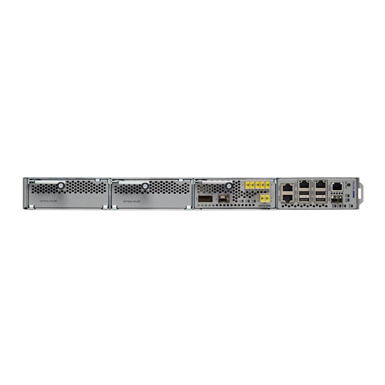
- Page 7 Cisco NCS 1001 Overview Cisco NCS 1001 Overview Figure 2: Cisco NCS 1001 Front View UDC (user data channel) for optical modules 1 and 2 Two USB 2.0 ports and one UDC for optical module 3 Two USB 2.0 ports and one 10/100/1000 LAN electrical management interface...
-
Page 8: Safety Labels
• Weight of control card: 1.5 kg Safety Labels Cisco NCS 1000 Series chassis is classified as Hazard Level 1M as per IEC 60825-2 and Laser Class 1M as per IEC 60825-1, since it includes pluggable optical modules Class 1 or Class 1M. - Page 9 Safety Labels Figure 4: Class 1/1M Laser Product Label This section explains the significance of the safety labels attached to the NCS 1001 chassis. The faceplates of the chassis are clearly labeled with warnings about the laser radiation levels. You must understand all warning labels before working on the chassis.
-
Page 10: Optical Amplifier Module
Safety Precaution for Laser Radiation Cisco NCS 1000 Series chassis is classified as Hazard Level 1M as per IEC 60825-2 and Laser Class 1M as per IEC 60825-1, since it may include embedded or pluggable optical modules Class 1 or Class 1M. - Page 11 The following table describes the mapping of controllers and optical ports for the optical amplifier module. Controller Optical Ports Ots 0/slot/0/0 • COM-RX (booster input) • COM-TX (preamplifier output) Ots 0/slot/0/1 • LINE-RX (preamplifier input) • LINE-TX (booster output) Hardware Installation Guide for Cisco NCS 1001...
-
Page 12: Protection Switching Module
COM input and output port [COM - RX, TX] Status LED The following table describes the mapping of controllers and optical ports for the protection switching module. Controller Optical Ports Ots 0/slot/0/0 COM-TX Hardware Installation Guide for Cisco NCS 1001... -
Page 13: Optical Time Domain Reflectometer Module
Protected path input and output port [P - RX, TX] Optical Time Domain Reflectometer Module Optical Time Domain Reflectometer (OTDR) is a line card supported in NCS 1001. The line card contains 2x bidirectional OTDRs and 2x filter that combines C-band, OSC, and OTDR filters and splits OSC and OTDR. - Page 14 Cisco NCS 1001 Overview Optical Time Domain Reflectometer Module Figure 10: OTDR Front View OTDR1 interface LED status OTDR2 interface Hardware Installation Guide for Cisco NCS 1001...
-
Page 15: Usb Passive Inventory
Multiplexer/Demultiplexer Patch Panel-C-band When the supported passive module is connected to the front panel port of NCS 1001, the module is discovered and the inventory data is read from the USB device. The user can view the details of passive module such as PID, Description, Serial Number, and Version ID using the show inventory command. -
Page 16: Product Ids
CWDM 1510-nm SFP; Gigabit Ethernet 1 and 2 Gb Fibre Channel CWDM-SFP-1610 CWDM 1610-nm SFP; Gigabit Ethernet 1 and 2 Gb Fibre Channel ONS-SC-Z3-1610= SFP OC-48/STM-16/GE, CWDM, 1610 nm ONS-SI-GE-LX= SFP 1000BASE-LX Gigabit Ethernet, 1310 nm, SM, I-TEMP Hardware Installation Guide for Cisco NCS 1001... -
Page 17: Leds In Cisco Ncs 1001
The control card is not present or not properly inserted. Amber Blinking The software is not operating correctly as the control card may not be correctly inserted. Amber Solid The control card, BIOS, and software are functional. Hardware Installation Guide for Cisco NCS 1001... - Page 18 Cisco NCS 1001 Overview LEDs in Cisco NCS 1001 Hardware Installation Guide for Cisco NCS 1001...
-
Page 19: Prepare To Install Cisco Ncs 1001
Unpack and Verify Cisco NCS 1001 Procedure Step 1 When you receive Cisco NCS 1001 equipment at the installation site, open the top of the box. The Cisco Systems logo is on the side of the box. Step 2 Remove accessories and foam inserts from the box. The box contains Cisco NCS 1001 and other items needed for installation. - Page 20 • The cable connectors, management ports, console ports, and power connectors are not damaged. • The SFP cages on the front panel are not damaged. • Verify that outstanding scratch, mark, bend, discoloration or deformation has not occurred to NCS 1001. Step 6 If there is any damage, call your Cisco sales engineer for a replacement.
-
Page 21: Install Cisco Ncs 1001
C H A P T E R Install Cisco NCS 1001 This chapter describes the procedures to install Cisco NCS 1001. • Rack Compatibility, on page 17 • Install NCS 1001-K9 into EIA/ANSI Rack, on page 19 • Install Four Post Slider into EIA/ANSI Rack, on page 23 •... - Page 22 Figure 14: EIA/ANSI (19" and 23") Rack specification Rack Type Rack Front Opening X Rack Mounting Hole Mounting Flange Center-Center Y Dimension Z 19" racks 450.8mm (17.75") 465mm (18.312") 482.6mm (19") 23" racks 552.45mm (21.75") 566.7mm (22.312") 584.2mm (23") Hardware Installation Guide for Cisco NCS 1001...
-
Page 23: Install Ncs 1001-K9 Into Eia/Ansi Rack
The front and rear vertical rails of four post racks must be within this range (547 to 847 mm) to install NCS 1001. NCS 1001 cannot be installed on a four post rack if the distance between rails is outside this limit. - Page 24 1.5 N-m (13.25 in-lbs) for 48-2406-01 screws. Figure 16: Sliding Edge Sliding edge Screws for sliding edge (part number - 48-0471-01) The edge always need to be facing bottom side on both the sides. Hardware Installation Guide for Cisco NCS 1001...
- Page 25 Fix the Grounding extender to the chassis with the screws (48-1142-01) and tighten them to a torque value of 2.5 - 3.4 N-m (22.0 - 30.0 in-lbs). Note The grounding extender must be assembled before installing NCS 1001 into the rack. Figure 18: Grounding Extender The counter sink surface must face outside as per the figure.
- Page 26 It is recommended to assemble the empty chassis to the rack for easy handling. Figure 19: NCS 1001 Chassis Assembly into Two or Four Post 19" or 23" Rack Ground lug extender must be assembled before inserting the chassis. See...
-
Page 27: Install Four Post Slider Into Eia/Ansi Rack
Check for the left/right marking on the sliders. This is left front sliding rail. Check for the left/right marking on the sliders. This is left rear sliding rail. Step 2 Prepare the four post slider. Hardware Installation Guide for Cisco NCS 1001... - Page 28 Once the shoulder rivets are aligned, slide in the sliders as shown in the arrow mark. Step 3 Integrate the slider to the four post 19" rack. Figure 22: Slider Integration to the Four Post 19" Rack Left side four-post slide assembly Hardware Installation Guide for Cisco NCS 1001...
- Page 29 Figure 23: Mating for the Four Post 19" Rack Edge surface of the rack Inner surface of the sliding bracket Step 4 Integrate the slider to the four post 23" rack. Hardware Installation Guide for Cisco NCS 1001...
- Page 30 Slider fixing screws (part number - 48-101524-01) (For 23" rack) Ensure that the edge surface of the adapter and the inner surface of the sliding rail Note are properly mated while assembling the sliding rail. Hardware Installation Guide for Cisco NCS 1001...
-
Page 31: Install Two Post Slider Into Eia/Ansi Rack
Figure 25: Mating for the Four Post 23" Rack Edge surface of the adapter Inner surface of the sliding bracket Install Two Post Slider into EIA/ANSI Rack Procedure Step 1 Identify the two post slider. Hardware Installation Guide for Cisco NCS 1001... - Page 32 Check whether the two post width is 5" OR 3". If the width is 5", use the default slider assembly for 5". b) If the post width is 3", modify the right/left sliders as shown below. Step 2 Prepare the two post slider. Figure 27: Two Post Slider Preparation Hardware Installation Guide for Cisco NCS 1001...
- Page 33 The two post slider is ready to use on 3" width post. This assembly procedure is the same for right or left sliders. Step 3 Integrate the slider to the two post 19" rack. Hardware Installation Guide for Cisco NCS 1001...
- Page 34 Slider fixing screws (part number - 48-101524-01) Note Ensure that the edge surface of the 19" rack and the inner surface of the sliding rail are properly mated while assembling the sliding rail. Hardware Installation Guide for Cisco NCS 1001...
- Page 35 Install Two Post Slider into EIA/ANSI Rack Figure 29: Mating for the Two Post 19" Rack Edge surface of the rack Inner surface of the sliding bracket Step 4 Integrate the slider to the two post 23" rack. Hardware Installation Guide for Cisco NCS 1001...
- Page 36 Slider fixing screws (part number - 48-101524-01) Note (For 23" rack) Ensure that the edge surface of the adapter and the inner surface of the sliding rail are properly mated while assembling the sliding rail. Hardware Installation Guide for Cisco NCS 1001...
-
Page 37: Ground Ncs 1001
Edge surface of the adapter Inner surface of the sliding bracket Ground NCS 1001 Caution When terminating the frame ground, do not use soldering lug connectors, screwless (push-in) connectors, quick connect connectors, or other friction-fit connectors. Hardware Installation Guide for Cisco NCS 1001... -
Page 38: Cable Guide
Attach the other end of the shelf ground cable to the bay frame using a dual-hole lug connector according to the equipment rack frame specifications. Cable Guide The attachment of the cable guide is as shown below. Hardware Installation Guide for Cisco NCS 1001... -
Page 39: Power Supply
Power Supply NCS 1001 has two slots for 600W AC redundant Power Supply Units (PSU). It is sufficient to have a single PSU inserted in the chassis to support all the features and provide power to all the pluggable modules. When only one PSU is inserted in the chassis, the Power Module Redundancy Lost major alarm is raised. -
Page 40: Connect Ac Power To Ncs 1001
Connect AC Power to NCS 1001 Caution NCS 1001 relies on the protective devices in the building installation to protect against short circuit, overcurrent, and ground faults. Ensure that the protective devices comply with local and national electrical codes. The voltage rating value for AC power ranges either between 200 V to 240 V or between 100 V to 127 V depending on the standards in various countries. - Page 41 Install Cisco NCS 1001 Connect AC Power to NCS 1001 Figure 35: Connecting AC Power AC power cord Cable clamp Tie mount Final assembly Hardware Installation Guide for Cisco NCS 1001...
-
Page 42: Connect Dc Power To Ncs 1001
Connect DC Power to NCS 1001 Caution NCS 1001 relies on the protective devices in the building installation to protect against short circuit, overcurrent, and ground faults. Ensure that the protective devices comply with local and national electrical codes. The system accepts a nominal input voltage of -48 VDC or -60 VDC at 15A, with an operational tolerance range of -40.5 to -72 VDC. -
Page 43: Related Information
Ensure that either the fuse is inserted or the circuit breaker is in the ON position. Verify that the Green LED on the PSU is on. Related Information For more information on NCS 1001 including specifications, see the data sheet. - Page 44 Install Cisco NCS 1001 Related Information Hardware Installation Guide for Cisco NCS 1001...
-
Page 45: Replace Cisco Ncs 1001 Components
C H A P T E R Replace Cisco NCS 1001 Components This chapter describes the procedures to replace Cisco NCS 1001 components. • Insert Power Supply, on page 41 • Remove Power Supply, on page 42 • Insert Fans, on page 43 •... -
Page 46: Remove Power Supply
The inlet temperature of system during replacement must be less than 40 deg Celsius at sea level. The replacement time decreases for higher altitudes. Note In case of PSU failure, the failed PSU needs to be physically replaced within 2 minutes. Figure 39: Hot Area on PSU Faceplate Hardware Installation Guide for Cisco NCS 1001... -
Page 47: Insert Fans
Use this procedure to insert the fans. Figure 41: Insert Fans Push the fan into the fan slot as shown (slots 0, 1, 2, or 3) Ensure that the fan connector always faces upwards Hardware Installation Guide for Cisco NCS 1001... -
Page 48: Remove Fans
Remove Fans Note Cisco NCS 1001 has fan redundancy protection mechanism against a single fan failure for up to 96 hours. The inlet temperature of system during replacement must be less than 40 deg Celsius at sea level. The replacement time decreases for higher altitudes. - Page 49 Ejector lever. Rotate and push ejector lever to engage control card to the connector. Control card faceplate. Push this surface area with additional force needed to engage control card. Fan tray Fans The control card is properly seated. Hardware Installation Guide for Cisco NCS 1001...
-
Page 50: Remove Control Card
Apply pressure on the control card faceplate to complete the insertion. Step 5 Ensure that the control card faceplate is aligned to the top cover edge of NCS 1001. Step 6 Verify that the position of the ejector is final. - Page 51 Step 2 Unfasten the fan tray screws as shown. Step 3 Pull out the fans from the chassis as shown. Step 4 Use the ejector lever to eject the control card from the chassis. Hardware Installation Guide for Cisco NCS 1001...
-
Page 52: Remove And Replace Ssd
Remove and Replace SSD Note If the SSD is removed, it needs to be physically replaced within 10 minutes. If NCS 1001 runs without the SSD, the SSD metallic cover must be placed to close the SSD slot. To remove a SSD:... -
Page 53: Insert Optical Modules
Use the ejector lever force to push the module inside. Step 4 When the ejector is aligned to the faceplate, fasten the captive screw in the clockwise direction to complete the assembly. Figure 46: Insert Optical Modules Ejector lever Captive screw Hardware Installation Guide for Cisco NCS 1001... -
Page 54: Remove Optical Modules
Use the ejector lever to pull the module outside. Step 3 Once the module is partially out, pull the module from the chassis. Figure 47: Remove Optical Modules Ejector lever 2 and 3 Captive screw Hardware Installation Guide for Cisco NCS 1001... -
Page 55: Filler Modules
Figure 48: Filler Modules Optical filler module PSU filler module The insertion and removal procedure of the optical filler modules (left) and the PSU filler modules (right) is the same as the module replacement. Hardware Installation Guide for Cisco NCS 1001... -
Page 56: Cable Routing
When NCS 1001 becomes faulty, contact TAC to open a Return Material Authorization (RMA) request. Before opening a RMA request, the user can securely wipe data in NCS 1001 disks using the Secure Erase feature. The Secure Erase feature is supported from BIOS version v13.10. - Page 57 Wipe Data in Disk Using Secure Erase Before you begin The NCS 1001 unit that is planned for RMA must be taken out of the data center and the network. The user must access NCS 1001 only using the console port.
- Page 58 Replace Cisco NCS 1001 Components Wipe Data in Disk Using Secure Erase Hardware Installation Guide for Cisco NCS 1001...
Need help?
Do you have a question about the NCS 1001 and is the answer not in the manual?
Questions and answers