Cisco NCS 1001 Start Manual
Hide thumbs
Also See for NCS 1001:
- Hardware installation manual (58 pages) ,
- Configuration manual (36 pages) ,
- Manual (14 pages)
Advertisement
Quick Links
Advertisement

Related Manuals for Cisco NCS 1001


Summary of Contents for Cisco NCS 1001
- Page 1 Quick Start Guide for Cisco NCS 1001...
- Page 2 Cisco NCS 1001 Overview Cisco NCS 1001 (NCS1001-K9) is 1 RU chassis that addresses the growing bandwidth needs of data center DWDM applications. It provides a DWDM line system that is optimized for data center environments and is optimized for point-to-point applications at maximum capacity.
- Page 3 The empty slots must be inserted with the filler optical modules or filler PSUs as appropriate to guarantee Caution safety and system cooling compliance. See Figure 1: Cisco NCS 1001 Front View, on page 3 Figure 3: Cisco NCS 1001 Rear View, on page 4 to identify the slots for optical modules and PSUs respectively.
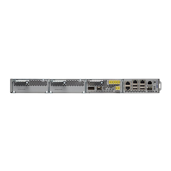
- Page 4 The slot numbers are also specified on the front panel label. Figure 2: Cisco NCS 1001 Front View UDC (user data channel) for optical modules 1 and 2 Two USB 2.0 ports and one UDC for optical module 3 Two USB 2.0 ports and one 10/100/1000 LAN electrical management interface...
- Page 5 Both the power supply modules shall be AC/DC or DC/DC. Mixed configuration is not allowed. Benefits NCS 1001 provides the following benefits. • Up to 23dBm output power to allow for +3dBm per channel fiber launch power and maximum optical performance for high baud rate and higher order modulation format transponders.
- Page 6 Physical Characteristics • Width: 17.44” (442.9 mm) • Depth: 23.64” (600.5 mm) • Height: 1 RU • Weight without power supply unit: 8.2 kg • Weight with two power supply units: 10.5 kg • Weight of AC PSU: 1.162 kg •...
- Page 7 Revised: April 13, 2018, LEDs in Cisco NCS 1001 State Description Green The unit is operating correctly. Yellow The unit has one or more errors detected. Power is not applied to the unit. Blue The unit needs attention. The unit does not need attention.
- Page 8 Revised: April 13, 2018, Review Safety Warnings Review the safety warnings available at Regulatory Compliance and Safety Information for Cisco NCS 1000 Series.
- Page 9 Unpack and Verify Cisco NCS 1001 Procedure Step 1 When you receive Cisco NCS 1001 equipment at the installation site, open the top of the box. The Cisco Systems logo is on the side of the box. Step 2 Remove accessories and foam inserts from the box. The box contains Cisco NCS 1001 and other items needed for installation.
- Page 10 In case of a closed cabinet, the cabinet must support the thermal management or front/rear doors need to have 70% perforation. Closed cabinets must have adequate airflow to dissipate maximum power from equipments in a fully-equipped cabinet. NCS 1001-K9 shall be installed maintaining a minimum clearance of 5mm above and below the chassis. Before You Begin...
- Page 11 Procedure Step 1 Identify and attach the sliding edge for the 2/4 post rack. Step 2 Attach the sliding rail and L bracket to the left and right of the chassis using the screws (48-0471-01 and 48-2406-01) and tighten them to a torque value of 0.65 N-m (5.9 in-lbs) for 48-0471-01 screws and torque value of 1.5 N-m (13.25 in-lbs) for 48-2406-01 screws.
- Page 12 Figure 6: Fixing L Bracket Right L Bracket Screws for L Bracket (part number - 48-2406-01) Left L Bracket Step 3 Fix the Grounding extender to the chassis with the screws (48-1142-01) and tighten them to a torque value of 2.5 - 3.4 N-m (22.0 - 30.0 in-lbs).
- Page 13 The grounding extender must be assembled before installing NCS 1001 into the Note rack. Figure 7: Grounding Extender The counter sink surface must face outside as per the figure. Grounding extender Extender screws (part number - 48-1142-01) Step 4 Install four post slider or two post slider as required.
- Page 14 It is recommended to assemble the empty chassis to the rack for easy handling. Figure 8: NCS 1001 Chassis Assembly into Two or Four Post 19" or 23" Rack Ground lug extender must be assembled before inserting the chassis. See...
- Page 15 During assembly of the unit, rest the sliding edge on the sliding rail groove on either side. Push the chassis gently onto the rack until the faceplate makes in contact with the rack surface. Slider fixing screws (part number - 48-101524-01). Step 6 As soon as the chassis is completely inserted, fasten the chassis with two screws (48-101524-01) on each side of the bracket and tighten them to a torque value of 3.4 N-m (30 in-lbs).
- Page 16 Revised: April 13, 2018, Install Four Post Slider into EIA/ANSI Rack Procedure Step 1 Identify the four post slider. Figure 9: Four Post Slider Identification Check for the left/right marking on the sliders. This is left front sliding rail. Check for the left/right marking on the sliders. This is left rear sliding rail.
- Page 17 Step 2 Prepare the four post slider. Figure 10: Four Post Slider Preparation Align the sliders left front-left rear or right front-right rear as shown. Flange facing side during assembly. SLIDE Once the shoulder rivets are aligned, slide in the sliders as shown in the arrow mark.
- Page 18 Step 3 Integrate the slider to the four post 19" rack. Figure 11: Slider Integration to the Four Post 19" Rack Left side four-post slide assembly Right side four-post slide assembly Slider fixing screws (part number - 48-101524-01)
- Page 19 Ensure that the edge surface of the 19" rack and the inner surface of the sliding rail are properly mated while Note assembling the sliding rail. Figure 12: Mating for the Four Post 19" Rack Edge surface of the rack Inner surface of the sliding bracket...
- Page 20 Step 4 Integrate the slider to the four post 23" rack. Figure 13: Slider Integration to the Four Post 23" Rack The formed surface must always face the inner side of the rack post Slider fixing screws (part number - 48-101524-01)
- Page 21 (For 23" rack) Ensure that the edge surface of the adapter and the inner surface of the sliding rail are properly Note mated while assembling the sliding rail. Figure 14: Mating for the Four Post 23" Rack Edge surface of the adapter Inner surface of the sliding bracket...
- Page 22 Revised: April 13, 2018, Install Two Post Slider into EIA/ANSI Rack Procedure Step 1 Identify the two post slider. Figure 15: Two Post Slider Identification Check for the left/right marking on the sliders. a) Check whether the two post width is 5" OR 3". If the width is 5", use the default slider assembly for 5".
- Page 23 b) If the post width is 3", modify the right/left sliders as shown below. Step 2 Prepare the two post slider. Figure 16: Two Post Slider Preparation Align the rivet with key hole. Do not insert any rivet inside this. a) Unfasten the 4X screws as shown above.
- Page 24 Step 3 Integrate the slider to the two post 19" rack. Figure 17: Slider Integration to the Two Post 19" Rack...
- Page 25 Left side four post slide assembly...
- Page 26 Right side four post slide assembly Slider fixing screws (part number - 48-101524-01) Ensure that the edge surface of the 19" rack and the inner surface of the sliding rail are properly mated while Note assembling the sliding rail. Figure 18: Mating for the Two Post 19" Rack Edge surface of the rack Inner surface of the sliding bracket...
- Page 27 Step 4 Integrate the slider to the two post 23" rack. Figure 19: Slider Integration to the Two Post 23" Rack The formed surface must always face the inner side of the rack post Slider fixing screws (part number - 48-101524-01)
- Page 28 Note (For 23" rack) Ensure that the edge surface of the adapter and the inner surface of the sliding rail are properly mated while assembling the sliding rail. Figure 20: Mating for the Two Post 23" Rack Edge surface of the adapter Inner surface of the sliding bracket...
- Page 29 Attach one end of the shelf ground cable (#8 AWG cable) to the ground point using the specified dual-hole lug connector. Figure 7: Grounding Extender, on page Figure 21: NCS 1001 Ground Lug The orientation of the lug cable is always at the bottom side.
-
Page 31: Power Supply
Power Supply NCS 1001 has two slots for 600W AC redundant Power Supply Units (PSU). It is sufficient to have a single PSU inserted in the chassis to support all the features and provide power to all the pluggable modules. When only one PSU is inserted in the chassis, the Power Module Redundancy Lost major alarm is raised. - Page 32 Revised: April 13, 2018, Connect AC Power to NCS 1001 NCS 1001 relies on the protective devices in the building installation to protect against short circuit, Caution overcurrent, and ground faults. Ensure that the protective devices comply with local and national electrical codes.
- Page 33 Step 2 Attach the AC power cable to the cable connector in the AC power module. Step 3 Close the cable clamp to secure the power cable. Figure 23: Connecting AC Power...
- Page 35 AC power cord Cable clamp Tie mount Final assembly Step 4 Ensure that the lockout device is removed if installed and turn on the circuit breaker(s) to the shelf. Verify that the Green LED on the PSU is on.
- Page 36 Revised: April 13, 2018, Connect DC Power to NCS 1001 NCS 1001 relies on the protective devices in the building installation to protect against short circuit, Caution overcurrent, and ground faults. Ensure that the protective devices comply with local and national electrical codes.
- Page 37 Step 1 Verify that the correct fuse panel is installed in the top mounting space. Step 2 Measure and cut the cables as needed to reach NCS 1001 from the fuse panel. Step 3 Dress the power according to local practice.
-
Page 38: Related Information
Revised: April 13, 2018, Related Information For more information on NCS 1001 including specifications, see the data sheet. - Page 39 © 2018 Cisco Systems, Inc. All rights reserved.
- Page 40 Cisco Systems, Inc. Cisco Systems (USA) Pte. Ltd. Cisco Systems International BV San Jose, CA 95134-1706 Singapore Amsterdam, The Netherlands Cisco has more than 200 offices worldwide. Addresses, phone numbers, and fax numbers are listed on the Cisco Website at www.cisco.com/go/offices.
Need help?
Do you have a question about the NCS 1001 and is the answer not in the manual?
Questions and answers