
Subscribe to Our Youtube Channel
Related Manuals for JRC JUE-501


Summary of Contents for JRC JUE-501
- Page 1 JUE - 501/JUE-251 INMARSAT FleetBroadband FB500/FB250 Maritime Satellite Communication Terminal INSTRUCTION MANUAL...
- Page 3 ABOUT YOUR SAFETY CAUTIONS AGAINST HIGH VOLTAGE Radio and radar devices are operated by high voltages of anywhere from a few hundred volts up to many hundreds of thousands of volts. Although there is no danger with normal use, it is very dangerous if contact is made with the internal parts of these devices.
- Page 4 FIRST AID ☆Note points for first aid Unless there is impending danger leave the victim where he or she is, then begin artificial respiration. Once you begin artificial respiration, you must continue without losing rhythm. Make contacts with the victim cautiously, there is a risk that you may get electrocuted. Switch off the machinery and then move the victim away slowly if you must.
- Page 5 ☆If the victim has a pulse but is not breathing (1)Place the victim’s head facing backward (place something under the neck like a pillow). (2)Point the chin upward to widen the trachea. (3)Pinch the victim’s nose, take a deep breath, then put your mouth over the victim’s mouth and exhale completely, making sure that your mouth completely covers the victim’s mouth.
- Page 6 ☆If the victim has no pulse and is not breathing If the victim has no pulse, his or her pupils are dilated, and if you cannot detect a heartbeat, the heart may have stopped; beginning artificial respiration is critical. (1) Put both hands on the diaphragm, with hands on top it and keeping both arms straight each other (If your elbows are bent;...
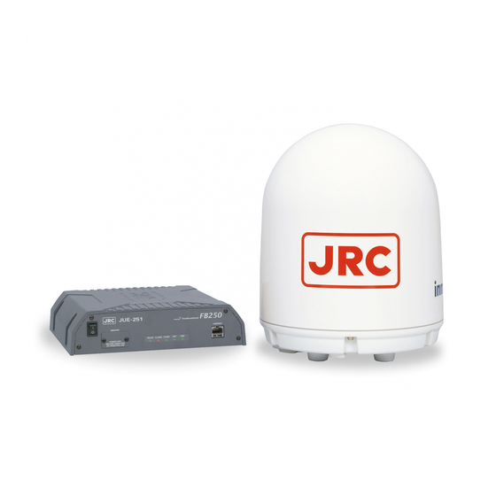
- Page 7 Short Message Service (SMS). (*) is available only for JUE-501. The JUE-501/JUE-251 is packaged and shipped under strict quality control with inspection criteria to deliver the equipment with highest quality, performance, and reliability needed to meet our customer’s requirements and satisfaction.
- Page 8 BEFORE OPERATION (1) About this instruction manual Before operating this equipment, read the manual carefully to ensure correct instruction. This book is useful for troubleshooting, too. (2) Concerning the symbols This manual uses the following symbols to explain the correct operation and to help prevent injury or damage to property.
- Page 9 Concerning warning label Warning labels are put on the JUE-501/JUE-251 ADE and BDE. Do not take off, destroy, or modify these labels. <Warning Label of JUE-501 ADE> (The illustration of upper part shows the safety Procedure for removing Radome from ADE.)
- Page 10 <Warning Label of JUE-501 BDE> Note 2) Note 3) Note 4) Note 1) <Warning Label of JUE-251 BDE> Note 2) Note 3) Note 4) Note 1) Notes 1) This mark means this equipment clears the directive of Restricting the use of Hazardous Substances (RoHS).
- Page 11 However we caution you to understand that your communication data might be intercepted by special technology and unauthorized access to the communication theory. There are some additional and optional functions of the JUE-501/JUE-251 that shall be released in the near future for evaluation.
- Page 12 JUE-251 and stop transmitting. If an external matter, such as metal fragments, water, liquid, etc., infringes into your JUE-501/JUE-251, turn off the power and contact the dealer or agent you purchased the equipment from. Continuous operation may cause fire, electrical...
- Page 13 Use the specified power supply voltage only (+21VDC to +31VDC), otherwise trouble, fire, or electric shock or malfunction may occur. Do not troubleshoot or repair the internal equipment of the JUE-501/JUE-251 by yourself. Any electrical work by any person other than our trained maintenance staff may cause fire or abnormal operation of this equipment or electrical shock for you.
- Page 14 CAUTION Before using, read this instruction manual. Incorrect operation may cause improper working operation or malfunction. When a fault has been detected, refer to the “Appendix N. Trouble shooting and FAQ”. If it is not improved, turn OFF and ON the power switch of main unit to reboot.
- Page 15 Emergency Calling (1) About 505 Emergency Calling Inmarsat has introduced 505 Emergency Calling for the FBB terminals. In a time of distress, a seafarer need only dial "505" and press either the offhook ( ) or # key- selected for its similarity to "SOS"...
- Page 16 This page is remained as a blank.
-
Page 17: Table Of Contents
2.4 Dimensional drawing (JUE-501/JUE-251 standard components) ..2-6 2.4.1 ADE (Above Deck Equipment)JUE-501[GSC-511] ....2-6 2.4.2 ADE (Above Deck Equipment)JUE-251[GSC-251] ....2-7 2.4.3 BDE (Below Deck Equipment) JUE-501 [GSC-512] ....2-8 2.4.4 BDE (Below Deck Equipment) JUE-251 [GSC-252] ....2-9 2.4.5 Handset [NQW-267] ..............2-10 2.4.6 Junction Board [CQD-2243] ............. -
Page 18: Table Of Contents
3.5 Communication terminals ..............3-13 3.5.1 Terminal requirements ..............3-13 3.5.2 Usage environment ..............3-14 3.6 Handset menu ................... 3-14 4. Getting started ..................4-1 4.1 Connecting terminals and power on ..........4-2 4.1.1 Connecting terminals with cables ..........4-2 4.1.2 Setting/removing SIM card ............ - Page 19 5.2.4 Handling Call Waiting ..............5-35 5.2.5 Holding on the line ..............5-35 6 Web Menu System ................6-1 6.1 Connect Your PC to JUE-501/JUE-251 ..........6-2 6.2 Web Screen ..................6-6 6.3 Login/Logout ..................6-9 6.4 Menus for all Users ................6-11 6.4.1 Dashboard...
- Page 20 6.5.5.1 Set WAN Profile ........6-53 (WAN Profile Screen) 6.5.5.2 Set Packet Filter ........6-61 (Packet Filter Screen) 6.5.5.3 Set Permanent Connection ....6-64 (Always Activate Screen) 6.5.5.4 Establish Remote Connection .... 6-66 (Remote Activate Screen) 6.5.5.5 Set LAN Group .........
- Page 21 7.7.2 Call Log authentication and deletion .......... 7-29 7.7.3 Setting telecom rates ..............7-30 7.8 Alarmpack menu ................7-31 7.8.1 Unit selection menu for Alarm Pack ........... 7-32 7.9 Admin menu ..................7-35 7.9.1 Terminal menu ................7-36 7.9.1.1 Delivery setting ..............7-37 7.9.1.2 Local Time setting ..............
- Page 22 D Software updating procedure .............. D-1 E Return to the factory default ..............E-1 F Default value list (BDE-App 01.00) ............. F-1 G JUE-501/251 VPN setting ..............G-1 H How to connect PPPoE Connection ..........H-1 I How to connect Bridge Connection ............I-1 J Multi-Voice Service ................
-
Page 23: The Inmarsat Service Systems
1. The Inmarsat Service Systems 2. Introduction of the JUE-501/JUE-251 3. Appearance 4. Getting Started 5. How to use the Telephone / FAX 6. Web Menu System 7. Handset Menu System 8. Using ISDN port 9. Maintenance 10. After-sales service 11. -
Page 25: Outline
A geostationary satellite is placed on each Ocean Region (excluded spare satellites). The adjacent Ocean Regions have overlapped area of satellite regions. Suitable Ocean Region (satellite region) is automatically selected when JUE-501/JUE-251 positions in overlapped area. Overlap Ocean Region Europe, Middle... -
Page 26: The Inmarsat Fleetbroadband System
1. Inmarsat Service systems 1.1.2 The Inmarsat FleetBroadband System The Inmarsat network system consists of NCS, NOC, SCC, TT&C, and SAS. Functions of each facility are as follows: 1) Network Coordination Station (NCS) The NCS assigns communication channels between the Mobile Earth Stations (MES) and Satellite Access Station (SAS). -
Page 27: The Inmarsat Fleet Broadband Services
Inmarsat FleetBroadband provides service shown below. Packet Switched service (PS), Circuit Switched service (CS), and Short Message Service (SMS) can be used simultaneously. JUE-501/JUE-251 supports a maximum of 11 PS connections and one CS connection at the same time. Packet switched service (PS) •... -
Page 28: Important Reminder For Using Jue-501/Jue-251
Short Message Service Send and receive text messages up to 160 characters. • Charged by message. 1.3 Important reminder for using JUE-501/JUE-251 NOTE • Communication failure due to MCA wireless system interference could occur at the coast of Japan urban area. -
Page 29: Emergency Calling
1. Inmarsat Service systems 1.4 Emergency Calling 1.4.1 505 Emergency Calling Inmarsat has introduced 505 Emergency Calling for the FBB terminals. In a time of distress, a seafarer need only dial "505" and press either the offhook ( ) or # key- selected for its similarity to "SOS"... - Page 30 1. Inmarsat Service systems This page is remained as a blank.
-
Page 31: Introduction Of The Jue-501/Jue-251
JUE-501/JUE-251 is shipped with strict quality control and inspection to provide the high quality for consumers. JRC would like to believe you to make long use of the terminal with your satisfaction. Network service is managed by Inmarsat co. or other network service providers. Network service may be changed or terminated without prior notice due to the circumstances of the network service providers. -
Page 32: Features
* The service available to you is depending on the contract. Stylish, Light weight, Space-saving, and Gyro-less The JUE-501/JUE-251 can be installed on vessels of all sizes due to the compact and lightweight design of the ADE. The adoption of an active and Gyro-less antenna structure makes this unit a perfect fit for small vessels. - Page 33 2. Introduction of JUE-501/JUE-251 2.3 Cable connection diagram and components List 2.3.1 Cable connection diagram ◆ Fig. 2.3.1 Cable connection diagram (JUE-501)
-
Page 34: Components List
2. Introduction of JUE-501/JUE-251 2.3.2 Components list Table 2.3.2 Components list Name of equipment Type Q’ty Standard JUE-501 GSC-511 Components JUE-251 GSC-251 JUE-501 GSC-512 JUE-251 GSC-252 Handset NQW-267 PSU cable 7ZCSC0222B (between EXT PSU and BDE main unit) Instruction Manual... - Page 35 2. Introduction of JUE-501/JUE-251 External Buzzer NCE-6824A Max 4 Voice Distress Button NQE-3301 Max 2 Wall mount adapter for VDB 7ZZSC0095 Max 2 Instruction Manual (Japanese) 7ZPSC0428 Installation Manual (Japanese) 7ZPSC0430 Quick Reference Guide (Japanese) 7ZPSC0432 *CFQ-3922A series (15m to 45m, 5m interval、5D)、CFQ-3923Aseries (70m and 100m、10D)are available as options.
-
Page 36: Dimensional Drawing (Jue-501/Jue-251 Standard Components)
2. Introduction of JUE-501/JUE-251 2.4 Dimensional drawing (JUE-501/JUE-251 standard components) 2.4.1 ADE (Above Deck Equipment) JUE-501[GSC-511] Unit: mm Mass: Approx.20kg Fig. 2.4.1 Appearance of JUE-501 ADE (GSC-511) -
Page 37: Ade (Above Deck Equipment)Jue-251[Gsc-251]
2. Introduction of JUE-501/JUE-251 2.4.2 ADE (Above Deck Equipment) JUE-251[GSC-251] Unit: mm Mass: Approx.4.7kg Fig. 2.4.2 Appearance of JUE-251 ADE (GSC-251) -
Page 38: Bde (Below Deck Equipment) Jue-501 [Gsc-512]
2. Introduction of JUE-501/JUE-251 2.4.3 BDE (Below Deck Equipment) JUE-501[GSC-512] Unit: mm Mass: approx. 4.5kg Fig. 2.4.3 Appearance of JUE-501 BDE (GSC-512) -
Page 39: Bde (Below Deck Equipment) Jue-251 [Gsc-252]
2. Introduction of JUE-501/JUE-251 2.4.4 BDE (Below Deck Equipment) JUE-251[GSC-252] Unit: mm Mass: approx. 4.5kg Fig. 2.4.4 Appearance of JUE-251 BDE (GSC-252) -
Page 40: Handset [Nqw-267]
2. Introduction of JUE-501/JUE-251 2.4.5 Handset [NQW-267] 4-Mounting holes Unit: mm Mass. approx. 0.5kg Fig. 2.4.5 Handset 2-10... -
Page 41: Junction Board [Cqd-2243]
2. Introduction of JUE-501/JUE-251 2.4.6 Junction Board [CQD-2243] Intentionally Blank. Unit: mm Mass: approx. 2.5 kg Fig.k2.4.6 Junction Board Fig. 2.4.6 Appearance of Junction Board (CQD-2243) 2-11... - Page 42 2. Introduction of JUE-501/JUE-251 2.4.7 Coaxial cable [CFQ-3922A5/CFQ-5924A3] Max.30mm Max.15mm Standard cable Standard cable JUE-251 JUE-501 Mass:2.5kg Mass:12.5kg CFQ-3922A5 CFQ-5924A3 Connector Cable Minimum Type Length Mass Remarks Dia. Dia. bending radius Standard for JUE-501 CFQ-3922A5 50m±0.5m 30mm 15mm 12.5kg or less...
-
Page 43: Appearance
3. Appearance 3. Appearance In this section, the composition of the JUE-501/JUE-251 and terminal equipments are explained. Above Deck Equipment (ADE): Antenna unit and radome (Antenna Cover) Blow Deck Equipment (BDE): Main unit Coaxial cable: A Cable connects ADE to BDE... - Page 44 3. Appearance 3.2 BDE Main unit Main unit appearance Front view Rear view Fig. 3.2a Main unit appearance Front view 1. Power Switch 3. LEDs 2. SIM Card slot 4. Handset port Fig 3.2b Main unit front view...
- Page 45 3. Appearance Rear view 8. WRF connector 12. FUSE 6. Antenna cable 10. JRC LAN port 14. DC Power connector connector 13. VDB port 9. Ext WAN port 5. TEL1/2 port 11. User LAN port 7. ISDN Port 15. Earth Fig.
- Page 46 Connects with External WAN such as ESV. 10 JRC LAN port (RJ-45 type 8-PIN Modular Cable for Ethernet) Connects with JRC LAN. It creates additional value like remote maintenance or status monitor by connecting JRC products other than FBB. 11 User LAN port × 4 (RJ-45 type 8-PIN Modular Cable for Ethernet) Connects with user device such as user PC.
-
Page 47: Ade—Bde Connecting Cable
3. Appearance 3.3 ADE - BDE connecting cable *This cable can be connected to ADE and BDE in either direction. 50m (standard) for JUE-501 30m (standard) for JUE-251 Fig. 3.3 ADE-BDE connecting cable... -
Page 48: Handset
Fig 3.4a Handset and cradle Handset operation side consists of three sections: 3.4.1. LCD / LED section LCD/LED section screen displays JUE-501/JUE-251 user information. Functional LEDs indicate communication/apparatus status. button section 3.4.2. Functional button section Buttons in this section control basic functions of the Alpha-numeric JUE-501/JUE-251. -
Page 49: Lcd/Led Section
3. Appearance 3.4.1 LCD/LED section Functions of the LCD screens of the Handset. Common items for all screens are: 1 [Operational button] Displays operatable keys: 2 [Enter mode] Displays which key enter mode is accepted, Aa (alphabet mode), or nothing (numeric mode) is displayed. - Page 50 3. Appearance Table 3.4.1 Explanation of items displayed on screens Displayed items Contents 1 Operational button Displays when the scrolling-up/down or switching-left/right is available. Scroll the screen when up/down is displayed, with buttons. Switch the screen when left/right is displayed, with buttons.
- Page 51 3. Appearance 4 Condition of 1)Displays a bar graph of signal reception level by seven (7) grades. It blinks reception when antenna was hidden from satellite by obstructions. Communication Number of bars Impossible (no reception) Possible to communicate but unstable Possible to communicate but unstable Possible to communicate stably Possible to communicate stably...
- Page 52 3. Appearance 8 Status of equipment Displays the status of equipment. Normally, this area displays below contents under waiting communication or under transmitting. Status of Displayed txt. Contents equipment Normal nnn/NNN Displays the used amount (nnn) and total capacity (NNN) of input characters of SMS Displayed only in SMS menu Abnormal ADE?
- Page 53 3. Appearance Lighting of LEDs Ready lamp: displays communication status ALARM lamp: indicates failure alert (available/non-available) Red light: Failure has occurred in the system. Green light: All communication services are (No light: The status is normal) available. Blinking Green: No service is available (starting system, calibrating cable, searching READY ALARM COMM satellite or registering SIM).
-
Page 54: Functional Button Section
3. Appearance 3.4.2 Functional button section This section describes function buttons except those for entering characters. Buttons and its function Switching button Switches enter mode, between alphabets and numbers. SMS button Reads, creates, sends, and deletes Short Message Service(SMS). Status button Makes direct access to STATUS menu. STATUS OK button Registers entered contents. -
Page 55: Communication Terminals
RJ-45 FAX). (Refer to p4-12 for Service type modification). Ethernet cable NOTE JUE-501/JUE-251 recognizes the type of Ethernet cable (cross or straight) automatically. Ethernet cable A maximum of total 32W PoE (Power over Ethernet) is available on User LAN. Fig. 3.5.1 Terminal requirements... -
Page 56: Usage Environment
A-law, μ-law Interface RJ-45 (S/T interface) 3.6 Handset menu On the JUE-501/JUE-251, various menu screens can be displayed and set, from Handset. Guest User cannot utilize the menus of Admin User Guest User: General user Admin User:User who is authorized to make settings of the JUE-501/JUE-251. -
Page 57: Getting Started
In Section 4.1, connecting the Handset and terminal devices to Main unit, and installing SIM card are described; and initial setting for communication is described in Section 4.2. NOTE JUE-501/JUE-251 has two types of satellite tracking mode, Signal tracking mode and Gyro tracking mode. Press MENU+3 button (Satellite menu) on the Handset. -
Page 58: Connecting Terminals And Power On
PC(s) connected with Ethernet port Fig.4.1.1 The Cable connection of each terminal NOTE The JUE-501/251 recognizes Ethernet cable type (cross or straight) automatically. • Service type of TEL1/2 port must be set properly according to the connected terminal • (telephone or FAX). (Refer to p4-12 for Service type modification). - Page 59 Connect your PC to User LAN port with Ethernet cable. Connecting VDR to JRC LAN port Connect VDR (produced by JRC) to JRC LAN port with Ethernet cable if needed. Connecting external WAN to Ext WAN port Connect external WAN to Ext WAN port with Ethernet cable if needed.
-
Page 60: Setting/Removing Sim Card
Please make sure that SIM card is inserted correctly before turning on the power every time. NOTE ・ JUE-501/JUE-251 will not work without a valid SIM card, which is furnished from the Distribution Partner. ・ Make sure that power switch is correctly turned off, before you set/remove the SIM card to/from main unit. - Page 61 4. Getting started SIM card removing procedure (After power is turned off) 1) Remove the SIM card protector by unscrewing cross-head screws on front panel. 2) Loosen the SIM card by sliding the black knob. 3) Push the SIM card and then it comes out. Remove the SIM card. 4) Restore the SIM card protector by driving the screws in.
-
Page 62: Power On
The READY LED on the front panel will light up in green and start blinking. After a while, the ANTENNA lamp will start blinking and then both lamps will stop blinking and light green. Although there is nothing wrong with JUE-501/JUE-251, turning on the switch makes some noise on ADE. - Page 63 Initialization of the unit may take more than 5 minutes to complete. During this time, "CS PS READY" may not be displayed on the screen. It is not abnormal status (the JUE-501/JUE-251 is executing the initialization, satellite search, and registering to the network).
-
Page 64: Screen Display Of Handset
4. Getting started 4.1.4 Screen display of Handset Turn on JUE-501/JUE-251 by pushing power switch off Main unit. If Gyro is being selected for tracking, refer to Appendix C.3. Initializing A LED of Main unit starts blinking. About 90 seconds later, initializing is started Initialize and blinking [Initialize] text is displayed. - Page 65 NOTE Carry out available countermeasure referring to [7.10.Other screen: TX alarm screen] (p7-77), when JUE-501/JUE-251 displays the below screen during communication. These screens indicate a failure has occurred on the communication system of the JUE-501/JUE-251. TX Alarm : Reset Fig. 4.1.4c TX alarm screen...
-
Page 66: Initial Setting For Communication
4. Getting started 4.2 Initial setting for communication Setting flow Mode setting of Guest and Admin (Chapter 4.2.1, p4-11) Ethernet port ISDN port Handset Go to Chapter8 (p8-1) Using ISDN port Go to Chapter6 Web Menu System (p6-1) Go to Chapter5 (p5-1) How to use the telephone/FAX Fig. -
Page 67: Mode Setting Of Guest And Admin
4.2.1 Mode setting of Guest and Admin Guest user can perform the daily operation of the JUE-501/JUE-251. Admin user can access additional functions like setup of the JUE-501/JUE-251 and information control. When power switch is pressed only, the user logs in as a Guest user. -
Page 68: Setting Outgoing Service Type
4. Getting started 4.2.2 Setting outgoing service type In this section, setting the outgoing service types for TEL ports and ISDN port is explained. The service type set here is used as the default for making a call on the port. Select the outgoing service type for each port by following the terminal device (telephone or FAX) being connected to each port. -
Page 69: Setting Incoming Service Type
4. Getting started 4.2.3 Setting incoming service type In this section, setting the incoming service types for TEL ports and ISDN port is explained. The service type set here is used for ring indication of receiving calls on the port. Select the incoming service type for each port by following the terminal device (telephone or FAX) being connected to each port. -
Page 70: Setting Satellite Search
Then the screen is returned to Top menu. Fig. 4.2.3a Flow of Satellite selection * Although there is nothing wrong with JUE-501/JUE-251, selecting satellite makes some noise on ADE. * Handset will display the suitable satellites from the operating satellites. -
Page 71: How To Use The Telephone/Fax
5. How to use the Telephone/FAX 5. How to use the Telephone / FAX In chapter 5.1(p5-6), the telephone functions with Handset listed below are explained. (The capped number of each function is the chapter No.) 5.1.9 Holding on the line 5.1.1 Making / Answering an outside call 5.1.10 Rejecting Incoming/Outgoing call... - Page 72 The telephone number dialed last is memorized in main unit. Redialing of telephone is simple. Refer to the procedure below. Table 5a. Dial-up procedure of the JUE-501/JUE-251 Dial-up procedure of the JUE-501/JUE-251 (from terminal telephone/Handset) ■ Regular calling 00 Country Code Area Code Subscriber’s number Example) Placing a call to +81-422-45-9xxx, in Japan→0081422459xxx...
- Page 73 This is temporary setting, and available only for the transmission. Only Voice service can be available on the Handset. Table 5b. Dial-up procedure of the JUE-501/JUE-251, for forced setting of each service type Using Voice service (4kbps Voice) temporarily ■ Regular calling 00 Country Code Area Code Subscriber’s number...
- Page 74 5. How to use the telephone/FAX Dial-up procedure for number display and non-display In this menu, user sets whether notifying or not-notifying their number to the recipient by just adding or 2+ on the head of dialing sequence. This is a temporary setting, and available only for the transmission. Table 5c.
- Page 75 5. How to use the Telephone/FAX Before using Handset You can operate the JUE-501/JUE-251 with the Handset both on-hooked and off-hooked to the cradle. 1. Off-hook the Handset from the cradle (Off-hook mode) To display and/or set the status of JUE-500 Press a direct button (Refer to [7 Handset, Top menu] (p7-3)).
- Page 76 After the disconnection, return the Handset to the cradle. Fig.5.1.1b Arrival screen for outside call NOTE Voice of landside might be distorted or interrupted if the JUE-501/JUE-251 is used under a remarkably noisy environment, for example, in a small and high-speed ship.
-
Page 77: Using Phonebook (Speed Dial)
5. How to use the Telephone/FAX 5.1.2 Using Phonebook (Speed dial) Register the phone numbers before the Phonebook (Speed dial) is used. Refer to [5.1.13 Entry, change and deletion of Phonebook](p5-22). To make a call with Speed dial from Handset Press button in Idle screen. -
Page 78: Using Outgoing/Incoming Calls List Menu
5. How to use the telephone/FAX 5.1.3 Using Outgoing/Incoming Calls List menu Outgoing/Incoming Calls List menu displays the calls number of the last 50 calls. Outgoing Calls List Example) To display 0081-422-45-9xxx with the Outgoing Calls List, press ▲ button, and scroll through the screen with ▲▼... - Page 79 5. How to use the Telephone/FAX Incoming Calls List Example) To display 0081-422-45-9xxx with the Incoming Calls List, press ▼ button, and scroll through the screen with ▲▼ buttons. Then place a call to the number by pressing button. Press ▼ button with the display on [Idle screen], the screen will change to [Incoming Calls List screen].
-
Page 80: 5.1.4 Adjusting Voice Volume, Backlight Brightness, And Ringer Volume
5. How to use the telephone/FAX 5.1.4 Adjusting voice volume, backlight brightness, and ringer volume Quick adjustment of voice volume ( Handset status: Off- hook mode) To adjust the voice volume, press buttons on the left side of the Handset, during the communication. - Page 81 5. How to use the Telephone/FAX 5.1.5 Adjusting ringer volume /pattern/voice volume/backlight brightness (Admin user only) Adjusting the ringer volume Ringer volume can be adjusted from the menu of the Handset. Refer to below flow chart, open the menu screens and start the setup. APAC E143.5 Idle screen 14:03 UTC...
- Page 82 5. How to use the telephone/FAX Adjusting the voice volume and the backlight brightness by the buttons of Handset Voice volume can be adjusted using the buttons on the left side of Handset (refer to [5.1.4 Adjusting voice volume and the backlight brightness](p5-10)). To change the default voice volume, follow the way shown below.
-
Page 83: Calling Internal Phone
5. How to use the Telephone/FAX 5.1.6 Calling Internal Phone Hook off the Handset and press and the extension number listed in table below. Table 5.1.6 Allocated Extension Number Device Allocated number Handset TEL1~TEL6 001~006 All TEL ports and Handset ISDN (Set PBX-MSN. -
Page 84: Forwarding A Call From Handset To Terminal Telephone
5. How to use the telephone/FAX 5.1.7 Forwarding a call from Handset to terminal telephone JUE-501/JUE-251 has two ways to pass a call to the terminal telephones which connected to BDE. One is Quick Forwarding and another is Announced Forwarding. - Page 85 On hook button ( ) or place the Handset on the cradle after your internal call finished. Then the forwarding destination and the outside caller will start talking. Extension numbers of the JUE-501/JUE-251 are designated as follows. Table 5.1.9b Allocated Extension Number Device...
-
Page 86: Handling Call Waiting
5. How to use the telephone/FAX 5.1.8 Handling Call Waiting You may hear a call waiting Indication during talking on the phone. The call waiting Indication tone is two beeps every three seconds. To handle call waiting with Handset, use (Function) button on right side of Handset. -
Page 87: Holding On The Line
5. How to use the Telephone/FAX 5.1.9 Holding on the line To hold a call on with Handset, use (Function) button on right side of Handset. Follow the procedure below as desired. Place a call on hold. Press 2 #, during the call is active. Place the existing call on hold and establish a new call. -
Page 88: Rejecting Incoming/Outgoing Call (Call Barring)
5. How to use the telephone/FAX 5.1.10 Rejecting Incoming/Outgoing call (call barring) To reject Incoming/Outgoing call, you need to setup call barring function. It can be set by Web interface also (refer to [6.5.2.3 Set Telephone Supplementary Service (p6-40)]). Idle screen MENU Press button. -
Page 89: Displaying Voice Mail Service Number
5. How to use the Telephone/FAX 5.1.11 Displaying voice mail service number You may get notification of voice mail by SMS. Then check your voice mail service number and dial the number. You can get message from the service center. The number can be checked by Web interface also (refer to [6.5.2.3 Set Telephone Supplementary Service (p6-40)]). -
Page 90: Using A Secret Code
5. How to use the telephone/FAX 5.1.12 Using a Secret Code Setup procedure Enable the Secret Code to use Secret Code To use the Secret Code, port setting is required. NOTE Once the Secret Code is set on a telephone terminal, making a call without entering Secret Code is impossible.(Only receiving a call is possible). - Page 91 5. How to use the Telephone/FAX Secret Code calling *If you have not set up the Secret Code, open previous page and set it up. ■ Regular Secret Code calling Secret Code 00 Country Code Area Code Subscriber’s number Example) Placing a call with secret code 4321, to +81-422-45-9xxx in Japan. → 43210081422459xxx ■...
-
Page 92: Entry, Change And Deletion Of Phonebook
5. How to use the telephone/FAX 5.1.13 Entry, change and deletion of Phonebook ■ Telephone number entry Calling procedure with Speed Dial number is explained at [5.1.2 Using Phonebook (Speed Dial)](p5-7). Maximum 200 Speed Dial numbers can be registered though the practically registerable number is defined by your SIM card. - Page 93 5. How to use the Telephone/FAX ■Changing party name and telephone number Example) Speed Dial number: 015, person’s name: TOMMY, phone number: 0123456789. Change the phone number to 9876543210. Idle screen Press button to open [Phonebook list display screen]. APAC E143.5 14:03 UTC The procedure between this screen and [Phonebook operation selecting screen] is the same as [Telephone number entry](p5-21).
- Page 94 5. How to use the telephone/FAX ■Deleting data Example) Deleting Speed Dial No.008, company’s name “RRC”. Idle screen APAC E143.5 Press button and go to [Phonebook list display screen]. 14:03 UTC The procedure between this screen and [Phonebook operation selecting screen] is the same as [Telephone number entry](p5-22).
-
Page 95: Displaying Call Log
Call Log is displayed in eight service types Voice, Fax, Audio, UDI, RDI, SMS, Standard and Streaming IP for JUE-501 and six service types Voice, Fax, Audio, SMS, Standard and Streaming IP for JUE-251. They are divided into three kinds of screens, Both (outgoing and incoming), Out (outgoing only), and In (incoming only). - Page 96 Call Log detailed information screen 01/DEC/2011 Search for the information you want to check by 2 3 : 5 9 : 5 9 pressing (The contents are explained in detail in the next page) Fig.5.1.14a Flow of displaying Call Log (for JUE-501) 5-26...
- Page 97 5. How to use the Telephone/FAX Call Log detailed information screen (Voice/Fax/Audio/UDI/RDI services are selected) …. Communication starting Start Time: Start Time: Day/Month/Year 01/JAN/2012 21:47:30 …. Communication starting Hour:Minute:Second (UTC) End Time: …. Communication ending End Time: 01/JAN/2012 Day/Month/Year 22:48:31 ….
- Page 98 5. How to use the telephone/FAX 5.1.15 Restricting Outgoing Call Admin user can control originating a call from the terminal connecting to the port. This function can be set by Web interface also (refer to [6.5.2.1 Set up Ports (p6-37)]). Setting Function Enable...
- Page 99 Enable Rings when a call is arrived on JUE-501/JUE-251 main unit. After 5s Rings after 5 seconds later since a call has arrived on JUE-501/JUE-251 main unit. After 10s Rings after 10 seconds later since a call has arrived on JUE-501/JUE-251 main unit.
-
Page 100: Using Telephone/Fax With Tel Port
Also, both of the telephone and FAX connected to TEL ports can utilize the abbreviation number of Phonebook. Refer to the procedure below. Table 5.2.1a. Dial-up procedure of the JUE-501/JUE-251 Dial-up procedure of the JUE-501/JUE-251 (Available from terminal telephone) ■ Regular calling 00 Country Code Area Code Subscriber’s number Example) Placing a call to +81-422-45-9xxx, in Japan→0081422459xxx... - Page 101 FAX) to TEL port, regardless of setup done at [6.5.2.1 Set up Port (p6-37)]. This is temporal setting, and available for only transmission (ship to shore). Table 5.2.1b. Dial-up procedure of the JUE-501/JUE-251, for forced setting of each service type Setting Voice service (4kbps Voice) to TEL port ■...
- Page 102 5. How to use the telephone/FAX Dial-up procedure for number display and non-display In this menu, user sets whether notifying or not-notifying their number to the recipient by just adding or 2+ on the head of dialing sequence. This is a temporary setting, and available for only transmission. Table 5.2.1c.
- Page 103 5. How to use the Telephone/FAX 5.2.2 Calling Internal Phone To make an internal call, press and the extension number listed in table below. Table 5.2.2 Allocated Extension Number Device Allocated number Handset TEL1~TEL6 001~006 All TEL ports and Handset ISDN (Set PBX-MSN.
-
Page 104: Forwarding A Call To The Other Terminals
Put the receiver back in its cradle after your internal call finished. Then your crew can talk with the outside caller. Refer to table below for extension numbers of the JUE-501/JUE-251. Table 5.2.5 Allocated Extension Number... - Page 105 5. How to use the Telephone/FAX 5.2.4 Handling Call Waiting You may hear a call waiting Indication during talking on the phone. The call waiting Indication tone is two beeps every three seconds. To handle call waiting, the phone must have key.
- Page 106 5. How to use the telephone/FAX This page is remained as a blank. 5-36...
- Page 107 6.5.10 Update Software updates software 6.5.11 Perform Diagnostic Test performs a diagnostic test NOTE In some condition of JUE-501/JUE-251, it may fail to display intended screen. In that case, please click the item once again.
- Page 108 6. Web Menu System 6.1 Connect Your PC to JUE-501/JUE-251 We assume here the Operation System of your PC is Microsoft Windows XP and JUE-501/JUE-251 is running under the initial settings. Set your PC 1. Open the [Start] menu from the Desktop and click [Control Panel].
- Page 109 6. Web Menu System 3. Select [Local Area Connection] and right-click, then click [Properties] from displayed menu. ・ [Local Area Connection Properties] dialogue box is displayed. ・ Confirm that [General] tab is displayed on the front of the screen. Fig. 6.1b Network Connections window...
- Page 110 4. Select [Internet Protocol (TCP/IP)] and click [Properties] button. ・ [Internet Protocol (TCP/IP) Properties] dialogue box is displayed. ・ Select [Obtain an IP address automatically]. cf. If you want to set your IP address manually, check your JUE-501/JUE-251 IP address. The initial settings are: IP address 192.168.128.100...
- Page 111 6. Web Menu System Connect your PC to User LAN port of JUE-501/JUE-251 Connect your PC to User LAN port with Ethernet cable. JUE-501/JUE-251 recognizes the type of Ethernet cable (cross or straight) automatically. A maximum of total 32W PoE (Power over Ethernet) is available on User LAN.
- Page 112 6. Web Menu System 6.2 Web Screen Basic Constitution of Web Menu All screens have constitution mentioned below. Headline Sets out logo, icons, state of login and login/logout button. Menu Main Displays available menu Displays settings and status adjusted to the login status. answer to the selected menu.
- Page 113 6. Web Menu System Meanings of Icons In this section, the icons set out in the headline are got together. Table 6.2 Headline Icons Icon Explanation Reception Level Indicator Displays reception level by its number of bar at seven steps. Signal Green color suggests ordinal status and Orange color blocking status.
- Page 114 6. Web Menu System Multi-Voice icon Displays Multi-Voice function is available. (This icon is displayed only when Multi-Voice function is Enabled on Appendix J.) (Release software at end of 2013 will support) Multi-Voice icon (not-available) Displays Multi-Voice function is unavailable. (This icon is displayed only when Multi-Voice function is Enabled on Appendix J.)...
- Page 115 The default Admin user is registered as 01 user with user name “ADMIN” and secret code “0001”. Device Reorganization JUE-501/JUE-251 recognizes a terminal automatically with the IP address when it has been registered in advance. This is convenient for the devices which can not handle “user login” like cameras to connect internet.
- Page 116 Registered devices are recognized automatically (by its IP address). Then User Login/Logout (by their name and secret code) can be made when the user clicks the Login/Logout button. Connect to JUE-501/JUE-251 The IP address has been registered in “Device Registration”.
- Page 117 6.4.1 Dashboard (Dashboard Screen) To enter the Dashboard screen, select “Dashboard” from the left [menu] panel. Dashboard screen mainly displays status of JUE-501/JUE-251 and consists of following seven parts 1.Information, 2.Quick Connect, 3.Active Session & Calls, 4.User Information, 5.Setting, 6. Usage Information and 7.Display Style.
- Page 118 6. Web Menu System Elevation Current Elevation value ● Quick Connect part Connect to the internet quickly and easily via Standard IP connection. These buttons are available only when [Quick Connect] has been enabled for the login user in User Registration [Sec. 6.5.4.1](p6-48) or Device Registration [Sec.
- Page 119 ● Setting part This block sets Heading value, Satellite selection method, or clears TX Alarm. The state of TX Alarm can be confirmed by Dashboard-Information part. * Although there is nothing wrong with JUE-501/JUE-251, selecting satellite makes some noise on ADE. 6-13...
- Page 120 Step2: Check the ALARM column (Fig. 6.4.1a e)) is turned to empty. If TX ALARM is not disappeared, execute Step1 again. If TX ALARM generated frequently, contact the dealer you purchased JUE-501/JUE-251 from. ● Display Style part This part sets display style of Web screen.
- Page 121 6. Web Menu System 6.4.2 Connect Internet (Data Connection Screen) To enter the Data Connection screen, select “Data Connection” from the left [menu] panel. On this screen, user can easily connect the internet within their permission. This screen varies by users (permissions) set in User Registration or Device Registration.
- Page 122 6. Web Menu System Idle Fig. 6.4.2b Data Connection-Setting part Table 6.4.2 Contents of Data Connection-Setting part Status of connection Connection Status Assigned profile Profile Available service type defined by assigned profile Connection Type Desire Rate for the connection (Only for the streaming service) Desire Rate Minimum Rate for the connection (Only for the streaming service) Minimum Rate...
- Page 123 6. Web Menu System 6.4.3 SMS Menu SMS menu is on the left [menu] panel. In this menu, reference of each message stored in SIM, sending SMS and setting of SMS can be executed. SMS icon appears on the Headline of the Web page when new message arrived to the main unit. Check the message out on the Inbox screen.
- Page 124 The sent message is saved in “Sent” screen. Click “Save” button to save the message into “Draft” box. NOTE In some condition of JUE-501/JUE-251, it may fail to send message. In that case, the message is saved into “Draft” box. 6-18...
- Page 125 6. Web Menu System 6.4.3.2 SMS Inbox (Inbox Screen) To enter the Inbox screen, open “SMS” menu on the left [menu] panel and select “Inbox”. On this screen, user can check received message. Select a data from the Message List, and whole the message will be displayed on “Detail (the upper part of the screen)”.
- Page 126 6. Web Menu System 6.4.3.3 SMS Sent box (Sent Screen) To enter the Sent screen, open “SMS” menu on the left [menu] panel and select “Sent”. On this screen, user can check sent message. Select a data from the Message List, and whole the message will be displayed on “Detail (the upper part of the screen)”.
- Page 127 6. Web Menu System 6.4.3.4 SMS Draft box (Draft Screen) To enter the Draft screen, open “SMS” menu on the left [menu] panel and select “Draft”. On this screen, user can check saved message in Draft box. Select a data from the Message List, and whole the message will be displayed on “Detail (the upper part of the screen)”.
- Page 128 6. Web Menu System 6.4.3.5 SMS Setting (Setting Screen) To enter the Setting screen, open “SMS” menu on the left [menu] panel and select “Setting”. On this screen, user can check message capacity and delete all messages. Also user can set the details of SMS Service. Fig.
- Page 129 6. Web Menu System 6.4.4 Phonebook (Phonebook Screen) To enter the Phonebook screen, select “Phonebook” from the left [menu] panel. On this screen, Phonebook stored in SIM card can be displayed. Phonebook can contain a maximum of 254 combinations of Name and Phone number. (The practical number which can be registered is based on SIM card.) Users with Admin level can set, edit and delete phonebook easily on this screen.
- Page 130 6. Web Menu System 6.4.5 Call Log Menus Call Log menu is on the left [menu] panel. In this menu, user can display/clear the Call Log and set Call Charge to calculate communication charge. Call Log Menu contains following screens. Call Log Screen (Sec.
- Page 131 6. Web Menu System 11) User For CS connection, the user is recognized by secret code. (Only when it was inputted.) For PS connection, the user is recognized by the login status. 12) Time/Byte Communication time In Standard communications, data size is displayed. In Standard communications, logs are saved every 10 M Byte.
- Page 132 To enter the Call Charge screen, open “Call Log” menu on the left [menu] panel and select “Call Charge”. JUE-501/JUE-251 calculates the communication charge automatically from the list of “Rate for Unit” when it is filed by user. The calculated charge is displayed in Call Log.
- Page 133 6. Web Menu System 6.4.6 System Log Menus System Log menu is on the left [menu] panel. In this menu, user can display/clear the status and logs of JUE-501/JUE-251. System Log Menu contains following screens. Alarmpack Screen (Sec. 6.4.6.1 Check Alarmpack)...
- Page 134 JRC No. manufacturer’s serial number (7digits) MAC 1 MAC address for EXT WAN Ethernet Port. MAC 2 MAC address for User LAN Ethernet Port and JRC LAN Ethernet Port. Maintenance No. ADE-Boot ADE Boot maintenance number ADE-Main ADE maintenance number...
- Page 135 Satellite EL 0.0~90.0 Antenna bearing 0.0~359.0 Antenna EL -25.0~120.0 Cross EL: Antenna XEL -30.0~30.0 RSSI-1: RSSI-1 value 0 (fixed to 0 for JUE-501/251) RSSI-2: RSSI-2 value 0~255 Search-Sts: Satellite search status Track Mode: Tracking Mode Auto(Signal)/Auto(GpsHD)/ Auto(Sensor)/Gyro ADE-GPS: ADE GPS fix status...
- Page 136 6. Web Menu System VibY-Ave: Average value of Y vibration for -6.0~+6.0 last 6 min (unit: G) VibZ-Ave: Average value of Z vibration for -6.0~+6.0 last 6 min (unit: G) Rol-Max: Maximum value of Rolling for last -40.0~+40.0 6 min Pit-Max: Maximum value of Pitching for last -40.0~+40.0...
- Page 137 CableLoss: ADE-BDE Cable loss 0.0~50.0 CalibErr: Calibration Error Code 0~255 UpdateErr: Updating result (fixed to 0 for JUE-501/251) RX Mode: Receiving Channel type T025Q / T1Q / T1X / T45X ATT: BDE attenuator value 0~255 IMSI: IMSI value stored in SIM card...
- Page 138 6. Web Menu System 6.4.6.2 Check Event Log (Event Log Screen) To enter the Event Log screen, open “System Log” menu on the left [menu] panel and select “Event Log”. Latest 1000 events are stored and displayed on this screen. User can display event logs in CSV text format by clocking File button.
- Page 139 6. Web Menu System The meanings of each event and parameters are listed below. Table 6.4.6.3 Meanings of Event Log Event Para 1 Para 2 Start Turning on the main Fixed Fixed unit Power Off Turning off the main Normal power off Fixed unit Manual reboot...
- Page 140 6. Web Menu System 6.4.6.3 Check ADE (ADE Monitor Screen) To enter the ADE Monitor screen, open “System Log” menu on the left [menu] panel and select “ADE Monitor”. On this screen, user can monitor the status of ADE. A maximum of 100 ADE logs can be checked on Web browser and a maximum of 7200 ADE logs can be contained in an output file.
- Page 141 On this screen, the basic data of JUE-501/251 can be set. Also the blockage areas up to six can be registered to indicate the antenna of JUE-501/JUE251 is being hidden from satellite by an obstruction like ship’s mast or funnel.
- Page 142 LAN. System reboot is required to apply this setting. VDR Output Output method to VDR for sending Alarmpack of JUE-501/JUE-251 Select Disable or LAN. System reboot is required to apply this setting. Setting for WRF (Wide-band Radio Frequency) interface. The WRF interface is needed for a navigation system to receive the satellite signal directly.
- Page 143 6. Web Menu System 6.5.2 Telephony Menu Telephony menu is on the left [menu] panel. In this menu, user can set up telephony. Telephony Menu contains following screens. Telephony Screen (Sec. 6.5.2.1 Set up Ports) ・ PBX Screen (Sec. 6.5.2.2 Set Auto Answering the Telephone) ・...
- Page 144 6. Web Menu System “Voice/Fax” sets type to 4k AMBE service and Fax. “Voice/Audio” sets type to 4k AMBE service and 3.1 kHz Audio service. Secret Code Operation limit “Enable” requires secret code to operate terminal connected to the port. “Disable”...
- Page 145 * Auto Answer function answers the call even when the receiver is absent, and thus the communication charge will be incurred. * JRC is indemnified for any communication fee troubles using this function except as outlined in the product warranty and by limitation of law.
- Page 146 6. Web Menu System 6.5.2.3 Set Telephone Supplementary Service (Supplementary Screen) To enter the Supplementary screen, open “Telephony” menu on the left [menu] panel and select “Supplementary”. On this screen, Call Forwarding, Call Waiting and Call Barring are set. Also, Voice Mail Center Address is displayed on this screen. These functions have not been supported yet.
- Page 147 6. Web Menu System Indicate Call Waiting Select “Enable” for the service type for call waiting to be indicated, and then click Set button. The call waiting indication tone is two beeps every three seconds. Refer to [5.1.8 Handling Call Waiting (Handset)](p5-16) or [5.2.4 Handling Call Waiting (TEL port)](p5-35) for how to handle call waiting.
- Page 148 6. Web Menu System 6.5.3 Port Menus Port menu is on the left [menu] panel. In this menu, user can set up each port. Port Menu contains following screens. Handset Screen (Sec. 6.5.3.1 Set Handset) ・ ISDN Screen (Sec. 6.5.3.2 Set MSN) ・...
- Page 149 6. Web Menu System 6.5.3.2 Set MSN and ISDN Service type (ISDN Screen) To enter the ISDN screen, open “Port” menu on the left [menu] panel and select “ISDN”. The MSNs (Multiple Subscribe Number) which are output to the terminals connected to the ISDN port, when the ISDN port has got a call, and the service type of ISDN are set on this screen.
- Page 150 DHCP Count range: 1 to 254 Registers User LAN contents EXT WAN Contents 7) IP Address IP address of JUE-501/JUE-251 for Ext WAN I/F * ) Subnet Mask Subnet Mask for Ext WAN I/F It defines network address of Ext WAN.
- Page 151 ・Use of “all ones” or “all zeros” for the host field of the IP address is not supported. ・192.168.0.0/24 is used for EXT WAN and 192.168.60.0/24 is used for JRC LAN as a default. To set these addresses to User LAN, change the network address of EXT WAN or JRC LAN first and set the address to User LAN.
- Page 152 6. Web Menu System 6.5.3.4 Set Input/Output signal (I/O Screen) To enter the I/O screen, open “Port” menu on the left [menu] panel and select “I/O”. On this screen, user can set input/output of acknowledgement/indication from/to the device connected to the Junction Board. A maximum of two output devices and two input devices can be connected to Junction Board at a time.
- Page 153 6. Web Menu System 6.5.3.5 Set Option Button and Buzzer (Option Screen) To enter the Option screen, open “Port” menu on the left [menu] panel and select “Option”. The service type for which Option Buzzer to be rung can be set on this screen. System reboot is required to change these settings.
- Page 154 Registering new user, editing existing user and deleting user can be executed on this screen. ISDN dialup connection to JUE-501/JUE-251 is available with the user name and secret code set here. (ISDN dialup connection with “ADMIN” user and “GUEST” user is not available.) A maximum of 50 users can be registered.
- Page 155 6. Web Menu System NOTE * Beware that once the data is deleted, it won’t be recovered again. * User 01 is reserved for an Admin user. You can not delete it nor can edit its level. * User 02 is reserved for Guest user. You can not delete it nor can edit its level, name and Secret Code.
- Page 156 6. Web Menu System 6.5.4.2 Register Devices (Device Registration Screen) To enter the Device Registration screen, open “User Control” menu on the left [menu] panel and select “Device Registration”. Registering new device, editing existing device and deleting device can be executed on this screen. A maximum of 50 devices can be registered.
- Page 157 6. Web Menu System 6.5.4.3 Restrict User Connection (Usage Restriction Screen) To enter the Usage Restriction screen, open “User Control” menu on the left [menu] panel and select “Usage Restriction”. On this screen, Restriction groups for communication up to five can be set. The limitations are set by time (minutes) for Voice, Audio, UDI, RDI and Streaming IP, by number for SMS and by size (Mbyte) for Standard IP.
- Page 158 Step2: Click “Set” button to register your Reset Cycle. * When “Manually” is selected, the user need to reset the count regularly. * In the case where there is no reset date according to the month, JUE-501/251 resets the count on the last day of the month.
- Page 159 6. Web Menu System 6.5.5.1 Set WAN Profile (WAN Profile Screen) To enter the WAN Profile screen, open “Network” menu on the left [menu] panel and select “WAN Profile”. On this screen, WAN Profiles up to five are defined. WAN profile defines service type, settings of APN, Global IP Address, connection mode, WAN filter, settings for VPN and secondary service type.
- Page 160 Packet Filter and modifying settings of the terminal etc. JRC is indemnified for any communication fee troubles using this function • except as outlined in the product warranty and by limitation of law.
- Page 161 6. Web Menu System NOTE Do not overlap IP address range setting of this function with Always Activate • function or Remote Activate function. This function does not work when the selected profile doesn’t support • Standard IP connection as its service type. This function is interpreted by the IP address of connected terminals.
- Page 162 (p6-70)]) than any other WAN filter. There is no preference between WAN filters and packet filters ([Sec. 6.5.5.2 Set Packet Filter (p6-61)]). Just coordinate the “Priority” to make the preference. JUE-501/JUE-251 gives higher priority to Packet Filter when the same “Priority” was set to a Packet filter and a WAN filter.
- Page 163 When “Disable” is selected, the filter is deleted. WAN Port The TCP/UDP port number on JUE-501/JUE-251 Destination port when “<-“ (incoming) is selected. Source port when “->“ (outgoing) is selected. “-” represents range. Ex) 20-80 set from 20 to 80.
- Page 164 Registers the VPN settings. Setting of remote VPN server is necessary to establish VPN connection. Follow the instruction manual of VPN server to set it up. About the VPN server setting on JUE-501/251, refer to Appendix G “JUE-501/251 VPN setting”...
- Page 165 6. Web Menu System ● Secondary Service When a service type is selected for Secondary Service Type, Secondary Service Type menu will appear. Set the Secondary Service Type and click Set button. When “Secondary Service” is set to other than "Prohibit" and connect “Secondary Service” on Data Connection screen, it holds two lines for one Global IP address.
- Page 166 6. Web Menu System Type of Service Type of service embedded in packet header. Range: 1 to 255 When it remains blank, the filter is adopted to all Type of Service. Type of Mask Mask to define adapted type-of-service. Range: 1 to 255 This item is required when “9) Type of Mask”...
- Page 167 JUE-501/JUE-251 can pass/drop an incoming/outgoing packet by setting packet filters. JUE-501/JUE-251 has no filters in the initial state, so it will pass all the packets between User LAN and Internet and drop all the packets between User LANs. A maximum of 100 packet filters can be set.
- Page 168 6. Web Menu System Table 6.5.5.2 Contents of Packet Filter Screen View Range Start Minimum ID number to display (1~100) Maximum ID number to display (1~100) Disp Display the ID range Packet Filter Priority Order of priority for packet filter setting Range:1 to 255 (The highest priority is 1 and the lowest priority is 255) Action Setting whether to Pass or Drop the packet...
- Page 169 6. Web Menu System Change the view range of the packet filter Step 1: Input the minimum ID number you want to view to the “Start” box. Step 2: Input the maximum ID number you want to view to the “End” box. Step 3: Click “Disp”...
- Page 170 To enter the Always Activate screen, open “Network” menu on the left [menu] panel and select “Always Activate”. Once Always Activate function is set enabled on this screen, JUE-501/JUE-251 automatically connect and keep Standard IP Connection after the start-up (PS READY) of main unit. (This function will reconnect PS connection when it detects the disconnection by any reason).
- Page 171 6. Web Menu System 2) 3) 4) Fig. 6.5.5.3 Always Activate Screen Table 6.5.5.3 Contents of Always Activate Screen Display Contents Profile Select the WAN Profile used in the Always Activate connection. Local IP Local IP address used in the Always Activate connection. The local IP address is used when “1by1 NAT”...
- Page 172 Thus be careful to block an unexpected packet by using Packet filter and modifying settings of the terminal etc. JRC is indemnified for any communication fee troubles using this function except as • outlined in the product warranty and by limitation of law.
- Page 173 This setting is disable (turned gray) in current version. Registers the Remote Activate settings. Connect by SMS Example) Establishing a Standard IP connection by User [JRC] and Password [remote]. Step1: Send SMS message to JUE-501/JUE-251. The text format is shown below. Activate Activate User...
- Page 174 6. Web Menu System 6.5.5.5 Set LAN Group (LAN Group Screen) To enter the LAN Group screen, open “Network” menu on the left [menu] panel and select “LAN Group”. On this screen, user can define LAN Groups. A LAN Group is a unit to which IP masquerade is applied.
- Page 175 When “Enable” is selected for “Port Forward”, it transfers the packet data which is under the conditions of the "Port Forwarding List" to the destination defined in it. On JUE-501/JUE-251, “Port Forward” has higher priority than “DMZ”. So, the packet data listed in this setting will be transferred to the listed destinations even when “DMZ”...
- Page 176 6. Web Menu System 6.5.5.6 Further Settings for User LAN (LAN Screen) To enter the LAN screen, open “Network” menu on the left [menu] panel and select “LAN”. On this screen, user can set a maximum of four VLANs (Virtual LAN) and a maximum of 50 MAC filters.
- Page 177 ・Use of “all ones” or “all zeros” for the host field of the IP address is not supported. ・192.168.0.0/24 is used for EXT WAN and 192.168.60.0/24 is used for JRC LAN as a default. To set these addresses to User LAN, change the network address of EXT WAN or JRC LAN first and set the address to User LAN.
- Page 178 6. Web Menu System Fig. 6.5.5.6c MAC Filter Setting Change the view range of the MAC filter list Step1: Input the minimum ID number you want to view to the “Start” box. Step2: Input the maximum ID number you want to view to the “End” box. Step3: Click “Disp”...
- Page 179 NOTE * Check your LAN setting on LAN screen (refer to [6.5.5.6 Further Setting for User LAN (p6-66)]). The device cannot connect to JUE-501/JUE-251 when the IP address was allocated beyond the LAN. Fig. 6.5.5.7 Static DHCP screen Set IP Address and MAC address manually Step1: Enter the target IP address in a textbox of Setting List which located on the upper part of this screen.
- Page 180 Step3: The combination is deleted from the Setting List (upper list) and the lock button of Active List (lower list) is activated when the device was connected to JUE-501/JUE-251. 6.5.5.8 Set Routing Table (Routing Table Screen) To enter the Routing Table screen, open “Network” menu on the left [menu] panel and select “Routing Table”.
- Page 181 This screen sets auto changeover of WAN system. Once WAN selector is enabled, it checks the subsistence of the Ext (External) WAN by sending ping packets to a host. JUE-501/JUE-251 uses Ext WAN prior to FBB system when Ext WAN was recognized. When the Ext WAN has been disconnected, WAN Selector changes WAN system from the Ext WAN to Inmarsat network.
- Page 182 PPPoE Enable/Disable PPPoE function Server Name Set the server name. When two or more JUE-501/JUE-251 are connected to the same network, the server name is used as an identifier for choosing from PC and connecting. Please refer to Appendix H about detailed directions for use.
- Page 183 6. Web Menu System 6.5.6 Disconnect Automatically by Time (Auto Disconnect Screen) To enter the Auto Disconnect screen, select “Auto Disconnect” from the left [menu] panel. Auto disconnection time (Max Time / Idle Time) can be set on this screen. This function prevents users from forgetting disconnection accidentally and from getting unexpected communication charge.
- Page 184 PUK is needed. Type the PUK in 5) Input SIM PUK box and set new PIN code. PUK is described on SIM card holder. PIN Mode Contents Enable/Disable PIN Mode Select Status If it was enabled, JUE-501/JUE-251 requires PIN input when it was turned on. 6-78...
- Page 185 6. Web Menu System Input PIN To change PIN Mode, PIN input is required. Change Status Changes PIN Mode Change PIN Contents Input Old PIN Input 4-digits old PIN (Input SIM PUK) (Input PUK when the PIN was locked.) Input New PIN Input new PIN.
- Page 186 6. Web Menu System 6.5.8 File Export/Import (Export / Import Screen) To enter the Export/Import screen, select “Export/Import” from the left [menu] panel. On this screen, the setting data of each menu can be saved to your PC by clicking “Export” button. Use this function to make a backup file of your settings.
- Page 187 6.5.10 Update Software (Software Update Screen) To enter the Software Update screen, select “Software Update” from the left [menu] panel. User can update the software of JUE-501/JUE-251 easily. The practical procedure of software updating is described in [Appendix D] of this manual.
- Page 188 Syslog messages with upper level predefined by user will be stacked. ● ”Ping” In “Ping” section, user can confirm whether the line being allocated to JUE-501/JUE-251 is active or not by sending ping packet from selected global IP address to specified internet host.
- Page 189 6. Web Menu System ● ”DNS” In “DNS” section, the global IP address assigned from Inmarsat network and DNS server addresses of each PS connection are displayed. If you have a trouble in specifying domain name, confirm the DNS server address. ●...
- Page 190 6. Web Menu System This page is remained as a blank. 6-84...
- Page 191 7. Handset Menu System 7. Handset Menu System Menus can be displayed and operated with Handset are as follows. Table. 7. Contents of Handset menu Chapter No/Name of screen Contents -TOP menu Displays the list of items of this group. 7.1 Status menu Displays the list of the items of equipment status.
- Page 192 7. Handset Menu System (This screen is popped up in all menu) 7.10 Other screen Alarm message is popped up when a failure is occurred in transmission (TX alarm screen) system.
- Page 193 7. Handset Menu System TOP menu To open TOP menu, just push MENU button TOP menu screen 7.1…… 1 Status … List of JUE-501/JUE-251 status 7.2…… … 2 SMS 7.3…… 3 Satellite ….List of Satellite 7.4…… 4 Phonebook ….Phonebook 7.5……...
- Page 194 7.1 Status menu (Short cut is MENU+ 1 ) In this menu, user can display the status of the JUE-501/JUE-251, receiving/transmitting status, latitude/longitude of the ship and the version of each device. The figure shown below is the whole flow chart of this menu. Each item is selectable.
- Page 195 7. Handset Menu System 7.1.1 RX(Reception) menu ( MENU+ 1 +1 +1 to 2 ) In this menu, user can display the Reception level (REC), and Channel type (CH TYPE). REC level display screen RECeiving level is displayed in number value. REC: 1 Sta t u s Communication is not available...
- Page 196 7. Handset Menu System 7.1.3 Position status display ( MENU+ 1 +3 ) In this menu, user can display the latitude and longitude of ship’s position. N stands for North latitude, S for South latitude, E for East longitude, and W for West longitude. N and S are displayed in upper line, and E and W in the lower.
- Page 197 7. Handset Menu System 7.1.4 Product menu MENU+ 1 +4 +1 to 3 ) In this menu, user can display the IMEI (International Mobile Equipment Identity), JRC No (manufacturer’s serial No.), and Delivery date of the JUE-501/JUE-251. IMEI display screen...
- Page 198 7. Handset Menu System 7.1.5 Unit Info menu ( MENU+ 1 +5+ 1 to 4 ) In this menu, user can display the software version, maintenance No. and status of ADE/BDE. 1. Version display screen Unit Info menu screen Version 1 Sta t u s ….Software version 2 S M S...
- Page 199 6 min. +0.0 Vib Y Ave: …. Average value of Y vibration * is fixed to 0 for JUE-501 and JUE-251. for last 6 min. +0.0 ** is fixed to 0 for JUE-251. Fig. 7.1.5b Each status display screen of Unit Info (2/4)
- Page 200 (2nd line) …. Cable Calibration error 11. GYRO I/F WDT over flow Update Err: …. Software updating error 12. GYRO I/F program memory error (Fixed to 0 for JUE-501/251) Fig. 7.1.5b Each status display screen of Unit Info (3/4) 7-10...
- Page 201 7. Handset Menu System 6. MDM status display screen 1 Sta t u s 2 S M S C/No: …Carrier / Noise ratio 64.25 5 U n i t I n f o 6 I D RX Ch Index: ….Receiving Channel Index 17825 1 Ve r s i o n Rx Bearer:...
- Page 202 7. Handset Menu System 7.1.6 ID menu ( MENU+ 1 +6+ 1 to 2) In this menu, user can display the ID of IMSI/MSISDN. 1 Sta t u s 2 S M S 5 U n i t I n f o 6 I D IMSI/MSISDN menu screen IMSI display screen (left)
- Page 203 7. Handset Menu System 7.2 SMS menu MENU+ 2 ) In this menu, user can read, create, send, and delete SMS. NOTE Delete unnecessary message constantly because receiving SMS new message and sending message from Handset are become impossible when the memory usage amount becomes equal to total message capacity. *Capacity confirmation method: refer to [7.2.5 Setting menu] (p7-20) SMS menu screen Top menu screen...
- Page 204 7. Handset Menu System Capital input mode When Aa is displayed in [Input mode] area, below characters are being input. Pushed times (Key) 0 “ ‘ ¥ & - < > Alphabet input mode When aA is displayed in [Input mode] area, below characters are being input. Pushed times (Key) 0 “...
- Page 205 7. Handset Menu System 7.2.1 New Msg menu MENU+ 2+ 1 ) In this menu, user can create, send, and save (as unsent) new messages. Unsent messages are saved in the [4. Draft] menu. Message is sent 1 Sta t u s 2 S M S 3 S a t e l l i t e Sending screen...
- Page 206 7. Handset Menu System When the sending is succeeded: the sent message is saved in [Sent] of SMS menu Address edit screen When is pressed at the Address edit screen in the [Message editing Ad d r e s s ? flow] (p7-15), the screen transits to [Send/Save selection screen].
- Page 207 7. Handset Menu System 7.2.2 Inbox menu MENU+ 2 +2) In this menu, user can read, reply, forward, and delete the received messages. 1 Sta t u s 2 S M S 3 S a t e l l i t e 1 N ew M s g 2 I n b o x / 6 3...
- Page 208 7. Handset Menu System 7.2.3 Sent menu MENU+ 2+ 3 ) In this menu, user can read, resend, forward, and delete the sent messages. 1 Sta t u s 2 S M S 2 I n b o x 3 S e n t / 2 1 OK...
- Page 209 7. Handset Menu System 7.2.4 Draft menu MENU+ 2+4 ) In this menu, user can read, edit, send, and delete the unsent messages. 1 Status 2 SMS 3 S e n t / 2 1 4 D r a ft / 1 2 OK...
- Page 210 7. Handset Menu System 7.2.5 Setting menu MENU+ 2+ 5 ) In this menu, user can read the used amount of mailboxes, delete all messages at once, and set the details of SMS service. 1 Sta t u s OK 2 S M S Capacity screen Displaying used amount...
- Page 211 The JUE-501/JUE-251 will search the most suitable satellite if “Auto” is chosen. * Although there is nothing wrong with JUE-501/JUE-251, selecting satellite makes some noise on ADE. Satellite selection screen 3 S a t e l l i t e...
- Page 212 MENU CS PS READY (Secret Code authentication screen) Secret Code is required when you do not log-in to Call up the JUE-501/JUE-251 as 5 6 7 8 9 0 1 2 3 4 Admin user. the party Edit COMM (OUT)
- Page 213 7. Handset Menu System 7.4.1 Editing the Phonebook address ( MENU+ 4 + MENU ) In this menu, the user can register, change, and delete the address (name of party) and telephone number. Press MENU button with the [Phonebook address display screen] or [Phonebook phone No. display screen] opened, then [Phonebook Operation selecting screen] is displayed.
- Page 214 7. Handset Menu System 7.5 Redial menu ( MENU+ 5 ) In this menu, the user can display the Outgoing Calls List up to 50. First, [Outgoing Calls List screen] is displayed. The screen displays Outgoing Call number (01 to 50), telephone number (if the number is longer than 10-digit, first several digits are not displayed), and date and time.
- Page 215 7. Handset Menu System 7.6 Internal menu MENU+6+1~3 In this menu, user can call up Internal Phone. Internal menu is displayed in three service types, TEL, ISDN and All. Select the device you want to call button and push When TEL is selected, [TEL select menu screen] will be displayed. Select the telephone you want to call and push , then the extension number of the telephone will be displayed.
- Page 216 Call Log is displayed in eight service types Voice, Fax, Audio, UDI, RDI, SMS, Standard and Streaming for JUE-501 and six service types Voice, Fax, Audio, SMS, Standard and Streaming for JUE-251. They are divided into three kinds of screens, Both (outgoing and incoming), Out (outgoing only), and In (incoming only).
- Page 217 7. Handset Menu System 7.7.1 Call Log list menu ( MENU+7+1 to 8) In this menu, user can display the detailed information of selected communication log. Call Log list menu screen (Day/Month/Year) 001 TEL1 7 C a l l L o g 8 Al a r m pa c k 0 1 / J A N / 2 0 1 2 1 Vo i c e...
- Page 218 7. Handset Menu System (SMS is selected) …. Communication starting Start Time: Start Time: Day/Month/Year 01/JAN/2012 21:47:30 …. Communication starting Hour:Minute:Second End Time: …. Communication ending End Time: 01/JAN/2012 Day/Month/Year 21:48:31 …. Communication ending 012345678901 Hour:Minute:Second 23456789 …...Party’s phone number* (max.
- Page 219 7. Handset Menu System (Streaming is selected) …. Communication starting Start Time: Start Time: Day/Month/Year …. Communication starting 01/JAN/2012 21:47:30 Hour:Minute:Second End Time: …. Communication ending End Time: Day/Month/Year 01/JAN/2012 …. Communication ending 22:48:31 bgan.inmarsat Hour:Minute:Second …...APN .com Sat: ….Used satellite APAC E143.5 240m59s ….Communication time...
- Page 220 2 1 6 K 3 3 2 K 4 6 4 K 5 1 2 8 K 6 2 5 6 K Fig. 7.7.3 Charge Set menu (JUE-501) [3 UDI] and [4 RDI] menus are not displayed for JUE-251. 7-30...
- Page 221 7. Handset Menu System 7.8 Alarmpack menu ( MENU+8 ) In this menu, user can display the latest 50 alarms. Select [Alarmpack] from Top menu screen and press button, then [Alarm history view menu screen] (Displays the Day/Month/Year) is displayed. It displays from the latest one. To confirm the more detailed time, [Alarm history detailed menu] (displays recorded Hour/Minute/Second of each alarm) is displayed with the button pressed.
- Page 222 6 min. +0.0 Vib Y Ave: …. Average value of Y vibration * is fixed to 0 for JUE-501 and JUE-251. for last 6 min. +0.0 ** is fixed to 0 for JUE-251. Fig. 7.8.1a Unit selection menu for Alarmpack...
- Page 223 Step is selected (2nd line) Calib Err: …. Cable Calibration error 11. GYRO I/F WDT over flow ….Software updating error 12. GYRO I/F program memory error Update Err: (Fixed to 0 for JUE-501/251.) Fig. 7.8.1b Unit selection menu for Alarmpack (BDE) 7-33...
- Page 224 7. Handset Menu System 3.MDM alarm display screen 7 C a l l L o g 8 Al a r m pa c k C/No: …Carrier / Noise ratio 64.25 RX Ch Index: 0 1 / J AN / 2 0 0 5 ….Receiving Channel Index 17825 1 ADE...
- Page 225 7.9 Admin menu MENU+ 9 [Admin menu] which displays all menus for sets up status of the JUE-501/JUE-251. Select [9 Admin menu] from [Top menu], and display each menu screen. Identification screen is opened when user without Admin authority enters in this menu.
- Page 226 7.9.1 Terminal menu ( MENU+ 9 +1 ) [Terminal menu] consists of; 1 Delivery: Delivery date of the JUE-501/JUE-251 2 Local Time: Time difference between Local time and Universal time 3 Tracking: Selection for tracking system, AUTO (signal tracking) or GYRO tracking...
- Page 227 ( MENU+ 9 +1 +1) 7.9.1.1 Delivery setting In this menu, the user can set up the delivery date of the JUE-501/JUE-251. Select [1.Delivery] from Terminal menu and display setting screens. They are arranged in a sequence of Day, Month, and Year.
- Page 228 7. Handset Menu System ( MENU+ 9 +1 +2 ) 7.9.1.2 Local Time setting In this menu, the user can set up the time differences between UTC (Universal Time Coordinated) and Local time. To display screens, select [2 Local Time] from Terminal menu. First, ±...
- Page 229 7. Handset Menu System 7.9.1.3 Tracking setting ( MENU+ 9 +1 +3) In this menu, user can set the tracking system from [Auto] (signal tracking) or [Gyro]. When [Gyro] is selected, setting screen of the Gyro type will be appeared. If NMEA(4.8k/38.4k) and LAN of Gyro type is selected, THS, HDT, VHW can be inputted to the terminal.
- Page 230 7. Handset Menu System ( MENU+ 9 +1 +4) 7..9.1.4 GPS Input setting In this menu, user can set the input method of external GPS. Select one from “NMEA(4.8k)”, “NMEA(38.4k)”, “LAN” and “Disable”. If “Disable” is selected, the built-in GPS is used. To enable the setting, rebooting the terminal is required.
- Page 231 ( MENU+ 9 +1 +5) 7.9.1.5 VDR Output setting In this menu, user can set the output method for sending alarmpack of JUE-501/JUE-251 to VDR. Select one from “LAN” and “Disable”. To enable the setting, rebooting the terminal is required.
- Page 232 7. Handset Menu System ( MENU+ 9 +1 +6) 7.9.1.6 WRF setting In this menu, user can enable/disable using the WRF (Wide-band Radio Frequency) interface. The WRF interface outputs the satellite signal directly to the navigation equipment to receive position data. “Enable”...
- Page 233 7. Handset Menu System ( MENU+ 9 +1 +7) 7.9.1.7 Panel LED setting In this menu, user with Admin authority can set ON/OFF of the LEDs on front panel of main unit. Select [7 Panel LED] from [Terminal menu]. Then present setting is displayed on [Panel LED setting screen].
- Page 234 In some area, communications on FBB system may be blocked because the antenna unit of JUE-501/JUE-251 is hidden from satellite by an obstruction like ship’s mast or funnel. In this menu, user can preset the area where the signal is blocked. Blocking indication will be shown when the antenna turns to the area.
- Page 235 7. Handset Menu System 7.9.2 Telephony menu ( MENU+ 9 +2) In this menu, user can set Telephony setting, PBX setting and Suppl. setting. These functions can be set by Web interface also (refer to [6.5.2 Telephony Menus (p6-37)]). 7.9.2.1 Telephony (basic telephony function) setting Settings for basic telephony function.
- Page 236 7. Handset Menu System 7.9.2.1 Telephony setting ( MENU+ 9 +2 +1+1~8) In this menu, the user can execute the various setting to communication ports (Handset, TEL1~6, and ISDN) respectively. Select setting port by button and press Secret Code: Sets operation limit. This menu is not displayed when [8 ISDN] is selected at ...
- Page 237 7. Handset Menu System SecretCode setting screen TOP menu screen “Enable” requires secret code to make an outside call. “Disable” doesn’t require secret code 9 Admin Enable so that anyone can make an outside Disable call. 2 Telephony Select item by button and press 3 Port Voice Vol.
- Page 238 7. Handset Menu System TOP menu screen Out Type setting screen 9 Admin In this screen, the service type Voice of outgoing call for the port is set. 2 Telephony Select outgoing service type for 3 Port Audio the port by button and press OK.
- Page 239 7. Handset Menu System 7.9.2.2 PBX setting ( MENU+ 9 +2 +2+1) In this menu, user can set items about auto answer. When auto answer is enabled, a fixed message (Please dial 3 digits extension number followed hash or dial aster for main number.) is reproduced automatically.
- Page 240 7. Handset Menu System 7.9.2.3 Suppl. setting ( MENU+ 9 +2 +3+1~ 4) In this menu, user can set telephony supplementary service. This subsection contains displaying voice mail service number and settings for call forwarding, call waiting and call barring. Voice Mail screen TOP menu screen Displays Voice Mail service number.
- Page 241 7. Handset Menu System Voice/Audio setting screen Enable/Disable Call Waiting for Enable the selected service type. Disable Select item by button and press TOP menu screen Waiting menu screen Sets service type which accepts/denies call waiting. 9 Admin 1 Voice Select item by button and press OK.
- Page 242 7. Handset Menu System 7.9.3 Port menu ( MENU+ 9 +3) In this menu, the user can set the advanced setting of Handset, ISDN port, Ethernet port, I/O port and Option port. 1. Handset (7.9.3.1) Selecting brightness of Back Light ・...
- Page 243 7. Handset Menu System 7.9.3.1 Handset advanced setting (MENU+9+3+1+1 to 6) In this menu, the user can set the advanced settings of Handset (brightness of LCD screen backlight/LEDs, volume /pattern of ringer tone, voice volume, and key click sound). Back Light menu screen Top menu screen Select brightness of LCD screen 8 Al a r m pa c k...
- Page 244 7. Handset Menu System 7.9.3.2 ISDN MSN setting (MENU+9+3+2+1 ) In this menu, the user can set the MSN of ISDN port. MSN: Multiple Subscriber Number Top menu screen ISDN MSN setting menu screen 8 Alarm pack 9 Admin 1 Voice-MSN 2 Telephony Select the service type you want to set the Audio-MSN...
- Page 245 192.168.0.1 – 192.168.255.254 ・192.168.0.0/24 is used for EXT WAN and 192.168.60.0/24 is used for JRC LAN as a default. To set these addresses to User LAN, change the network address of EXT WAN or JRC LAN first and set the address to User LAN.
- Page 246 ・192.168.0.0/24 is used for EXT WAN and 192.168.60.0/24 192.168.0.1 – 192.168.255.254 is used for JRC LAN as a default. To set these addresses to User LAN, change the network address of EXT WAN or JRC LAN first and set the address to User LAN.
- Page 247 7. Handset Menu System 7.9.3.4 I/O setting (MENU+9+3+4+1~3) In this menu, user can set input/output of ring acknowledgement/indication from/to the device connected to the Junction Board. Control menu screen Output port screen TOP menu screen Enable 1 Output 1 Disable 8 Alarmpack “Enable”...
- Page 248 7. Handset Menu System 7.9.3.5 Option setting (MENU+9+3+5+1~2) In this menu, the user can set Option Buzzer. Option Buzzers are connected to the Junction Board and ring when a set service call arrived to the main unit. System reboot is required to change these settings. TOP menu screen 8 Alarmpack 9 Admin...
- Page 249 7. Handset Menu System 7.9.4 User Cont. menu ( MENU+ 9 +4) In this section, user registration and usage restriction is described. 7.9.4.1 User Reg. setting Register new user, edit existing user and delete user. Maximum 50 users can be registered. 7.9.4.2 Usage Rest.
- Page 250 7. Handset Menu System 7.9.4.1 User Reg. setting ( MENU+ 9 +4 +1) MENU To register, edit, or delete the User level, name, Secret Code and restriction, press with [User Reg. list display screen] or [User Reg. Secret Code screen] displayed (enter 4-digit Secret Code). [Registering new user] Example) Registering a new user MARK with his secret code 1131 on No.04.
- Page 251 7. Handset Menu System [Edit User name and/or Secret Code] Even when one item is to be changed, edit screens of all items are displayed. On the edit screen where change is not necessary, just press button and go to the next screen. Example)Changing the Secret Code of MARK (No.04), from 1131 to 8765.
- Page 252 7. Handset Menu System [Deleting User] Example) Deleting the data of No.04 MENU Press with the User Reg. list which displays No.04. 8 Alarmpack User Reg. operation selecting screen 9 Admin Select [Delete] by cursor and press 4 User Cont. Edit 5 Auto Discon Delete...
- Page 253 7. Handset Menu System 7.9.4.2 Usage Rest. setting ( MENU+ 9 +4 +2+1~3) Set Restriction group for communication up to five. The limitations are made by time (minutes) for Voice, Audio, UDI, RDI and Streaming IP service, by number for SMS and by size (Mbyte) for Standard IP service.
- Page 254 Cycle menu screen Manually Enter the date and press OK. In the case where there is Monthly no reset date according to the month, JUE-501/251 resets the count on the last day of the month. Weekly Day of the week setting screen...
- Page 255 7. Handset Menu System 7.9.5 Auto Dcn.(Auto disconnection) menu ( MENU+ 9 +5) In this menu, user can set the auto disconnection time (Max Time / Idle Time). Select [5. Auto Dcn.] menu from [Admin] menu. This menu is useful to prevent a user from accidentally forgetting to disconnect the line.
- Page 256 7. Handset Menu System 7.9.5.1 Max Time setting ( MENU+ 9 +5 +1 +1 ~ 9) Setting screen of Max Time (max connection time limit) is displayed when service type is set at [Max Time menu] screen. Time unit is minute and the range is 0-240min. Set “0min.” when unlimited connection is required.
- Page 257 7. Handset Menu System 7.9.5.2 Idle Time setting ( MENU+ 9 +5 +2 +1 ) Setting screen of Idle Time (idle connection time limit) is displayed when service type is set at [Idle Time menu] screen. Time unit is minute and the range is 1-240min. Enter 1 to 3-digit number and then press OK.
- Page 258 7. Handset Menu System 7.9.6 SIM Menu ( MENU+ 9 +6) In this menu, user can set up the items of SIM card. The [SIM Menu screen] is displayed when [6 SIM] is selected from Admin menu. Admin menu screen TOP menu screen OK...
- Page 259 7. Handset Menu System 7.9.6.1 PIN Mode setting ( MENU+ 9 +6+1) In this menu, Enable/Disable of PIN entry can be set. Setting [Enable], PIN entry is required when turning OFF/ON of the power source. Setting [Disable], PIN entry is not required when turning OFF/ON of the power source. Set [Enable] prior to changing the PIN at next subsection [7.9.6.2 Change PIN setting (p7-72)] PIN Input setting procedure 1) Select [1 PIN Mode] and press OK, then PIN Input setting screen is displayed.
- Page 260 7. Handset Menu System Releasing PIN locking and new PIN setting procedure When the PIN is locked, SIM PUK (Personal Unblocking Key) input screen is displayed. Input 8-digits of SIM PUK which you obtained at purchasing SIM card. (If the input error of SIM PUK is occurred 10 times continuously, the SIM card is invalid.) The screen transition hereafter is the same as PIN changing procedure (7.9.6.2 Chg PIN setting).
- Page 261 7. Handset Menu System 7.9.6.2 Change PIN setting MENU+ 9 +6+2) In this menu, user can change the Personal Identification Number (PIN), which is necessary for SIM card operation. (To operate this menu, user should set PIN Input to [Enable] in [7.9.6.1 PIN Mode setting (p7-70)], preliminarily.) PIN changing procedure 1) Select [2 Change PIN] at [SIM Menu screen] and press OK, then SIM PIN input screen is displayed.
- Page 262 7. Handset Menu System 7.9.6.3 Facility setting MENU+ 9 +6+3+1~4) In this menu, the user can use facility lock and change PINs for facility lock . There are no initial Facility PIN Codes. The number (from 8 to 16 digits) which is input for the first time shall be applied as the facility PIN Code. If forgot the facility PIN Codes, changing the status and changing the facility PIN Codes will be disabled.
- Page 263 7. Handset Menu System 7.9.6.4 Secondary SIM setting MENU+ 9 +6+4) In this menu, the use or non-use of Secondary SIM can be set. The Secondary SIM is used for remote maintenance. System reboot is required to change setting. 1) Select [4 Secondary] at [SIM Menu screen] and press OK, and then select the setting for Secondary SIM. “Enable”...
- Page 264 7. Handset Menu System 7.9.7 Default menu MENU+ 9 +7) In this menu, user can initialize Alarmpack and Flash to the factory default. The [Default Menu screen] is displayed when [7 Default] is selected from Admin menu. Admin menu screen TOP menu screen OK...
- Page 265 2 Flash 7.9.7.2 Flash MENU+ 9 +7+2) In this menu, user can delete the flash memory including user setting and Alarmpack. JUE-501/JUE-251 will be reset to the factory default. System reboots automatically when [YES] is selected on [Confirmation screen]. NOTE Beware that once the data is deleted, it won’t be recovered again.
- Page 266 7. Handset Menu System 7. 10 Other screen (Short cut is not available) This screen is displayed when a fault is detected. TX alarm screen The screen pops up when TX alarm (the transmission stopped because of a trouble in transmitting system) is generated.
- Page 267 ・ 3.1khHz Audio services like fax is available for JUE-251 only when the satellite elevation angle (EL) is larger than 20 degrees. (Anytime for JUE-501 except for the high latitudes.) UDI/RDI service is not available for JUE-251. ・...
- Page 268 Inmarsat 3.1kHz Audio * UDI/RDI service is not available for JUE-251. When a call arrives to JUE-501/JUE-251, it informs a Multiple Subscriber Number (MSN) programmed by the user to TA. TA can identify an arriving service type using this MSN.
- Page 269 8. Using ISDN port Setting MSN using Handset [MSN edit menu] Idle screen APAC E143.5 Press MENU button. 14:03 UTC Top menu screen READY Select [9 Admin] and press button. 8 Alarmpack 9 Admin Admin menu screen READY Select [3 Port] and press button.
- Page 270 8. Using ISDN port Setting MSN using Web Menu [MSN edit menu] To set MSN using Web menu, refer to [Sec. 6.5.3.2 Set MSN and ISDN Service Type (ISDN Screen) (p6-43)]. Dial-up procedure from ISDN port 00 Country Code Area Code Subscriber’s number Example) Placing a call to +81-422-45-9111, in Japan→0081422459111 NOTE Making a call using Secret Code and forced setting service is not supported.
- Page 271 9. Maintenance 9. Maintenance The life of the JUE-501/JUE-251 depends on how well the equipment is maintained. Check the following items from time to time to ensure the best performance of your JUE-501/JUE-251. 1) Keep the input voltage within the specified range (+21VDC to +31VDC).
- Page 272 9. Maintenance This page is remained as a blank.
- Page 273 JRC and the purchaser. Service out of the guarantee term; If the function is recoverable by a repair, JRC will arrange a charged service on customer’s demand. To request a guarantee or non-guarantee service, please inform us of;...
- Page 274 For this professional maintenance, please contact the purchasing dealer. This is a charged service. Disposal of the JUE-501/JUE-251 Follow the rule of the pertinent local government when you abandon the JUE-501/JUE-251 (ADE). For details, contact the dealer, our service office (Refer to the list of offices at the end of the volume) or a concerned local government.
- Page 275 11. Specification 11. Specification JUE-501 (ADE, BDE) 1. Inmarsat FleetBroadband MES type Class 8 2. Frequency Transmission 1626.5 to 1660.5 MHz, 1668.0 to 1675.0 MHz Reception 1518.0 to 1559.0 MHz 3. Maximum E.I.R.P +22.0dBW + 1/-2dB 4. G/T (Reception capacity) -7.0dBK...
- Page 276 11. Specification Turning Rate +6˚ /s 1deg/s Headway 30knots 5) Solar Radiation (ADE) Infrared Radiation 500 watts / m Ultraviolet Radiation 54watts / m 6) Icing (ADE) Up to 25mm 7) Precipitation (ADE) Up to 100mm / hour 8) Wind (ADE) Up to 100knots in operation JUE-251 (ADE, BDE) 1.
- Page 277 11. Specification Roll +30˚ Pitch +10˚ +8˚ 50 s Surge +0.2g Sway +0.2g Heave +0.5g Turning Rate +6˚ /s 1deg/s Headway 30knots 5) Solar Radiation (ADE) Infrared Radiation 500 watts / m Ultraviolet Radiation 54watts / m 6) Icing (ADE) Up to 25mm 7) Precipitation (ADE) Up to 100mm / hour...
- Page 278 11. Specification [Intentionally Blank] 11-4...
- Page 279 Appendix A Handset menu tree Appendix A Handset menu tree A.1 JUE-501/JUE-251 Handset menus for all users (1) RDI, UDI, 256k Streaming menus are not displayed for JUE-251. Fig.A.1 Handset menus for all users (1) menu tree...
- Page 280 Appendix A Handset menu tree A.2 JUE-501/JUE-251 Handset menus for all users (2) SMS menu detail Fig. A.2 Handset menus for all users (2) SMS menu detail...
- Page 281 Appendix A Handset menu tree A.3 JUE-501/JUE-251 Handset menus for Admin users RDI, UDI, 256k Streaming menus are not displayed for JUE-251.
- Page 282 Appendix A Handset menu tree...
- Page 283 Appendix A Handset menu tree RDI, UDI, 256k Streaming menus are not displayed for JUE-251. Fig. A.3 Handset menus for Admin users...
- Page 284 Appendix A Handset menu tree This page is remained as a blank.
- Page 285 Appendix B Web menu tree Appendix B Web menu tree B.1 For JUE-501/JUE-251 all user *******Guest Menu******* ● Dashboard screen ・ Check status of JUE-501/JUE-251. ・ Connect to the internet quickly. ・ Check active sessions and call. ・ Set communicating satellite.
- Page 286 Appendix B Web menu tree B.2 For JUE-501/JUE-251 Admin user *******Admin Menu******* ● Terminal screen ・ Set basic data of JUE-501/JUE-251. ● Telephony menu ・ Set up each port. ・ Set auto answering telephone. ・ Set telephone supplementary service. ● Port menu ・...
- Page 287 Appendix C Junction Board Appendix C Junction Board C.1 Junction Board appearance Fig. C.1 Junction Board...
- Page 288 Appendix C Junction Board C.2 Dimensional drawing of JB Fixing hole Unit: mm Mass. approx. 2.0 kg Fig. C.2 Dimensional drawing of JB...
- Page 289 Appendix C Junction Board C.3 Screen display of Handset , when JB /GYRO are used (Corresponded to Chapter 4.1.4) Turn on JUE-501/JUE-251 by pushing power switch of Main unit. Initializing A LED of Main unit starts blinking. About 90 seconds later, initializing is started Initialize and blinking [Initialize] text is displayed.
- Page 290 Appendix C Junction Board C.4 Unit Info menu , when JB/GYRO are used (Corresponded to Chapter 7.1.5) In this menu, user can display the software version, maintenance No. and status of ADE/BDE. By set to GYRO tracking, [4 BDE] screen is changed. Unit Info menu screen 1 Sta t u s 2 S M S...
- Page 291 Appendix C Junction Board NSK DIPSW: ….NSK unit Dip switch 1 Sta t u s 0x00 2 S M S BDE Status: …. BDE Status 5 U n i t I n f o CS PS READY 6 I D ….Buzzer Connection Status Buzzer: ( 0:Not connect, 1:Connect )
- Page 292 Appendix C Junction Board C.5 Satellite menu, when JB/GYRO are used (Corresponded to 7.1.3) ( MENU+ 3 ) Editing the Heading value is required after changed to GYRO tracking system. Top menu screen 1 Sta t u s 2 S M S OK...
- Page 293 Update JUE-501/JUE-251 software with following procedure a) to d). * Do not connect any router or other equipments. Connect your PC directly to JUE-501/JUE-251. a) Download the latest software for JUE-501/JUE-251 Confirm the website to check whether the latest software is uploaded or not, from the PC connected to Internet.
- Page 294 Select service and click [Apply] button. Software available on the selected service is displayed. If the software’s version on the HP is larger than your JUE-501/JUE-251’s software version, download the software from HP. Software version of JUE-501/JUE-251 can be displayed on the Handset screen with following operation: <1>...
- Page 295 Appendix D Software updating procedure D.2. Update software Note ・Do not turn OFF the power supply of JUE-501/JUE-251 and/or PC during the software forwarding or updating ・Application-software forwarding or updating takes up to 3 minutes. ・Main-software updating can not be performed in main mode.
- Page 296 Appendix D Software updating procedure 3. Select the file you have downloaded at the step a) or [D.1 Download the latest software] and click [Open]. 4. Click [Upload Start] button. ・ The [Upload Start] button changes into disable (gray). ・ Wait until the update was completed and the result is printed.
- Page 297 Appendix D Software updating procedure 5. Check the result. NOTE ・ Please do not operate your Web browser until the result is printed on the screen. ・ It may take more than 3 minutes. ・ In the case of unresponsiveness in 5 minutes, please reload the Web page and retry software updating with following the software updating procedure (on page D-1 of this manual) from a) to d).
- Page 298 When software update is failed Update is failed when “Update Error” is printed on your Web browser. Check the error code below. Reboot your JUE-501/JUE-251 and retry updating with following the software updating procedure (on page D-1 of this manual) from a) to d).
- Page 299 <1> Status - <5> Unit Info - <2> Mainte No. – BDE-App When the update is succeeded, BDE-App No. is changed to the same number as the [xxxx] of the software file [JUE251-501_App_xxxx.jrc] Unit Info menu screen 1 Sta t u s...
- Page 300 * Windows XP/Vista/7 32bit OS is required. The IP address of the main unit is set to “192.168.128.100” in Safe Mode even when you have changed it in Main Mode. To connect your PC with JUE-501/JUE-251, refer to [Sec. 6.1 Connect your PC to JUE-501/JUE-251].
- Page 301 In this subsection, the way of starting JUE-501/JUE-251 in safe mode is described. Software updating and factory resetting is available in safe mode. 1. Turn OFF the power supply of JUE-501/JUE-251. 2. Turn ON the power supply of JUE-501/JUE-251 with pressing the FN (function) button (right side button of the Handset). FN button (Right side button) 3.
- Page 302 The IP address of the main unit is set to “192.168.128.100” in Safe Mode even when you have changed it in Main Mode. Do not connect any router or other equipments. Connect your PC directly to JUE-501/JUE-251. For more information about connecting your PC with JUE-501/JUE-251, refer to [Sec.6.1 Connect Your PC to JUE-501/JUE-251 (p6-2)]. D-10...
- Page 303 Appendix D Software updating procedure D.4.3 Update software in safe mode Note ・Do not turn OFF the power supply of JUE-501/JUE-251 and/or PC during the software forwarding or updating ・Application-software forwarding or updating takes up to 3 minutes. ・Main-software forwarding or updating takes up to 10 minutes.
- Page 304 Appendix D Software updating procedure Click [Browse] button. Then file selection dialog will appear. Select the file you have downloaded at the step a) or [D.1 Download the latest software] and click [Open]. D-12...
- Page 305 Appendix D Software updating procedure Click [Update] button. ・ The [Update] button changes into disable (gray). ・ Wait until the [Update] button recovered and the update was completed. Check the result. NOTE * Please do not operate your Web browser until the result is printed. It may take more than 3 minutes.
- Page 306 Update is failed when “Update Error” is printed on your Web browser. Check the error code below. Turn off your JUE-501/JUE-251 and retry updating by following the Software Updating Procedure in Safe Mode (on page D-8 of this manual) from A) to E).
- Page 307 A) Turn OFF the power supply of JUE-501/JUE-251. B) Repeat from the 2nd step ([D.4.1 Start in Safe Mode]) of software updating procedure in safe mode (on page D-8 of this manual). Use [JUE251-501_APP_xxx.jrc] in CD-ROM, instead of the downloaded file [JUE251-501_APP_xxx.jrc].
- Page 308 Appendix D Software updating procedure This page is remained as a blank. D-16...
- Page 309 Return JUE-501/JUE-251 to the factory default with following a) to c) bellow. a) Turn off JUE-501/JUE-251. b) Turn on JUE-501/JUE-251 with reset button pressed. The reset button is on the back panel. Press reset button with ball point pen, paperclip or something of that nature.
- Page 310 Appendix E Return to the factory default This page is remained as a blank.
- Page 311 Send Character Code Currency for calculating Communication fee Currency 6.4.5.2 Communication fee for unit time (minute) All zero Rate for Unit Delivery date of the JUE-501/JUE-251 01/JAN/2012 Delivery Date Time differences from UTC +0:00 Local Time Selection of satellite tracking method...
- Page 312 Appendix F Default value list (BDE-App 01.31) Setting from Web Interface Item Default Chapter Title IP Address of User LAN 192.168.128.100 IP Address Subnet Mask of User LAN 255.255.255.0/24 Subnet Mask Use of DHCP server Enable DHCP Minimum allocation IP address for DHCP 192.168.128.101 6.5.3.3 DHCP Start Address...
- Page 313 Appendix F Default value list (BDE-App 01.31) Setting from Web Interface Item Default Chapter Title Restriction Name Restriction 1~5 Restriction Name Permission for each service type Unlimited Permission No Data Limitation value for each Service Type Time/Size (Unregistered) 6.5.4.3 Reset Cycle for the limitation count Manual Term No Data...
- Page 314 Destination IP Address for sending ping packet 6.5.5.9 Ping Destination (Unregistered) Gateway IP Address for External WAN 192.168.0.1 Gateway IP Use of PPPoE function Enable PPPoE JUE-501 (JUE-501) Server Name of PPPoE 6.5.5.10 Server Name JUE-251 (JUE-251) Server IP of PPPoE 192.168.10.1 Server IP...
- Page 315 Appendix G JUE-501/251 VPN setting Appendix G JUE-501/251 VPN setting JUE-501/JUE-251 supports IPsec VPN. JUE-501/JUE-251 Web Menu System allows user to set parameters only for remote access. Others are provided as fixed value. JUE-501/JUE-251 VPN specification is shown below. Fig JUE-501/251 VPN Specification...
- Page 316 Appendix G JUE-501/251 VPN setting This page is remained as a blank.
- Page 317 Appendix H How to connect PPPoE Connection H.1 About PPPoE Connection JUE-501/JUE-251 provides PPPoE server. You can use the Inmarsat Standard IP/Streaming IP service via PPPoE connection on your PPPoE client―PC or Router. Set PPPoE server information listed below to your PPPoE client.
- Page 318 (PC or router) Fig.H.2.1 PPPoE Connection diagram For more information about connecting PC or router to the main unit, refer to [Sec.6.1 Connect Your PC to JUE-501/JUE-251]. H.3 Settings for PPPoE Client (Windows XP) (1) Click [Start] and select [Control Panel].
- Page 319 Appendix H How to connect PPPoE Connection (2) Click [Network and Internet Connections]. Fig.H.3.2 Control Panel Menu (3) Click [Set up or change your Internet connection]. Fig.H.3.3 Network and Internet Connections Menu...
- Page 320 Appendix H How to connect PPPoE Connection (4) [Internet Properties] dialog appears. Select [Connections] tab and click [Setup]. Fig.H.3.4 Internet Properties Menu [New Connection Wizard] appears. Click [Next.] Fig.H.3.5 New Connection Wizard...
- Page 321 Appendix H How to connect PPPoE Connection (6) Select [Connect to the Internet], and then click [Next]. Fig.H.3.6 Network Connection Type Menu (7) Select [Set up my connection manually], and click [Next]. Fig.H.3.7 Getting Ready Menu...
- Page 322 Appendix H How to connect PPPoE Connection (8) Select [Connect using a broadband connection that requires a user name and password], and click [Next]. Fig.H.3.8 Internet Connection Menu (9) Enter an arbitrary [ISP Name], and click [Next]. Fig.H.3.9 Connection Name...
- Page 323 Appendix H How to connect PPPoE Connection (10) Enter [User Name] and [Password] and click [Next]. Parameter Configuration User Name void Password void If you need PPPoE connection as default internet connection, check [Make this the default Internet connection] before clicking [Finish] button. Fig.H.3.10 Internet Account Information Remarks If your PPPoE client is not Windows PC, “PPP Authentication method”...
- Page 324 Appendix H How to connect PPPoE Connection (11) Click [Finish] If you need a shortcut icon on your desktop, check [Add a shortcut to this connection to my desktop] before clicking [Finish] button. Fig.H.3.11 Completing the New Connection Wizard...
- Page 325 Appendix H How to connect PPPoE Connection H.4. Connection and Disconnection from your PPPoE client (Windows XP) H.4.1 Connect PPPoE (1) Click [Start], and select PPPoE connection you have made. Fig.H.4.1.1 Windows XP Start menu (2) [Connect] dialog will appear. And then click [Connect]. Fig.H.4.1.2 Connect menu...
- Page 326 Appendix H How to connect PPPoE Connection (3) [Connecting] dialog appears and JUE-501/JUE-251 starts Standard IP connection through PPPoE. Fig.H.4.1.3 Connecting Dialog (4) An information message will be displayed on the task tray after the connection has been established. Fig.H.4.1.4 Connected Dialog H.4.2 Disconnect PPPoE...
- Page 327 Appendix H How to connect PPPoE Connection H.4.3. Check the PPPoE connection Check the PPPoE connection by sending ping packets or browsing Web pages. If you cannot receive ping packets nor can browse Web pages, disconnect PPPoE connection and retry PPPoE connection procedure.
- Page 328 The Server Name is used to choose the terminal connected from PC when two terminals, JUE-251/501, are equipped and connected with the same LAN. The default of Server Name is “JUE-251” (For JUE-251), “JUE-501” (For JUE-501), but it can be changed by PPPoE server setting menu (Section 6.5.5.10).
- Page 329 Appendix I How to connect Bridge Connection Appendix I How to connect Bridge Connection I.1 About Bridge Connection In Bridge mode, the global IP address (IP address obtained from the Inmarsat network) will be directly assigned to the user terminal connected to the User LAN Port. Unlike PPPoE mode (Appendix H), Bridge mode uses inter-LAN communication to connect to the internet.
- Page 330 JUE-501/251 will be cut (because you need to change the IP address of your terminal). Please make Bridge connection by any other terminals(User LAN1 of Fig. I.1) than the...
- Page 331 Appendix I How to connect Bridge Connection I.2 Set and Connect JUE-501/JUE-251 (Bridge) 1. Open WAN Profile screen and select a Profile to be set. 2. Set [Connection Mode] in [Advance Mode] to [Bridge]. VLAN selection menu will appear. Select a VLAN and click [Set] button.
- Page 332 Appendix I How to connect Bridge Connection Fig. I.3 LAN screen 4. Open User Registration screen and register a dedicated user to control the Bridge connection. Please assign the WAN profile registered in the step 2 to the user. As an example, we make a user who has the name ADMIN2, Secret Code 0002 and Profile2.
- Page 333 Appendix I How to connect Bridge Connection 6. Make a PS connection on Data Connection screen or Dashboard screen. 7. The result will be printed on Data Connection screen and Dashboard screen after it has been connected. Fig. I.6 Data Connection screen(After Bridge connected) In a Bridge connection, the IP address of [Local IP] will be the same with that of [Global IP].
- Page 334 Diagnostic screen of Web menu. Fig.I.8 Diagnostic screen * In Bridge mode, the Proxy DNS function of JUE-501/JUE-251 is unavailable. You need to set DNS server by manually. 2. Confirm the connection. Send some packet data from the connected terminal (the terminal you set the global IP address at the Fig.I.7 or the terminals on the...
- Page 335 Voice MSISDNs (one Primary Voice MSISDN and eight Additional Voice MSISDNs) are available on the Multi-Voice service. The MSISDNs can be assigned to the each terminal connected to the JUE-501/JUE-251. Multi-Voice service makes Voice service on PS connection (PS-Voice) in addition to Voice service on CS connection (CS-Voice).
- Page 336 Appendix J Multi-Voice Service J.1 Settings for Simultaneous Voice Call Settings for simultaneous voice call are made on Multi-Voice screen of Web menu. How to use Web menu system is explained in [Sec.6 Web menu System]. To enter the Multi-Voice screen, open “Telephony” menu on the left [menu] panel and select “Multi-Voice”.
- Page 337 Appendix J Multi-Voice Service J.2 Settings for Multi Telephone Number Settings for multi telephone number are made on Multi Number screen of Web menu. How to use Web menu system is explained in [Sec.6 Web menu System]. To enter the Multi Number screen, open “Telephony” menu on the left [menu] panel and select “Multi Number”.
- Page 338 Appendix J Multi-Voice Service Display Contents Voice MSISDN for Voice service (Essential) Audio MSISDN for Audio/Fax service (Voluntary) MSISDN for UDI service (Voluntary) MSISDN for RDI service (Voluntary) Registers the settings. * UDI service and RDI service are not available on JUE-251. ●...
- Page 339 Appendix J Multi-Voice Service Display Contents The objective terminal/port. Terminal MSISDN assigned to the terminal. MSISDN Displays incoming service type set in the [Sec. 6.5.2.1 Set up Incoming Type Ports] Registers the settings. Note * Terminals set to ”All” rings all incoming call regardless of the incoming MSISDN and uses Primary Voice MSISDN to make a call.
- Page 340 Appendix J Multi-Voice Service This page is remained as a blank.
- Page 341 Appendix K FB LaunchPad Installation Procedure Appendix K FB LaunchPad Installation Procedure Note - Launch Pad can be running on Windows XP/Vista/7 32bit. - If the FB LaunchPad 1.0.x version or 1.1.x version is installed to your PC, uninstall it prior to this installation.
- Page 342 Appendix K FB LaunchPad Installation Procedure 4. Select the edition. Click the radio button next to ”Personal Edition”, then click Next. 5. Select the install folder. Click Next. Note Don’t change the default install folder.
- Page 343 Appendix K FB LaunchPad Installation Procedure 6. Click Next. 7. Following screen is displayed and Pre-installation summary is shown. Click Install if the summary is acceptable.
- Page 344 Appendix K FB LaunchPad Installation Procedure 8. Following screen is displayed when installation is started. 9. Following screen is displayed when the installation is completed. Click Finish to close the installer. Now, FB LaunchPad installation is completed.
- Page 345 Appendix K FB LaunchPad Installation Procedure K.2. If FB LaunchPad 1.4.X version is already installed The user data in the LaunchPad later than or equal to 1.4.0 version can be retained by this procedure. 1. Double-click the icon to open the FB LaunchPadInstaller.exe, which is stored in the attached CD-ROM: 2.
- Page 346 Appendix K FB LaunchPad Installation Procedure 4. Select “Yes”. Uninstaller will activate to uninstall the old version. 5. Click ”Yes” to retain the current data. 6. Select the edition. Click the radio button next to ”Personal Edition”, then click Next.
- Page 347 Appendix K FB LaunchPad Installation Procedure 7. Select the install folder. Click Next. Note Don’t change the default install folder. 8. Click Next.
- Page 348 Appendix K FB LaunchPad Installation Procedure 9. Following screen is displayed and Pre-installation summary is shown. Click Install if the summary is acceptable. 10. Following screen is displayed when installation is started.
- Page 349 Appendix K FB LaunchPad Installation Procedure 11. Following screen is displayed when the installation is completed. Click Finish to close the installer. Now, FB LaunchPad installation is completed.
- Page 350 Appendix K FB LaunchPad Installation Procedure This page is remained as a blank. K-10...
- Page 351 In this Chapter, Windows XP is supposed to be used. L.1 Ethernet Port Connection The JUE-501/JUE-251 provides the DHCP server function, which allocates necessary IP address to the PC connected by Ethernet, to make Ethernet communication with Main Unit possible.
- Page 352 6 PC connection and Launchpad calling L.2 Using LaunchPad for the first time Setting for terminal is required for using LaunchPad for the first time. 1.Start LaunchPad by double-clicking LaunchPad icon。 2.Dialog below will be poped-up. 3.Select your terminal and click [Connect manually] button.
- Page 353 Appendix L Use Launchpad 4. A dialog box of Manual Connection appears. 5. Enter IP address of JUE-501/JUE-251 and Port number. Then, click [OK] button. The initial IP address is 168.128.100 and the LaunchPad uses TCP1829 port.
- Page 354 6 PC connection and Launchpad calling L.3 Connect to Internet using LaunchPad By using LaunchPad, communications with services of Standard IP, Streaming IP, or SMS can be used very easily and quickly. Installation of LaunchPad is preliminarily required for this chapter, set the attached CD into your PC and install it.
- Page 355 Appendix L Use Launchpad [Connecting] screen is displayed during Standard IP Data connection is requesting. Fig.L.3.1c [Connecting] window 3. If connection is succeeded, [Connect] icon is changed to [Disconnect], [Connect Standard] icon is changed to [Disconnect Standard], and text of [Status] column is changed to [Standard Data connection open...].
- Page 356 6 PC connection and Launchpad calling [Disconnection] Click [Disconnect] icon. Click Fig.L.3.1e [Connection control] window (disconnection)
- Page 357 L.3.2 Streaming IP Below procedure is for 32kbps Streaming IP service. For 8kbps, 16kbps, 64kbps, 128kbps, or 256kbps, the difference is using icons only. (256kbps Streaming IP service is available only for JUE-501.) [Connection] 1. Open LaunchPad by double-clicking on the LaunchPad icon on your desktop, and then click [Data] icon.
- Page 358 6 PC connection and Launchpad calling 3. Confirmation window is displayed, then click [Yes]. Click Fig.L.3.2c Confirmation window [Connecting] screen is displayed during Streaming IP Data connection is requesting. Fig.L.3.2d [Connecting] window 4. If connection is succeeded, [Connect] icon is changed to [Disconnect], [Connect 32 Streaming] icon is changed to [Disconnect 32 Streaming], and text of [Status] column is changed to [Streaming Data connection open...].
- Page 359 Appendix L Use Launchpad [Connection] Streaming Data connection is established. Use your desirable tool. [Disconnection] Click [Disconnect] icon. Click Fig.L.3.2f [Connection control] window (for disconnection)
- Page 360 6 PC connection and Launchpad calling L.2.3 SMS Sending SMS procedures are mentioned below. [Sending] 1. Open LaunchPad by double clicking on the LaunchPad-short cut icon on your desktop, and click [Text] button. Click Fig.L.2.3a Main window of LaunchPad 2. Position the cursor to the large column of [Compose new message] field, and create the message.
- Page 361 Appendix M TCP Accelerator Installation Procedure Appendix M TCP Accelerator Installation Procedure M.1. About TCP Accelerator TCP Accelerator (also known as TCP PEP) is a free software which has been tested and proven to improve the performance of TCP applications over the FleetBroadband network. TCP Accelerator boosts the upload speed of all TCP traffic by up to 300% (depending on file size), with an average increase across all applications of 40% - 80%.
- Page 362 Appendix M TCP Accelerator Installation Procedure M.2.2 Installing TCP Accelerator 1. Unzip SetupXP-Rxx.x-xxx.zip or SetupVista-Rxx.x-xxx.zip in the CD-ROM, and execute .exe file in unzippped file. The Setup Wizard launches automatically, and the following screen is displayed: 2. Click on Next. The “Welcome to the InstallShield Wizard for TCP PEP” screen is displayed, as shown below:...
- Page 363 Appendix M TCP Accelerator Installation Procedure 3. Click on Next. The “Terms and Conditions” screen is displayed, as shown below: 4. Select the “I accept the terms in the license agreement” radio button, and click Next. The Destination Folder screen is displayed, as shown below:...
- Page 364 Appendix M TCP Accelerator Installation Procedure 5. If you want the program files to be installed in the default directory, click on Next. To select a different directory, click on Change…, and select the required directory, then click on Next. The “Preparing to Install”...
- Page 365 Appendix M TCP Accelerator Installation Procedure If the program fails Windows Logo testing, the following screen is displayed: If you see this screen, click on Continue Anyway. Note that you may see this screen more than once: click on Continue Anyway each time.
- Page 366 Appendix M TCP Accelerator Installation Procedure 6. When the installation is complete, the following screen is displayed: 7. Click on Finish to complete the installation. The following screen is displayed: 8. Click on Yes to restart the computer.
- Page 367 Appendix N Trouble shooting and FAQ Appendix N Trouble shooting and FAQ When a fault has been detected, operate according to the FAQ. If it is not improved, turn OFF and ON the power switch of main unit to reboot. Rebooting the main unit doesn’t delete your settings and data. Still it persists, stop operation and contact the purchasing dealer.
- Page 377 *4)Countermeasure for SEARCH NG Execute satellite search again. *5)Countermeasure for GYRO? Heading information has not input from the GYRO interface although JUE-501/JUE-251 is set as GYRO tracking. Confirm the GYRO interface or the power supply of GYRO connected to the GYRO interface is turned on.
- Page 378 Appendix N Trouble shooting and FAQ N.11. When the call log sort function is not working When using the Internet Explorer 6, call log sort function will not work without the following Internet Explorer settings. Please confirm the settings with network engineer. 1) Select the [tool] toolbar of the Internet Explorer and select the [Internet Options…].
- Page 379 Appendix N Trouble shooting and FAQ 3) Take off a check at [Require server verification (http:) for all sites int this zone]. 4) Add the main unit IP address (default:http://192.168.128.100/) in [Add this Web site to the zone:] test box and click [Add] button. 5) Confirm the main unit IP address is added to [Wdb sites:] textbox, click [OK] button and close the [Trusted sites] dialog.
- Page 380 Appendix N Trouble shooting and FAQ 7) Chage the following setting in [Security settings] dialog. Table L2. Setting in the [Security Settings] dialog Sections Settings Scripting section Active scripting Enable Miscellaneous section Lanching pragrams and files in an IFRAME Enable (7-1) (7-2) 8) Click [OK] button twice and close [Security Settings] dialog and [Internet Option]...
- Page 381 Appendix N Trouble shooting and FAQ N.12. Other problems Turn OFF and ON the power switch of main unit to reboot. N-15...
- Page 382 Appendix N Trouble shooting and FAQ This page is remained as a blank. N-16...
- Page 383 Appendix O Cause Code Appendix O Cause Code Cause code indicates cause of disconnection of the communication. O.1 Cause Code for CS communication (TEL, FAX) --These Cause codes are quoted from 3GPP TS24.008 Annex H and Annex G Normal class No.
- Page 384 Appendix O Cause Code Protocol error (e.g., unknown message) class No. (HEX) Reason No. (HEX) Reason 0060 invalid mandatory information 0064 conditional IE error message type non-existent or not 0061 0065 message not compatible with protocol state implemented message type not compatible with 0062 0066 recovery on timer expiry...
- Page 385 Appendix O Cause Code O.2 Cause Code for PS communication --These Cause codes are quoted from 3GPP TS24.008 Annex I Causes related to nature of request No. (HEX) Reason No. (HEX) Reason 0008 Operator Determined Barring 0024 Regular PDP context deactivation 0016 Congestion 0025...
- Page 386 Appendix O Cause Code O.3 Cause code for Short Messaging Service --These Cause codes are quoted from 3GPP TS24.011 Annex E If the cause code is 004E, it means “Not supported of SMS cause code”. CP-cause definition Following cause codes are used for mobile originating short message and mobile terminating short message. No.
- Page 387 Appendix O Cause Code O.4 Internal cause code --These Cause codes are defined by JRC Internal-cause definition No. (HEX) Reason No. (HEX) Reason 1000 No cause value 1005 Timeout RelInd ignored incoming 1001 Timeout RelInd 1040 Shortage BPSM session 1002...
- Page 388 Appendix O Cause Code This page is remained as a blank.
- Page 391 Appendix Q Quick Chart Appendix Q Quick Chart By using this quick chart, the satellite elevation and azimuth angle from the ship’s position can be obtained immediately. The symbol: on the equator of this quick chart indicates a position of I-4 satellite.
- Page 392 Appendix Q Quick Chart Q.2 Quick chart of each ocean region Europe, Middle East, Africa Ocean Region EMEA E25.0 Fig.Q.2.1 Equal EL line for EMEA E25.0 Fig.Q.2.2 Equal AZ line for EMEA E25.0...
- Page 393 Appendix Q Quick Chart Asia-Pacific Ocean Region APAC E143.5 Fig.Q.2.3 Equal EL line for APAC E143.5 Fig.Q.2.4 Equal AZ line for APAC E143.5...
- Page 394 Appendix Q Quick Chart America Ocean Region AMER W98.0 Fig.Q.2.5 Equal EL line for AMER W98.0 Fig.Q.2.6 Equal AZ line for AMER W98.0...
- Page 395 Appendix R Glossary Appendix R Glossary ADE ......................Above Deck Equipment AOR ......................Atlantic Ocean Region APN ........................ Access Point Name ASCII............American Standard Code for Information Interchange *A standard alphanumeric character set based on 7-bit codes. AZ ............................ Azimuth BDE ......................Below Deck Equipment Bit ..........
- Page 396 Appendix R Glossary DEL ............................. Delete DEM ......................Demodulator Circuit DHCP ................Dynamic Host Configuration Protocol DMZ ....................... DeMilitarized Zone DNS ......................Domain Name System DP ........................Distribution Partner DTE ...................... Data Terminal Equipment EEPROM (Electrically Erasable and Programmable ROM) *Read only Memory that is able to delete and rewrite electrically.
- Page 397 Appendix R Glossary Ventures Ltd group of companies. I/O ..........................Input/Output IOR ....................... Indian Ocean Region IP ......................... Internet Protocol ISDN ..................Integrated Services Digital Network ISO ................ International Organization for Standardization ITU ................. International Telecommunication Union Kbytes .......................... 1024 bytes LAN .......................
- Page 398 Appendix R Glossary OSC ..........................Oscillator Packet *An envelope or block of data sent over a network; each packet contains addressing information as well as the data being sent. PBX ..................... Private Branch eXchanger PC ........................Personal Computer PDP ....................... Packet Data Protocol PIN ....................
- Page 399 Appendix R Glossary Special access code *A destination address code used in a ship-to-shore or shore-to-ship message to access a special service provided by a service provider. The two-digit codes are examples of special access codes. SYNC ........................Synchronization TDM ...................... Time Division Multiplex *The process by which multiple signals can share the same communication channel, each using a different time slot.
- Page 400 Appendix R Glossary This page is remained as a blank.
- Page 401 Appendix S JRC Network Appendix S JRC Network If your JUE-501/JUE-251 has problems in operation, please contact the dealer you purchased it from. For assistance in finding a Service Center, please access one of the following web sites. JRC web site JRC Japan: http://www.jrc.co.jp...
- Page 402 Electronic Information Products Japan Radio Company Limited 有毒有害物质或元素的名称及含量 (Names & Content of toxic and hazardous substances or elements ) 名称 (Name): INMARSAT FleetBroadband FB500/FB250 : JUE-501/JUE-251 形式名 (Type) Maritime Satellite Communication Terminal 有毒有害物质或元素 有毒有害物质或元素 (Toxic and Hazardous Substances and Elements) 部件名称...
-
Page 403: Product Registration
このたびは、JRCインマルサットフリートブロードバンド船舶地球局をお買い上げいただきまして、誠にありがとう ございます。今後、ソフトウェアアップデート等に関するご案内を迅速にお届けするため、下記項目をご記入の上 電子メールまたはFAXでご返送下さいますようお願いいたします。 Thank you for purchasing the JRC Inmarsat FleetBroadband Mobile Earth Station. To keep up-to-date with firmware updating information, please fill out following (*) items completely in block capitals and mail or FAX it to JRC. +81 3 3492 2777... - Page 406 For further information,contact: Not use the asbestos http://www.jrc.co.jp Marine Service Department Telephone : +81-3-3492-1305 Facsimile : +81-3-3779-1420 e-mail : tmsc@jrc.co.jp AMSTERDAM Branch Telephone : +31-20-658-0750 Facsimile : +31-20-658-0755 e-mail : service@jrceurope.com SEATTLE Branch Telephone : +1-206-654-5644 Facsimile : +1-206-654-7030 e-mail : marineservice@jrcamerica.com...
Need help?
Do you have a question about the JUE-501 and is the answer not in the manual?
Questions and answers