Table of Contents
Advertisement
Quick Links
Advertisement
Table of Contents

Subscribe to Our Youtube Channel
Related Manuals for JRC JFE-700


Summary of Contents for JRC JFE-700
- Page 1 JFE - 700 Echo Sounder Echo Sounder INSTRUCTION INSTRUCTION MANUAL MANUAL...
-
Page 3: Safety Cautions
Safety Cautions Cautions for High Voltage High voltages, ranging from several hundreds to tens of thousands of volts, are used in electronic apparatus, such as radio and radar instruments. These voltages are totally harmless in most operations. However, touching a component inside the unit is very dangerous. (Any person other than authorized service engineers should not maintain, inspect, or adjust the unit.) High voltages on the order of tens of thousand volts are most likely to cause instant deaths from electrical shocks. -
Page 4: First Aid Method
First Aid Method Flow of Cardiopulmonary Resuscitation (CPR) A person is collapsing. A person is collapsing. - Secure the safety of the surrounding area. - Secure the safety of the surrounding area. - Prevent secondary disasters. - Prevent secondary disasters. Listen to the appeal of the Responding Check for response. - Page 5 Specific Procedures for Cardiopulmonary Resuscitation (CPR) 1. Check the scene for safety to prevent secondary disasters a) Do not touch the injured or ill person in panic when an accident has occurred. (Doing so may cause electric shock to the first-aiders.) b) Do not panic and be sure to turn off the power.
- Page 6 6. Cardiopulmonary resuscitation (CPR) (combination of chest compressions and rescue breaths) a) Chest compressions 1) Position of chest compressions • Position the heel of one hand in the center of the chest, approximately between the nipples, and place your other hand on top of the one that is in position. 2) Perform chest compressions Perform uninterrupted chest compressions of Compress...
- Page 7 When to stop cardiopulmonary resuscitation (CPR) a) When the injured or ill person has been handed over to the emergency services b) When the injured or ill person has started moaning or breathing normally, lay on the side in a recovery position and wait for the arrival of emergency services.
- Page 8 11. Electric shock (defibrillation) a) If the AED determines that electric shock is needed, the voice prompt saying, "Shock is needed" is issued and charging starts automatically. b) When charging is completed, the voice prompt saying, "Press the shock button" is issued and the shock button flashes. Press the shock button.
- Page 9 General Information Thank you for purchasing the JFE-700 Echo-Sounder manufactured by Japan Radio Co., Ltd. The JFE-700 conforms to the IMO (International Maritime Organization) performance standards, enabling seabed displays and digital depth displays. Please read this instruction manual before attempting to operate this equipment.
-
Page 10: Before You Begin
Before You Begin Symbols Used in This Manual To ensure that the equipment is used safely and correctly, and that the operator and third parties are not exposed to danger or damage, various pictograms are used in this manual and on the equipment itself. These pictograms are described below. Please familiarize yourself with these pictograms and the meanings they convey before reading the rest of the manual. -
Page 11: Usage Hints
Usage Hints Do not remove the cover of this set. Otherwise, you may touch a high-voltage part and suffer from an electrical shock. Do not dismantle or modify this equipment. Failure to observe this warning may result in fire, electric shock, or damage. - Page 12 There are no customer-serviceable parts inside. Unauthorized inspections and repairs could cause fires and electrical shock hazards. Please call our field representative or your nearest JRC office for inspection and repair services. Use only the specified fuses.
- Page 13 Use a chart to secure a safe depth when the equipment cannot measuring depth by malfunction, and contact JRC or our distributor for repair. Usage Hints...
- Page 14 Do not turn on the equipment's power when the ship is in dry docks. Failure to observe this caution may result in damage to the transducer, etc. by heat. When removing the power cord, be sure to remove the power cord terminal correctly. If the power cord is pulled, the cord may be damaged resulting in a fire or an electrical shock.
-
Page 15: External View Of Jfe-700 Echo Sounder
External View of JFE-700 Echo Sounder NJA-710 Display processing unit External View xiii... -
Page 16: Explanation Of Terms
Explanation of Terms Bubbling: The phenomenon where the image of the seabed is interrupted due to air bubbles caused by the ship's hull or the propeller during a voyage. CAM: Central Alert Management IMO: abbreviation for the International Maritime Organization. MED: abbreviation for the Marine Equipment Directive. -
Page 17: Table Of Contents
First Aid Method ..........................ii General Information ........................vii Before You Begin ..........................viii Usage Hints ............................. ix External View of JFE-700 Echo Sounder ..................xiii Explanation of Terms ........................xiv 1. Introduction ..........................1-1 1.1 Function ..........................1-1 1.2 Feature ..........................1-1 1.3 Components ......................... - Page 18 Setting Log graphical printout Length .................. 4-21 4.7 Checking system version ....................4-22 4.8 Initializing menu settings ....................4-22 4.9 Print out menu ........................4-23 4.10 SELF TEST ........................4-23 Demo Mode ......................... 4-24 Self-test of Control Unit ....................... 4-24 Self-test of LCD Unit ......................
-
Page 19: Introduction
This information is gained by using ultrasonic waves sent from the transducer that are then reflected off the sea bottom and picked up again by the transducer. The JFE-700 also has the following functions: (1) depth alert, (2) power fail alert, (3) output of depth data, (4) output of depth and power fail alerts. -
Page 20: Components
1.3 Components This section lists the components. Standard Equipment Name Type No. Qty. Remarks Display Processing unit NJA-710 NQD-2597 200kHz Matching box (primary) NQD-2598 50kHz NKF-349 200kHz (with cable 20,30,40,50m) Transducer (primary) NKF-350 50kHz (with cable 20,30,40m) Spare parts 7ZXNA2009 Fuse×2, Printer paper×1 Instruction manual 7ZPNA2081... - Page 21 Regarding model number Transducer Number Single or Dual Single Dual Primary Frequency Frequency 200kHz 50kHz 200kHz 50kHz Secondary Frequency 200kHz 50kHz JFE-700-20 JFE-700-50 JFE-700-22 JFE-700-25 JFE-700-55 1.Introduction...
-
Page 22: Construction
1.4 Construction Equipment Outline The following shows the external dimensions of the JFE-700. External Dimension of NJA-710 Display Processing Unit 1.Introduction... - Page 23 External Dimension of NQD-2597 Matching Box for 200kHz External Dimension of NQD-2598 Matching Box for 50kHz 1.Introduction...
- Page 24 External Dimensions of Transducer The external dimensions illustrated below are for the standard equipment. Please refer to the separately supplied drawings if your specifications are not standard. External Dimension of NKF-349 Transducer External Dimension of NKF-350 Transducer 1.Introduction...
- Page 25 External Dimension of NKF-341 Previous Transducer (Previous Model) External Dimension of NKF-345 Transducer (Previous Model) 1.Introduction...
- Page 26 External Dimension of NKF-394 Gate valve Transducer 1.Introduction...
- Page 27 External Dimension of NKF-396 Gate valve Transducer 1.Introduction...
-
Page 28: System Configuration
1.5 System Configuration 1.Introduction 1-10... -
Page 29: Control Panel
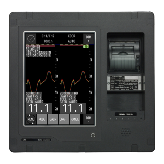
2. Control Panel This section describes the names and functions of the control panel and its controls. The screen shown below is defined as the main screen. Printer Name Plate Buzzer 図2-1 表示処理装置と画面 Figure 2-1 Display processing unit and Main screen Function Switches the equipment power on and off. - Page 30 (Blank page) 2. Control Panel...
-
Page 31: Display Mode
3. Display mode 3.1 Standard mode Standard mode displays real time sounding echoes [Sample screen at single frequency] [Sample screen at dual frequency] Echo drawing area Echo drawing area Echo drawing area Function Description Display mode The current display mode and CH number are displayed. Display time The scroll time of the echo drawing area is displayed. -
Page 32: History Mode
3.2 History mode History mode displays past 3hours, 6 hours, 12 hours, 24hours depth graph and real time sounding. [Sample screen at single frequency] [Sample screen at dual frequency] Echo drawing area Echo drawing area History area History area Function Description Display mode The current display mode and CH number are displayed. -
Page 33: Docking Mode
3.3 Docking mode The docking mode displays depth data bigger. [Sample screen at single frequency] [Sample screen at dual frequency] Function Description Display mode The current display mode is displayed. Date and time Date and time information from GPS are displayed. When not connected, the internal clock will be displayed. - Page 34 (Blank page) 3. Display...
-
Page 35: Operation
4. Operation 4.1 Basic Operation Turning Power ON/OFF ・ To turn on power, press the button. ・ To turn off power, press the button. A confirmation screen whether to turn off the power will be displayed. Touch the ✓ button. Adjusting Control Panel Illumination [DIM+/DIM-] ・... -
Page 36: Gain Control [Gain]
Gain control [GAIN] ・ Gain can be set to 41 stages of 0~40. ・ Touch on main screen. The button color change to green and gain menu is displayed. ・ Auto gain mode or manual gain value is displayed with highlight on main screen when gain menu is displayed. -
Page 37: Selecting Display Mode [Mode]
Selecting Display Mode [MODE] ・ Each time with touch, the display mode changes. Single frequency: Each time with touch, the display mode changes as follows. Standard mode: ↓ History mode: HIST_CH1 ↓ Docking mode: DOCKING ↓ Return to the Standard mode Dual frequency: Each time with touch, the display mode changes as follows. -
Page 38: Displaying Menu [Menu]
Displaying Menu [MENU] Displays the menu for setting various functions. Touch button on the main screen. ・ Each Item are selected by touch. ・ Select the required item to display the setting menu for that item. ・ When it returns to the main screen, touch Up and Down Key Cursor [CURSOR] ... -
Page 39: Right And Left Key Of Cursor [Cursor]
Right and Left Key of Cursor [CURSOR] When it is a history mode ・ When the is touched, a time cursor is moved left, and it moves accelerating when keeping touching it. ・ When the is touched, a time cursor is moved right, and it moves accelerating when keeping touching ・... -
Page 40: Menu List
4.2 Menu List Menu Tree 4. Operation... -
Page 41: Display Setting
4.3 Display Setting , the following menu will be displayed. ◎Touch ・ Select the required item to display the settings. ・ When is touched, return to previous menu ・ When is touched in each sub menu, selected content or setting value is registered in system. -
Page 42: Noise Rejection
Noise Rejection ◎The generation of this noise is decreased when a weak noise to the entire screen occurs and the screen is hard to see. ・ Touch and the settings will be displayed. Set content: 0/1/2/3/4/5/6/7/8/9/10 ・ Touch to increase the value and to decrease it. -
Page 43: Setting Cursor Display
Setting Cursor Display ◎The cursor display method in a standard mode and a history mode is selected. ・ Touch and the settings will be displayed. Set content: OFF/ON/AUTO OFF:The Depth cursor is not always displayed ON: The Depth cursor is always displayed. AUTO:... -
Page 44: Setting Depth Display
Setting Depth Display ◎The standard when the depth value is displayed is selected. ・ Touch and the settings will be displayed. Set content:SURF/KEEL/XDCR SURF:The record and the depth value in which the draft adjusted value is considered are displayed. KEEL:The record and the depth value in which the keel correction value is considered are displayed. -
Page 45: Switching The Display Colors Of The Day And Night Screen
Switching the display colors of the day and night screen ◎Select a setting value to change the display color. ・ Touch and the settings will be displayed. Set content:DAY/DUSK/NIGHT DAY:Set the display color for daytime. DUSK : Set the display color of dim lighting such as early morning or evening. NIGHT:Set the display color scheme for night. -
Page 46: Setting Depth Alert
4.4 Setting Depth Alert , the following menu will be displayed. Depth where the depth alert starts is set. ◎Touch ・ Touch and the settings will be displayed. ・ Change the setting contents by entering a numerical value or ・ Depth can be set up to 99.9m by a 0.1m unit. ・... -
Page 47: Initial Setting
4.5 Initial Setting ・ Touch , the following menu will be displayed. ・ Select the required item to display the settings. ・ When is touched, return to previous menu Change screen color ◎Set the screen color of DAY/DASK/NIGHT ・ Touch and the following menu will be displayed ・... - Page 48 DAY ◎Set the color scheme when [DAY] is selected in the DAY/DUSK/NIGHT settings. ・ Touch and the settings will be displayed. 7color + BLACK: Echo color is 7colors and screen is black. 7color + BLUE: Echo color is 7colors and screen is blue. 7color + WHITE:Echo color is 7colors and screen is white.
-
Page 49: Setting Adjustment Of Date And Time
Setting Adjustment of Date and Time ◎Date/Time/Time difference/GPS synchronization is set. ・ Touch and the following menu will be displayed. ・ Select the required item to display the settings. ・ When is touched, return to previous menu ・ When is touched in each sub menu, selected content or setting value is registered in system. - Page 50 DIFF (Time difference) ・ Touch and the setting will be displayed. ・ The setting items are ± / hour / minute in order from the top of the screen. ・ Touch to increase the value and to decrease it. ・...
-
Page 51: Touch Panel Calibration
GPS SYNC (GPS synchronization) ・ Touch the settings will be displayed. Set content:OFF/ON OFF:An internal clock is used. ON:Uses time information from GPS. Also, when the internal clock of the processing unit deviates by 30 seconds or more, the internal clock is corrected to the time information from GPS. -
Page 52: Printer Control Setting
4.6 Printer Control Setting , the following menu will be displayed. ◎Touch ・ Select the required item to display the settings. ・ When is touched, return to previous menu ・ When is touched in each sub menu, selected content or setting value is registered in system. - Page 53 COPY: A present screen display is printed. The direction of paper feed is length against the screen. HISTORY:All the memorized depth data is graphically printed. The direction of paper feed is time. Secondary data is printed following primary in display screen for dual frequency. On single frequency mode, only displaying frequency data is printed.
- Page 54 2. HISTORY print mode 3. LOG print mode Depth data and graph 4. Operation 4-20...
-
Page 55: Setting Log Book Print
Setting Log Book Print ◎This item selects automatic LOG book print mode. 2021 When select this interval setting menu to 0.5min, 1min, 2min, 5min, 10min, depth data and time will automatically print with every selected interval. When GPS position data is connected, LAT/LON position data would print. ・... -
Page 56: Checking System Version
4.7 Checking system version ◎ Internal software version and DSP version are displayed. ・ Touch and the software and DSP version will be displayed. ・ After confirming, touch 4.8 Initializing menu settings ◎Initialize user settings. ・ Touch and the confirmation screen will be displayed. ・... -
Page 57: Print Out Menu
4.9 Print out menu ◎ The contents are printed according to the printer settings(Refer to 4.6 printer control setting). ・ Touch and the confirmation screen will be displayed. ・ Touch to start printing. ・ Touch to return to the previous screen without printing. 4.10 SELF TEST , the following menu will be displayed. -
Page 58: Demo Mode
Demo Mode ◎ Execute demonstration. ・ Touch and the setting will be displayed. ・ Detail item :OFF/ON ・ Change the settings with , ・ Touch to start demonstration when setting is ON. ・ During demo mode, the "In demo mode" window is displayed. Tap the window to hide it. -
Page 59: Self-Test Of Lcd Unit
Self-test of LCD Unit ◎ Self-testing LCD Unit by displaying color pattern ・ Touch and the confirmation screen will be displayed. ・ Touch to start self-testing. ・ Color pattern(black->red->green->blue->white) is displayed with screenful. *When color pattern display is not correct, contact us or your agency. Self-test of Touch Panel ◎... -
Page 60: Self-Test Of Alert
Self-test of Alert Refer to 4.12 Alert Control for more details on each alert. ◎ Self-testing by simulating each alert. ・ Touch to display the alert for self-test. ・ Select the required item to display the settings. ・ When is touched, return to previous menu ・... - Page 61 Depth Alert ・ Touch and the setting will be displayed. ・ Detail item :OFF/ON ・ Change the settings with , ・ Touch to start simulating alert when setting is ON. * To use this function, it is necessary to turn on the DEPTH ALERT generation setting in the equipment settings.
- Page 62 WEAK ECHO TX A ・ Touch and the setting will be displayed. ・ Detail item :OFF/ON ・ Change the settings with , ・ Touch to start simulating alert when setting is ON. * To use this function, it is necessary to turn on the WEAK ECHO TX:AFT alert generation setting in advance in the equipment settings.
- Page 63 No Paper ・ Touch and the setting will be displayed. ・ Detail item :OFF/ON ・ Change the settings with , ・ Touch to start simulating alert when setting is ON. * To use this function, it is necessary to turn on the NO PAPER alert generation setting in advance in the equipment settings.
-
Page 64: Self-Test Of Buzzer Test
Self-test of Buzzer Test ◎ Self-testing Buzzer. ・ Touch and the confirmation screen will be displayed. ・ Touch to start self-testing. *When buzzer does not sound, contact us or your agency. 4. Operation 4-30... -
Page 65: Self-Test Of Transducer
Self-test of TRANSDUCER Touch to display a menu for selecting CH1 CH2. When select the CH to diagnose, a warning window is displayed. After reading the warning contents, touch to start the self-test. This function cannot completely identify the failure of the transducer. Use this as a guide to see when the transducer is operating normally. -
Page 66: Displaying Of Equip Menu
The sounding function cannot be used and depth data output to other equipment (E.G. ECDIS) is stopped while TRANSDUCER function of self-test is performed. Do not use this function during voyage. Carry out while the ship is moored. 4.11 Displaying of EQUIP menu ◎Touch , the following menu will be displayed. -
Page 67: Alert Control
4.12 Alert Control Over view This section describes the types, displays, and settings of each alert. JFE-400/700 Echo Sounder displays alerts in accordance with IEC62923 Ed.1.0. Alert priority is defined as three types according to its priority and severity as shown in the table below. Priority Description(severity) Display Color... -
Page 68: Alert Icon And Status
The details of each alert are as follows. Name Raising Rectification Support information The water depth becomes the set The water depth becomes DEPTH ALERT Sail toward depth area deeper value of the water depth alert or deeper than the set value of the than current position becomes shallower than that. -
Page 69: Alert Display
Alert Display When an alert occurs, the alert message and icon are displayed at the top of the screen. After that, JFE-400/700 Echo Sounder can be operated by touching the screen as shown in the figure below. ● Alert Massage (ex; Depth Lost) ●... -
Page 70: Alert List Function
● Visual display of alerts Unacknowledged alarm and warning flash on Alert Messages and Alert Details Area. Caution is only lighting. After acknowledged, alarm and warning are lighting. Alert List function The Alert List function can also be selected from the main menu. Touch , the Alert List screen will be displayed. -
Page 71: Connecting With Cam System
Connecting with CAM system Each alert can be displayed on not only own screen but also the CAM system by connecting CAM system. In addition, the following functions can be used by connecting to the CAM system. ● Alert silence from CAM The alert sound ringing on JFE-400/700 Echo Sounder can be silenced by operating on the CAM system. - Page 72 (Blank page) 4. Operation 4-38...
-
Page 73: Maintenance & Check
5. Maintenance & Check Do not open the equipment to inspect or repair internal circuits. Inspection or repairs by anyone other than a specialized technician may result in fire, electrical shock, or malfunction. If internal inspection or repair is necessary, contact our service center or agents. 5.1 Daily Maintenance The life of the equipment depends on the execution situation of the daily maintenance and check. -
Page 74: Maintenance Function
5.3 Maintenance Function Touch Panel Calibration Refer to "Touch Panel Calibration" in 4.5 Initial Setting. Displaying System No. Refer to 4.7 Checking system version. 5.4 Replacing Printer Paper Be careful not to cut your hands with the cutting edge of the paper cutter. Name Model type Remarks... -
Page 75: Troubleshooting
5.5 Troubleshooting The table below shows the principal symptom, the cause, and measurements. As a result, request the repair to our company or our agency when it is not possible to recover to normal operational condition. Symptom Cause Measurements The screen doesn't appear The breaker of AC100-230V of the ship is Make the breaker of AC100-230V of the ship even if power switch is... -
Page 76: Replacing Fuses
5.6 Replacing Fuses Exchange the fuse for the one of our specification. Exchange it after confirming the cause to which the fuse is blown. Moreover, turn off the main switch of the power supply CQD-2348 when you exchange fuses (Press ○ sign side). Model type Rating Remarks... -
Page 77: Consider Installation
6. Consider Installation • Do not install the JFE-700 where subject to the following conditions as such conditions may cause failures and reduce the life of the equipment. 1. Where liable to be splashed with water. 2. Where ventilation is poor. - Page 78 (Blank page) 6. Consider Installation...
-
Page 79: After-Sales Service
Note that such inspection and maintenance is subject to charge. Please consult JRC or its agent for further details of any part of the after service conditions. Contact: See at end of manual. -
Page 80: Warranty & After-Sales Service
If any failure occurs in the product during its normal operation in accordance with the instruction manual, the dealer or JRC will repair free of charge. In case that any failure is caused due to misuse, faulty operation, negligence or force major such as natural disaster and fire, the product will be repaired with charges. -
Page 81: Disposal
When this equipment is to be disposed, please follow the guidelines of the local body governing the location at which the equipment is disposed of. 8.2 Chinese Version RoHS 有毒有害物质或元素的名称及含量 (Names & Content of toxic and hazardous substances or elements) 形式名(Type): JFE-700 名称(Name): Echo Sounder 有毒有害物质或元素 (Toxic and Hazardous Substances and Elements) 部件名称... - Page 82 (Blank page) 8. Disposal...
-
Page 83: Specifications
Power fail alert, Depth alert, System alert: (Relay contact output: rated load 120VAC 10A, 30VDC 8A, NO/NC) Specification:IEC61162-450 Transmission speed:10/100Mbps Data input/output :NMEA,IEC,JRC format IGMP snooping: IGMP v1, IGMPv2, IGMP v3 Temperature –15°C to +55°C / operating –25°C to +70°C / storage Humidity less than 93%RH under +40°C condition (non-condensing) - Page 84 (Blank page) 9. Specification...
-
Page 85: Appendix
10. Appendix 10.1 Echo sample Noise Bubble Noise Bubble Interruption Interference Noise from other ship Plankton layer 10. Appendix 10-1... - Page 86 Actual Pictures Zero line DISP TRANS figure A Seabed DISP SURF DISP KEEL Seabed Zero line Third reflection of bottom Second reflection of bottom Seabed In case of a shallow seabed or when increasing the amplifier sensitivity, two seabed lines may be recorded.
- Page 87 Seabed Quality Change Rock In case of a hard seabed composed of rocks etc., its return trails long, as shown in right chart. In case of a soft seabed made of mud, seaweed, etc., they poorly reflect an ultrasonic wave to result in thin recording of the seabed with short trail.
- Page 88 In case of flat seabed, thin second return of seabed may sometimes appear, which is slightly below the actual seabed. In either case, the dim or thin echoes are false and produced by side lobes of ultrasonic beam from the transducer. Any false echo is thinner than and parallel to a real echo. The echo of a seabed with abrupt slope is recorded as a lone difficult to see and less discriminative, since it tends to accompany with a false echo due to the side lobe and the inherent property of directivity.
-
Page 89: Data Format
10.2 Data Format 1.List of Handling Sentence Data Sentence Description Message Type Direction Interface Depth Output LAN & Serial Depth below transducer Output LAN & Serial Depth below keel Output LAN & Serial Depth below surface Output LAN & Serial PJRCU Depth relative to transducer Output... - Page 90 2: Water depth, meters 3: Water depth, fathoms 4) DBS – Depth below surface $--DBS, x.x, f, x.x, M, x.x, F*hh<CR><LF> 1: Water depth, feet 2: Water depth, meters 3: Water depth, fathoms 5) PJRCU – Depth relative to transducer (2frequencies) $PJRCU,SD,x.x,x.x,x.x,x.x,xx,c-c*hh<CR><LF>...
- Page 91 These cannot be null fields. 2) The sequential message identifier relates all sentences that belong to a group of multiple sentences (i.e.message). Multiple sentences with the same sequential message identifier, make up onemessage. 3) Contains the number of alert entries transported within this sentence. 4) Alert entry 0 –...
- Page 92 Standard (IMO MSC.302(87)): A, Category A: Alerts where information at operator unit directly assigned to the function generating the alert is necessary, as decision support for the evaluation of the alert-related condition, e.g. graphical information of danger of collision or graphical information of danger of grounding.
- Page 93 12) This field is used for Alert title which is mandatory and for additional alert description which is optional. • The first ALF sentence transmits the Alert title. Alert title is maximum 16 characters short form of the alert text. •...
- Page 94 responsibility transfer: O silence: S 10) HBT – Heartbeat supervision sentence $--HBT,x.x,A,x*hh<CR><LF> 1 2 3 1: Configured repeat interval 1) 2: Equipment status 2) 3: Sequential sentence identifier 3) Note; 1) Configured autonomous repeat interval in seconds. This field should be set to NULL in response to a query if the query response feature is supported.
- Page 95 2) Equipment in normal operation A = yes, V = no This field can be used to indicate the current equipment status. This could be the result of an built-in integrity testing function. 3) The sequential sentence identifier provides a message identification number from 0 to 9 that is sequentially assigned and is incremented for each new sentence.
- Page 96 high speed craft. C = Caution when integrity is not available. U = Unsafe when the estimated positioning accuracy (95 % confidence) is less than the selected accuracy level corresponding to the actual navigation mode, and/or integrity is available but exceeds the requirements for the actual navigation mode, and/or a new valid position has not been calculated within 1 s for a conventional craft and 0,5 s for a high speed craft.V = Navigational status not valid, equipment is not providing navigational status indication.
- Page 97 1) Positioning system mode indicator: D = Differential S = Simulator N = Data not valid 2) The mode indicator field supplements the status field (field 6). The status field should be set to V = invalid for all values of operating mode except for A = Autonomous and D = Differential. The positioning system mode indicator and status fields should not be null fields.
- Page 98 described in equipment standards. Number range 10000-9999999 is reserved for proprietary alerts and number ‘0’ is reserved for a command request to all alerts (e.g. alert command Q requests transmission of all alert states). Alert Identifier examples: “001”, “2456789”, “245” 4) The alert instance identifies the current instance of an alert to distinguish alerts of the same type (Alert identifier) and from the same source (e.g.
- Page 100 Not use the asbestos For further information,contact: URL Head office : http://www.jrc.co.jp/eng/ Marine Service Department 1-7-32 Tatsumi, Koto-ku, Tokyo 135-0053, Japan : tmsc@jrc.co.jp e - mail : +81-50-3786-9201 One - call ISO 9001, ISO 14001 Certified CODE No.7ZPNA2081 JUN. 2021 Edition 4...
Need help?
Do you have a question about the JFE-700 and is the answer not in the manual?
Questions and answers