Table of Contents
Advertisement
Quick Links
Advertisement
Table of Contents

Related Manuals for JRC JHS-180


Summary of Contents for JRC JHS-180
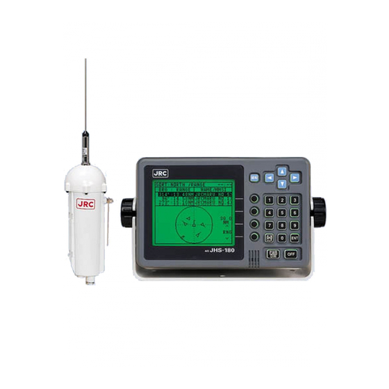
- Page 1 Automatic Identification System JHS-180 Instruction Manual 7ZPJD0173A...
- Page 3 Preface Thank you for purchasing JHS-180 Automatic Identification System. JHS-180 is the Class A shipborne equipment of the universal Automatic Identification System. • Be sure to read this manual for full comprehension before using the equipment. • Save this manual near at hand for quick reference in the future.
-
Page 4: Before Operation
Before Operation Concerning the symbols This manual uses the following symbols to explain correct operation and to prevent injury or damage to property. The symbols and descriptions are as follows. Understand them before proceeding with this manual. WARNING Indicates a warning that, if ignored, may result in serious injury or even death. -
Page 5: Handling Precautions
Handling Precautions WARNING Do not disassemble or customize this unit. Doing so may cause fire, electrical shock or malfunction. Do not use a voltage other than specified. Doing so may cause fire, electrical shock or malfunction. Do not touch any parts where this warning label is pasted. Doing so may cause electrical shock. - Page 6 Handling Precautions CAUTION Do not use this equipment for anything other than specified. Doing so may cause malfunction or damage to persons. Do not turn the trimmer resistors or the trimmer capacitors on the PCB unit, except when and if they need to be adjusted. Doing so may cause malfunction or damage to persons.
-
Page 7: External Views
External Views NTE-180 AIS Transponder NCM-722 AIS Controller... - Page 8 NQD-4190 Junction Box NQE-3111 Connection Box...
- Page 9 NBD-577A Power Supply Unit...
-
Page 10: Table Of Contents
CONTENTS Preface ........................i Before Operation .....................ii Handling Precautions .....................iii CAUTIONS AGAINST HIGH VOLTAGE ..............v Cautions concerning treatment of electrocution victims ........v First aid ........................vi External Views .......................ix CONTENTS ......................xiii Abbreviations ......................xv 1.GENERAL ..................1.1 Outlines ..................... 1-1 1.2 Features .................... - Page 11 5.3.2.2 Waypoint Text ..................5-18 5.3.2.3 Estimated Time of Arrival (ETA) ............5-19 5.3.2.4 Waypoints ....................5-20 5.3.3 Navigation Information Setting ..............5-21 5.3.3.1 Navigational Status Information ............5-21 5.3.3.2 Persons On-Board ................5-21 5.3.3.3 Type of Ship and Cargo Type ..............5-22 5.3.3.4 Draught....................5-23 5.3.3.5 Height Over Keel .................5-23 5.3.4 Alarm Setting ....................5-24 5.3.4.1 Range ....................5-24 5.3.4.2 Lost Target ...................5-24...
-
Page 13: General
● Increased Probability of Vessel Detection ━━━━━━━━━━━━━━━━━━━━━━━━━━━━━━━━━━━━━━━━━━━ JHS-180 is equipped with a guard zone alert function. When preset guard zone range and other vessel enters into the zone, JHS-180 indicates and sounds the alert. This function enhances probability of vessel detection. -
Page 14: Components
Components 1. 3. 1 Standard Components Name Type Quantity Remarks AIS Transponder NTE-180 With 2m cable, Fitting belts AIS Controller NCM-722 Power Supply Cable 7ZCJD0095 L=5m Control Cable 1 7ZCAF0078 L=5m Junction Box NQD-4190 Connection Box NQE-3111 Power Supply Unit NBD-577A Spare Parts 7ZXJD0027... -
Page 15: Configration
Configuration • System Block Diagram... - Page 16 • Outline Drawing of NTE-180 AIS Transponder ━━━━━━━━━━━━━━━━━━━━━━━━━━━━━━━━━━━━━━━━━━━ Unit: mm Mass: approx. 3.3 kg...
- Page 17 • Outline Drawing of NQD-4190 Junction Box ━━━━━━━━━━━━━━━━━━━━━━━━━━━━━━━━━━━━━━━━━━━ Unit: mm Mass: approx. 1.2 kg...
- Page 18 • Outline Drawing of NCM-722 AIS Controller ━━━━━━━━━━━━━━━━━━━━━━━━━━━━━━━━━━━━━━━━━━━ Unit: mm Mass: approx. 2.0 kg...
- Page 19 • Outline Drawing of NQE-3111 Connection Box ━━━━━━━━━━━━━━━━━━━━━━━━━━━━━━━━━━━━━━━━━━━ Unit: mm Mass: approx. 5.5 kg...
- Page 20 • Outline Drawing of NBD-577A Power Supply ━━━━━━━━━━━━━━━━━━━━━━━━━━━━━━━━━━━━━━━━━━━ Unit: mm Mass: approx. 10.0 kg...
-
Page 21: Installationdiagram
2. INSTALLATION DIAGRAM Notes: Leave installation of this equipment to our service center or agents. Installation by an unauthorized person may results in malfunction. -
Page 23: Part Names And Functions
3. PART NAMES AND FUNCTIONS (1) LCD Panel (2) Menu key (3) Arrow Keys (4) Numerical Keys (5) Enter key (6) Alarm off /CLR key (7) Select-1 key (8) Select-2,3,4 (9) Power/Dimmer key (10) Power OFF key keys (1) LCD Panel For further information, refer to “4. -
Page 25: Displays
4. DISPLAYS Display Title Current time Minimum other ships list (three) Other ships list, Other ship’s detail information Menu for operation Status display line for alarm and message reception... -
Page 27: Operation
5. OPERATION Menu Tree Select(1) key (Power On) [▲]/[▼],[ENT] Other Ship's detail Information Other Ships List [0]-[9] or [▲]/[▼],[ENT] [0]-[9] or [▲]/[▼],[ENT] [0]-[9] or [▲]/[▼],[ENT] [MENU] [MENU]key 3.MAIN MENU 1.MESSAGE 1.EDIT AND TX Destination address Message type Message editing Transmission 2.TX TRAY Transmitted Message reading 3.RX TRAY... -
Page 28: Basic Operation
Basic Operation 5.2.1 Turning the power ON Press [PWR/DIM] for 1 second to turn ON the power, then “Other Ships List” appears. 5.2.1.1 Other Ships List Other ship’s information • Bearing • Range • Ship’s name Selected ship ∗ “ “... - Page 29 5.2.1.2 Other Ship’s Detail Information Ship’s detail information can be displayed by pressing the [ENT] when the other ships list displays. Pressing upward arrow key displays previous page of the ship’s detail information. Pressing this select key returns to “Other ships list”. Pressing this select key displays “Edit and TX”.
-
Page 30: Turning The Power Off
5.2.2 Turning the power OFF Turning the power OFF needs inputting the password. Pressing [OFF] displays “Shut-down” to input the password. After inputting the password, pressing and holding [PWR/DIM] and [OFF] for one second turns the power OFF. Refer to “5.3.6.1 Password Setting” to change the password. -
Page 31: Alarm
5.2.3 Alarm 5.2.3.1 Guard zone alarm When other ship comes in own guard zone ring, the alarm status display “GD ZONE” appears and alarm tone sounds. The display of the alarm ship’s line is reversal. Pressing [ALM/CLR] turns off the alarm tone. 5.2.3.2 Lost target alarm When other ship loses in lost target ring, the alarm status display “LOST”... -
Page 32: Main Menu
5.3 Main Menu “Main Menu” can display by pressing [MENU] in any operation. MAIN MENU UTC11:43 BRG : RANGE NAME/MMSI 270°: 0.18NM JRC MARU1 35°: 0.29NM JRC MARU2 ○ Pressing this select key returns “Other ships list”. 22°: 0.92NM JRC MARU1 1.MESSAGE 2.DESTINATION ○ 3.NAVIGATION 4.ALARM SETTING 5.GROUP SHIP ○ 6.SET UP 7.MAINTENANCE ○ Pressing up-arrow key or down-arrow key selects the menu. Pressing [ENT] displays the selected menu display. -
Page 33: Message Menu
5.3.1 Message Menu “Message Menu” can be displayed by pressing the [1] in the “Main Menu”. (“Message Menu”) MESSAGE MENU UTC11:43 BRG : RANGE NAME/MMSI 270°: 0.18NM JRC MARU1 Pressing this select key returns “Other ships 35°: 0.29NM JRC MARU2 ○... -
Page 34: Edit And Tx
5.3.1.1 Edit and TX “Edit and TX” (MMSI, Type and Form) can be displayed by pressing the [1l in the “Message Menu”. The cursor appears in the “MMSI” field when “Edit and TX” display is opened. (MMSI, Type and Form) @... - Page 35 (Message editor) EDIT AND TX UTC11:43 BRG : RANGE NAME/MMSI 270°: 0.18NM JRC MARU1 Pressing this select key returns “Other ships list”. 35°: 0.29NM JRC MARU2 ○ 22°: 0.92NM JRC MARU1 MAYDAY! MAYDAY! A ○ Pressing this select key returns to previous menu. (“Message Menu”, “TX Tray”, “RX Tray” or “Other Ship’s detail EXIT> ○...
-
Page 36: Tx Tray
5.3.1.2 TX Tray “TX Tray”(Message List) can be displayed by pressing [2] in “Message Menu”. When “BROADCAST”, “OK”: transmission success or “NG”: transmission failure is displayed. When “MMSI”(addressed message), ”AK”: Acknowledge received or “NK”: Acknowledge not received is displays. (Message List) TX... - Page 37 (Not Transmitted Message Read) TX MESSAGE READ UTC11:43 BRG : RANGE NAME/MMSI 270°: 0.18NM JRC MARU1 ○ 35°: 0.29NM JRC MARU2 22°: 0.92NM JRC MARU1 MAYDAY! MAYDAY! Pressing this select key transmits the message. ○ TX> Pressing this select key returns “TX Tray” ○...
-
Page 38: Rx Tray
5.3.1.3 RX Tray “RX Tray”(Message List) can be displayed by pressing [3] in “Message Menu”. (Message List) RX TRAY UTC11:43 BRG : RANGE NAME/MMSI 270°: 0.18NM JRC MARU1 Pressing this select key returns “Other ships list”. 35°: 0.29NM JRC MARU2 ○ 22°: 0.92NM JRC MARU1 CATEGORY FROM *ROUT 777777777 EDIT> ○ Pressing this select key displays “Edit and TX”. *SAFE AK 999999999 &TX... - Page 39 5.3.1.4 Interrogation “Interrogation” can be displayed by pressing [4] in “Message Menu”. INTERROGATION UTC11:43 BRG : RANGE NAME/MMSI 270°: 0.18NM JRC MARU1 Pressing this select key returns “Other ships list”. ○ 35°: 0.29NM JRC MARU2 22°: 0.92NM JRC MARU1 1.DEST1 MMSI:77777777 No.1 Destination REQ1-1:POSITION REPORT(A) ○ REQ1-2:STATIC & VOYAGE(A) No.1 Interrogation detail 2.DEST2 MMSI:888888888 ○ REQ2-1:NAVIGATION TO AIDS No.2 Destination ○...
-
Page 40: Interrogation
(Interrogation and Acknowledgment) INTERROGATE ACK UTC11:43 BRG : RANGE NAME/MMSI 270°: 0.18NM JRC MARU1 35°: 0.29NM JRC MARU2 ○ Pressing this select key returns “Other ships list”. 22°: 0.92NM JRC MARU1 WAITING 1.ACK1 OK CHECK> ○ Pressing this select key displays the acknowledgment detail. 2.ACK2 NONE ○ EXIT> ○ Pressing this select returns “INTERROGATION”. Pressing [ALM/CLR] returns “INTERROGATION”. (Example as Acknowledgment Detail) POSITION... -
Page 41: Long Range Message
5.3.1.5 Long Range Message “Long Range Message” can be displayed by pressing [5] in “Message Menu”. LONG RANGE UTC11:43 BRG : RANGE NAME/MMSI 270°: 0.18NM JRC MARU1 Last received message from the Long range 35°: 0.29NM JRC MARU2 ○ 22°: 0.92NM JRC MARU1 Last transmitted message to the Long range ○ ○ Pressing this select key starts the message ○... -
Page 42: Destination Setting
5.3.2 Destination Setting “Destination” Setting menu can be displayed by pressing [2] in the “Main Menu”. (“Destination” Setting menu) DESTINATION UTC11 : 43 BRG : RANGE NAME/MMSI 270°: 0.18NM JRC MARU1 Pressing this select key returns “Other ships 35°: 0.29NM JRC MARU2 ○... -
Page 43: Destination
5.3.2.1 Destination “Destination” name can be inputted by pressing [1] in the “Destination” Setting menu. (Selecting “Destination” name) DESTINATION UTC11 : 43 BRG : RANGE NAME/MMSI 270°: 0.18NM JRC MARU1 Pressing this select key returns “Other ships 35°: 0.29NM JRC MARU2 ○ list”. 22°: 0.92NM JRC MARU1 Pressing this select key opens the keypad to 1.DESTINATION... -
Page 44: Waypoint Text
5.3.2.2 Waypoint Text “Waypoint Text” can be inputted by pressing [2] in the “Destination” Setting menu. DESTINATION UTC11:43 BRG : RANGE NAME/MMSI 270°: 0.18NM JRC MARU1 35°: 0.29NM JRC MARU2 ○ 22°: 0.92NM JRC MARU1 1.DESTINATION ○ TOKYO 2.WAYPOINT TEXT ABCDEFGHIJKLMNOPQRST ○ 3.ETA 2001/02/08 07:07 ↑ ABCDEFGHIJKLM↑↓ HH:MM Pressing this select key closes the keypad and ... -
Page 45: Estimated Time Of Arrival (Eta)
5.3.2.3 Estimated Time of Arrival (ETA) Estimated Time of Arrival (ETA) can be inputted by pressing [3] in the “Destination” Setting menu. DESTINATION UTC11 : 43 BRG : RANGE NAME/MMSI 270°: 0.18NM JRC MARU1 35°: 0.29NM JRC MARU2 ○ 22°: 0.92NM JRC MARU1 1.DESTINATION ○ TOKYO 3.WAYPOINT TEXT ABCDEFGHIJKLMNOPQRST ○ 3.ETA 2010/02/08 07:07 (UTC YYYY/MM/DD HH:MM)... -
Page 46: Waypoints
5.3.2.4 Waypoints “Waypoint” can be displayed by pressing [4] in the “Destination” Setting menu. Fourteen waypoints can be set as maximum. Twenty letters can be set as waypoint name. Waypoint List WAYPOINTS UTC11 : 43 BRG : RANGE NAME/MMSI 270°: 0.18NM JRC MARU1 ○ 35°: 0.29NM JRC MARU2 22°: 0.92NM JRC MARU1 1. N 36°50 110 ... -
Page 47: Navigation Information Setting
5.3.3 Navigation Information Setting “Navigation Information Setting” menu can be displayed by pressing [3] in the “Main Menu”. (“Navigation Information Setting” menu) NAVIGATION UTC11:43 BRG : RANGE NAME/MMSI 270°: 0.18NM JRC MARU1 35°: 0.29NM JRC MARU2 ○ 22°: 0.92NM JRC MARU1 1.NAVIGATIOAL STATUS UNDER WAY USING ENGIN ○ 2.NUMBER ON-BOARD 8191 3.TYPE OF SHIP PASSENGER SHIP ○ 4.CARGO TYPE ALL SHIPS OF THIS TYP 5.DRAUGHT 10.0m ○ 6.HEIGHT OVER KEEL 204.7m Pressing up-arrow key or down-arrow key selects the sub menu. -
Page 48: Type Of Ship And Cargo Type
5.3.3.3 Type of Ship and Cargo Type The cursor appears in the “Type of Ship”/“Cargo Type”. Pressing up-arrow key or down-arrow key selects the setting of “Type of Ship”/ “Cargo Type”. Pressing [ALM/CLR] quits the selecting and returns to “Navigation Information Setting” menu. Pressing [ENT] entries the selected detail and returns to “Navigation Information Setting”... -
Page 49: Draught
5.3.3.4 Draught The cursor appears in the “Draught”. Pressing numerical key inputs the value of “Draught”. The value can be set “25.5m” as maximum. Pressing [ALM/CLR] quits the inputting and returns to “Navigation Information Setting” menu. Pressing [ENT] entries the inputted value and returns to “Navigation Information Setting” menu. 5.3.3.5 Height Over Keel The cursor appears in the “Height Over Keel”. -
Page 50: Alarm Setting
5.3.4 Alarm Setting “Alarm Setting” menu can be displayed by pressing [4] in the “Main Menu”. (“Alarm Setting” menu) ALARM SETTING UTC11:43 BRG : RANGE NAME/MMSI 270°: 0.18NM JRC MARU1 35°: 0.29NM JRC MARU2 ○ 22°: 0.92NM JRC MARU1 1.RANGE 10.0NM... -
Page 51: Group Ship Setting
5.3.5 Group Ship Setting “Group Ship List” can be displayed by pressing [5] in the “Main Menu”. Ten MMSI can be registered for own group as maximum. (“Group Ship List”) GROUP SHIP LIST UTC11:43 BRG : RANGE NAME/MMSI 270°: 0.18NM JRC MARU1 35°: 0.29NM JRC MARU2 ○ 22°: 0.92NM JRC MARU1 NAME MMSI Pressing this select key inserts a new ship‘s NIHONMARU1 431000001... -
Page 52: Setup Menu
5.3.6 Setup menu “Setup” menu can be displayed by pressing [6] in the “Main Menu”. (“Set up” menu) SETUP UTC11:43 BRG : RANGE NAME/MMSI 270°: 0.18NM JRC MARU1 35°: 0.29NM JRC MARU2 ○ 22°: 0.92NM JRC MARU1 1.PASSWORD ○ 2.CH MANAGEMENT 2.OWN SHIP DATA 4.MESSAGE RESPONSE ○ 5.CONTRAST 6.NUMBER OF RETRIES: 3 ○ Pressing up-arrow key or down-arrow key selects the sub menu. Pressing [ENT] opens the selected sub menu display. -
Page 53: Password Setting
5.3.6.1 Password Setting “Password” setting menu can be displayed by pressing [1] in the “Setup” menu. (“Password” setting menu) PASSWORD UTC11:43 BRG : RANGE NAME/MMSI 270°: 0.18NM JRC MARU1 35°: 0.29NM JRC MARU2 ○ 22°: 0.92NM JRC MARU1 1.PASSWORD **** ○... -
Page 54: Channel Management Setting
5.3.6.2 Channel Management Setting “Channel Management” setting menu can be displayed by pressing [2] in the “Set Up” menu. Eight channel management settings can be memorized in the transponder as maximum. (“Channel Management” setting menu) CH MANAGEMENT UTC11:43 BRG : RANGE NAME/MMSI 270°: 0.18NM JRC MARU1 35°: 0.29NM JRC MARU2 ○ 22°: 0.92NM JRC MARU1... - Page 55 “TX Power” The cursor appears in the “TX Power” field. Pressing up-arrow key or down-arrow key inputs the “TX power” detail from “High” or “Low” Pressing [ALM/CLR] quits the inputting and returns to the “Channel Management” setting menu. Pressing [ENT] entries the inputted detail and returns to the “Channel Management” setting menu.
- Page 56 (2) Check and Set the Channel Management The inputted Channel Management detail has to be registered to the transponder for channel management operation. Pressing the “[Check]” select key checks whether or not the inputted detail can be set to the transponder, and display “OK”...
- Page 57 (3) Channel Management list Display and Confirm the registered Channel Management detail list from the transponder to input manually the channel management detail. Pressing the “[List]” select key displays the channel management setting of the transponder. (Channel Management List) CH MANAGE LIST UTC11:43 BRG : RANGE NAME/MMSI...
-
Page 58: Own Ship Data Display Setting
5.3.6.3 Own Ship Data display setting “Own Ship Data” display setting menu can be displayed by pressing [3] in the “Set Up” menu. (“Own Ship Data” display setting menu) OWN SHIP DATA UTC11:43 BRG : RANGE NAME/MMSI 270°: 0.18NM JRC MARU1 35°: 0.29NM JRC MARU2 ○ 22°: 0.92NM JRC MARU1 Pressing this select key switches the setting of OWN SHIP DATA ON CHANGE>... -
Page 59: Contrast Setting
5.3.6.5 Contrast setting “Contrast” setting menu can be displayed by pressing [5] in the “Set Up” menu. (“Contrast” setting menu) CONTRAST UTC11:43 BRG : RANGE NAME/MMSI 270°: 0.18NM JRC MARU1 35°: 0.29NM JRC MARU2 ○ 22°: 0.92NM JRC MARU1 CONTRAST: 4... -
Page 60: Maintenance Menu
5.3.7 Maintenance menu “Maintenance” menu can be displayed by pressing [7] in the “Main Menu”. (“Maintenance” menu) MAINTENANCE UTC11:43 BRG : RANGE NAME/MMSI 270°: 0.18NM JRC MARU1 35°: 0.29NM JRC MARU2 ○ 22°: 0.92NM JRC MARU1 1.TRX CONDITION ○ 2.AIS ALARM 3.SENSOR... -
Page 61: Trx Condition Log Display
5.3.7.1 TRX Condition log display “TRX Condition” log display can be displayed by pressing [1] in the “Maintenance” menu. Latest condition is displayed as “1” (Operating condition). (“TRX Condition” log display) TRX CONDITION UTC11:43 BRG : RANGE NAME/MMSI 270°: 0.18NM JRC MARU1 35°: 0.29NM JRC MARU2 ○ 22°: 0.92NM JRC MARU1 “Channel A and B” number 1.CH A:2087 DEFAULT TX/RX... -
Page 62: Ais Alarm Display
5.3.7.2 AIS Alarm display “AIS Alarm” display can be displayed by pressing [2] in the “Maintenance” menu. Latest alarm status is displayed. (“AIS Alarm ” display) A I S A L A R M U T C 1 1:4 3 ... -
Page 63: Power On/Off Log Display
5.3.7.4 Power On/Off Log display “Power On/Off Log” display can be displayed by pressing [4] in the “Maintenance” menu. (“Power On/Off Log” display) POWER ON/OFF LOG UTC11:43 BRG : RANGE NAME/MMSI 270°: 0.18NM JRC MARU1 35°: 0.29NM JRC MARU2 ○ 22°: 0.92NM JRC MARU1 ON 2010/02/02 10:00:59 OFF 2010/02/02 09:00:59 ○ ON 2010/02/02 08:00:59 OFF 2010/02/02 07:00:59 ○ ○ Pressing up-arrow key or down-arrow key scrolls the display. Pressing [ALM/CLR] returns to “Maintenance”... -
Page 65: Maintenance And Inspection
6. MAINTENANCE AND INSPECTION The performance and longevity of this equipment depend on careful maintenance. To maintain the best performance, the following periodic inspections are highly recommended. (1) Keep the power supply voltage within the specified value. (2) Know the condition of normal status when the equipment is properly functioning. Keep comparing the current status to the normal status to immediately detect any malfunctions. -
Page 67: After-Sales Service
7. AFTER-SALES SERVICE Before returning repair If what appears to be a defect is detected, refer to “6.3 Troubleshooting” to check if the equipment is actually defective before requesting repair. If the defect persists, immediately stop operation and call our service center or agents. During the warranty period, we or our agencies (*1) will repair the malfunction without any fee, according to the specified procedure. -
Page 69: Specifications
8. SPECIFICATIONS 8.1 AIS TRANSPONDER (NTE-180) (1) Frequency range : 156.025MHz to 162.025MHz, : Default channels:161.975MHz, 162.025MHz (2) Channel spacing : 25kHz/12.5kHz : Within ±3×10 (3) Frequency accuracy (4) Type of emission : F1D, F2B (5) Type of modulation : GMSK, FSK (6) Output power : 12.5W/2W (7) Rated power supply voltage... - Page 70 Note: IEC61162-2 interfaces comply with the following specifications. - Output drive capacity: Differential driver output voltage is 2.0V or more (RL=100 ohms), Driver output current 50mA - Load on the line of inputs: 100 ohms. 1 IEC61162-1 output can drive 1 IEC61162-2 input. - Electrical isolation of input circuits: Input circuits are electrically isolated from internal circuit with opto-isolator.
- Page 72 For further information contact: HEAD OFFICE & Akasaka Twin Tower (Main), 17-22, Akasaka 2-chome, Minato-ku, SALES DEPT. Tokyo 107-8432 JAPAN Phone : +81-3-3584-8711 : +81-3-3584-8715 Telex : 0242-5420 JRCTOK J MAIN PLANT 1- 1, Shimorenjaku 5-chome, Mitaka-shi, Tokyo 181-8510 JAPAN Phone : +81-422-45-9111 : +81-422-45-9110 Telex : 02822-351 JRCMTK J...
Need help?
Do you have a question about the JHS-180 and is the answer not in the manual?
Questions and answers