Table of Contents
Advertisement
Quick Links
Advertisement
Table of Contents

Related Manuals for JRC JFE-582


Summary of Contents for JRC JFE-582
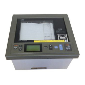
- Page 1 Echo Sounder JFE-582/585 Service Manual...
-
Page 3: Table Of Contents
Contents 1. Specification 2. Components 3. Construction 4. Installing the Recorder Unit 5. Installing the Transducer 6. Connecting Components 7. Schematic Diagram 8. Electrical Parts Layout 9. Mechanical Parts List 10. Replacing Consumables 11. Maintenance and Inspection 12. Mater Reset 13. -
Page 53: Description Of Working And Parts List
JFE-582 / 585 DESCRIPTION OF WORKING PARTS LIST... - Page 55 1-3. Inside the transducer consists of element like condenser, and insulation resistance of its core cable is infinity. (∞) 2.MATCHING BOX AW-154F 2-1. This box included matching transformer is installed between JFE-582 (RECORDER) and TRANSDUCER to match cable loss. 3.RECORDER JFE-582 3-1.
- Page 56 3-2-3. When carried out self-test (NMEA Loop Test), No.6 and No.7 Depth Data on Terminal TB502 have to be connected to No.1 and No.2 position on Terminal TB501;otherwise, NG will be indicated. 3-3. CBD-1488 POWER UNIT 3-3-1. To input Ships power supply voltage between AC85 and A265V and provide DC+140V of transmitting High voltage, and 12V of common voltage for IC circuit.
- Page 57 Parts List NAME TYPE CODE 200K TX/RX UNIT CML-596-2 CML-596-2 (JFE-582) 200kHz 50K TX/RX UNIT CML-596-5 CML-596-5 (JFE-585) 50kHz I/O UNIT CQD-1705 CQD-1705 JFE-582 POWER UNIT CBD-1488 CBD-1488 (JFE-585) PANEL UNIT CCK-831 CCK-831 RECORDER TRIGGER UNIT CPA-132B CPA-132B PEN BELT MOTOR...
-
Page 59: Check Sheet For General Checking
JFE-582 / 585 CHECK SHEET GENERAL CHECKING... - Page 61 Check Sheet for Echo Sounder Japan Radio co.,Ltd HOW MANY TRANSDUCERS? ONLY ONE WHICH TRANSDUCER IS ABNORMAL? BOTH VISUAL INSPECTION WHAT KIND OF SYMPTOM? DOES A "SEABED" IMAGE RECORDING ON PAPER? DIGITAL "DEPTH" INDICATION ON LCD? INDICATE THE FOLLOWING? RECO RD ING PAPER TIM E M A RK ZERO LINE M ARK LIN E...
- Page 62 ROM VERSION CML-596-2 TX/RX UNIT (This type only for JFE-582 200kHz) CO-R1.O2 CML-596-5 TX/RX UNIT (This type only for JFE-585 50kHz) CO-R1.O2SP0 VERSION NO. TRANSMITTING WAVE CHECK ON "TB201" TERMINAL NO.1 AND 3 CML-596-2 TX/RX UNIT (JFE-582 200kHz) 900VP-P CML-596-5 TX/RX UNIT...
- Page 63 Remove the following all transducer cables. Terminal of Echo sounder, Matching (Junction) Box, Remove cable Remove cable JFE-582 (585) Junction Box Transducer Measure the following core cables by the insulation resistance meter (DC500V). White and black, white and screen, black and screen.
- Page 64 Not tuning Output Voltage 1 to 1.5Vp-p Frequency JFE-582 200kHz±5kHz JFE-585 50kHz±1kHz Tuning point Normal tuning frequency range JFE-582 200kHz ± 5kHz JFE-585 50kHz ± 1kHz Vp-p↑ fo = → f JFE-582 fo =200kHz±5kHz JFE-585 fo = 50kHz±1kHz If the result of the measurement is except for the above range then transducer defective...
- Page 65 Check on junction box. AW-154F-(50) Remove the following all transducer cables. Terminal of Echo sounder, Matching (Junction) Box, AW-154F (AW-154F-50) Remove cable JFE-582 (585) Junction Box Transducer Measure the following core cables by transducer checker. JFE-582 200kHz Zo= 120 ± 80Ω Ω...
-
Page 67: The First Aid For Transducer Problem
JFE-582 / 585 THE FIRST AID TRANSDUCER PROBLEM... - Page 69 Inner Hull installation for Echo Sounder’s transducer The temporary modification when damaged transducer of the Echo Sounder. TRANSDUCER 1. The installation method of transducer to the ship's bottom. 2. For safety; Open the manhole on before 24-hour work start, and remove the poisonous gas.
- Page 70 ECHO SOUNDER FITTING ON INNER HULL. This photograph for JFE-582 (200kHz) Photograph 1 The digital display is none only in the time mark and the oscillation line recording on paper. Photograph 2 Transducer tank...
- Page 71 Check the following item of the old cable before connect it. *Insulation resistance . *The breakage of the cable . Photograph 3 Old Transducer cable Transducer cable connection part Waterproof processing execution ending Photograph 4 Position where Transducer is installed inner Hull...
- Page 72 Check it after about 24 hours after the above working end. Silicone rubber is necessary to fix for 24 hours. Material to prepare ITEM TYPE JRC CODE Transducer for JFE-582 UT-200ND20 (200kHz) 6UNBS00285 JFE-585 UT-50MD-20 (50kHz) 5UNAB00025 -------------------------------------------------------------------------------------------------------- Silicone rubber ex.KE-45-W SHINETSU...
-
Page 73: In Case Of Other Problem
JFE-582 / 585 IN CASE OTHER PROBLEMS... - Page 75 In case of “Date & Time” is no print out. The order of priority of the NMEA sentence of this Echo Sounder is the following. 1st. GGA GGA-Global positioning system ( GPS )fix data Time,position and fix-releted data for a GPS receiver. $---GGA,hhmmss.ss,llll.ll,a,x,xx,x.x,M,x.x,M,x.x,xxxx*hh<CR><LF>...
- Page 77 OPTION NWW-58 REMORTE DISPLAY...
- Page 79 NWW−58 NWW−58 Remote Display Remote Display NWW−58 NWW−58 Remote Display Remote Display Operating Controls ③ ② ① Name Function Panel Dimmer Set panel dimmer level with the adjust dial. ① LCD Contrast Set LCD contrast level with the adjust dial. ② Adjust Level Adjust level.
- Page 80 REMOTE DISPLAY NWW-58 In case of panel and LCD dimmer are dark. 1. Internal dimmer Cut and short the resistor. 2. External dimmr...
-
Page 83: Inspection After Work
INSPECTION AFTER WORK Japan Radio co.,Lt INDICATE THE FOLLOWING ON THE RECORDING PAPER? RECO RD ING PAPER TIM E M A RK ZERO LINE M ARK LIN E SEA BED (BO TTO M ) INDICATE THE FOLLOWING LINE? TIME MARK ZERO LINE SEABED (BOTTOM LINE) MARK LINE (WHEN PUSH THE "MARK"... - Page 85 GRASPING OF THE CONDITION!!! The confirmation of the condition is important for the repair of Echo Sounder Let's send attached "ASKS ABOUT THE CONDITION OF ECHO SOUNDER" to the ship directly, and get reliable information.
- Page 86 ASKS ABOUT THE CONDITION OF ECHO SOUNDER Japan Radio co.,Ltd WHICH TRANSDUCER IS ABNORMAL? BOTH WHAT KIND OF SYMPTOM? DOES A "SEABED" IMAGE RECORDING ON PAPER? DIGITAL "DEPTH" INDICATION ON LCD? INDICATE THE FOLLOWING? RECO RD ING PAPER TIM E M A RK ZERO LINE M ARK LIN E SEA BED (BO TTO M )
-
Page 87: Technical Information
JFE-582 / 585 TECHNICAL INFORMATION... - Page 89 : company secret Technical information transaction up to agency open Issue Number 02BSCN0002 Order of priority □A:reform immediately Date June 24, 2002 Model JFE-585 □B:Improve with regular check or visiting Equipment Echo sounder □C:Improve with customer’s request Section in charge Navigation &...
- Page 90 Procedure sheet to change ROM IC page 1 of 3 Procedure 1. Open the front panel of echo sounder and mechanical block. (photo. 1, 2) 2. Turn off the main switch on the power supply unit. (photo. 4) 3. Remove the ROM IC (version CO-R1.02) on the TX/RX unit. (photo. 5) 4.
- Page 91 Procedure sheet to change ROM IC page 2 of 3 Photo. 4 Turn off main switch Photo. 5 Remove the ROM IC On the power supply unit Lift the IC from both Press “O” mark side side Photo. 6 Insert new ROM IC version CO-R.02SP0 Note: 1 New IC’s pins are spread.
- Page 92 Procedure sheet to change ROM IC page 3 of 3 Photo. 7 Turn on the main switch Photo. 8 safety door-switch Press “—“ mark side The lever of door-switch * Take care for not losing this lever. Photo. 9 LCD display on normal opening...
- Page 94 JFE-582 / 585 ECHO SOUNDER SERVICE MANUAL...
Need help?
Do you have a question about the JFE-582 and is the answer not in the manual?
Questions and answers