JRC JAN-7202 Instruction Manual
Bridge alert management system
Hide thumbs
Also See for JAN-7202:
- Installation manual (100 pages) ,
- Instruction manual (332 pages) ,
- Field service manual (1078 pages)
Table of Contents
Advertisement
JAN-7202/9202
Bridge Alert
Management System
(BAMS)
Instruction Manual
System Overview
Name and Function of Each Unit
Bridge Alert Management (BAM)
Failure Mode and Effects Analysis (FMEA)
Maintenance & Inspection
Alert Icon List
Menu List and Materials
1
2
3
4
5
APP A
APP B
8
9
10
11
12
13
14
15
16
17
18
19
20
21
22
23
24
Advertisement
Table of Contents

Related Manuals for JRC JAN-7202


Summary of Contents for JRC JAN-7202
- Page 1 System Overview Name and Function of Each Unit Bridge Alert Management (BAM) Failure Mode and Effects Analysis (FMEA) Maintenance & Inspection APP A Alert Icon List JAN-7202/9202 APP B Menu List and Materials Bridge Alert Management System (BAMS) Instruction Manual...
-
Page 3: Table Of Contents
Contents Section 1 System Overview ................1-1 Functions ..........................1-1 Features ..........................1-1 Components .......................... 1-2 General System Diagrams (Example) .................. 1-3 Section 2 Name and Function of Each Unit ............2-1 Name and Main Function of the Operation Unit ..............2-1 2.1.1 Trackball operation unit .................... - Page 4 3.1.4 State of alerts ........................ 3-3 3.1.5 Display sequence according to the alert status ............3-4 3.1.6 About alert management screen ................... 3-4 3.1.7 Alert acknowledgment locations and buzzer sound emission locations ....... 3-5 Alert Management Screen ....................3-6 3.2.1 Alert management screen .....................
- Page 5 FMEA Check Sheet ....................... 4-1 Section 5 Maintenance & Inspection ..............5-1 Updating Help Data ....................... 5-1 Appendix A Alert List ..................A-1 Appendix B Menu List and Materials ............... B-1 Menu List ..........................B-1 B.1.1 Alert ..........................B-1 B.1.2 Settings .........................
- Page 6 Contents...
-
Page 7: Section 1 System Overview
Section 1 System Overview Functions BAMS (Bridge Alert Management System), which enables quick understanding of the status in the bridge by intensively displaying alerts that occurred in bridge based on the concept of BAM, supports the improvement of the safe transportation and work efficiency. BAMS has the following functions •... -
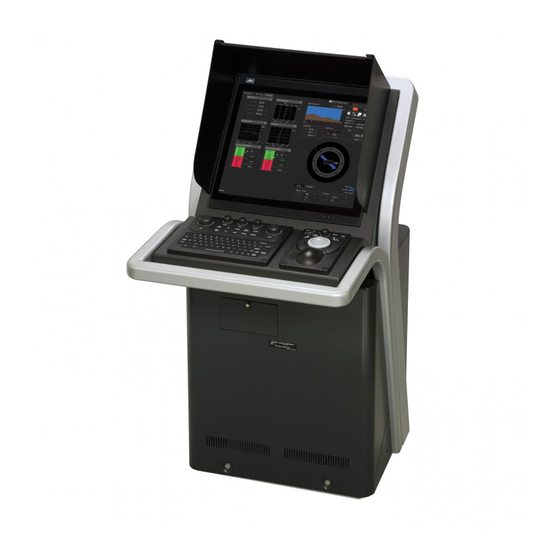
Page 8: Components
Components A list of system components is shown below. Name Model Q’ty Remarks Conning (Main unit) JAN-7202/JAN-9202 Display (JAN-7202) NWZ-207 (JAN-9202) NWZ-208 Trackball operation unit NCE-5605 Keyboard operation unit NCE-5625 Central control unit NDC-1590 Power supply unit NBD-913 Junction Box... -
Page 9: General System Diagrams (Example)
General System Diagrams (Example) 付録 Section 1 System Overview... - Page 10 Section 1 System Overview...
-
Page 11: Section 2 Name And Function Of Each Unit
Section 2 Name and Function of Each Unit Name and Main Function of the Operation Unit 2.1.1 Trackball operation unit (10) When turning off the power supply, do not press the Power button on the operation unit for an extended period of time. If the button is pressed for an extended period of time, the equipment may not be terminated normally, causing a failure. - Page 12 Name Function outline Power button Use this button to turn on and off this equipment. [MULTI] dial - Turn this dial to operate the function that is assigned to the [MULTI] dial, such as the Display Brightness function. - If the [MULTI] dial is held down, the Display Brightness function is assigned to the [MULTI] dial forcibly.
-
Page 13: Keyboard Operation Unit (Option)
2.1.2 Keyboard operation unit (Option) (7) (8) (14) (15) (10) (13) (11) (12) (16) Name Function outline [EBL] dial No use. [VRM] dial No use. [RAIN] dial No use. [SEA] dial No use. [GAIN] dial No use. [TX STBY] key No use. - Page 14 Name Function outline [USER2] key - Executes the function that is assigned to the key. - When this key is held down, the setting dialog box of the function that is assigned to the [USER2] key appears. Keyboard The keyboard is used for the input of numeric values and characters at operation of this equipment.
-
Page 15: 2.1.3 Display Unit
2.1.3 Display unit [Brightness Adjustment] [Power] button buttons [Power] button When the Power button is pressed while the power of the display unit is turned off, the power is turned on. To turn off the power of the display unit, press the Power button for 5 seconds or longer. [Brightness Adjustment] buttons These buttons are used to adjust the brightness of the screen. -
Page 16: Names And Main Functions Of The Task Screen Common Sections
Names and Main Functions of the Task Screen Common Sections This section describes the names of task screen common sections and outlines the main functions on the alert management screen and the Conning Display. Assignment function name Right toolbar area [Menu] button Display Example of the Alert Management Screen Assignment function name... - Page 17 Key assignment indication area When the [MULTI] dial is turned, the assigned functions are operated. Right toolbar The functions of the buttons on the right toolbar are as follows. Day/Night button Display Brightness button The display color on the screen can be Adjust the screen brightness within the range of 0 to switched to 5 levels according to the 100.
-
Page 18: Switching The Day/Night Mode
2.2.1 Switching the Day/Night mode The screen display color can be switched to any of five levels according to the brightness in the bridge. Use the following procedure for switching. Click on the Day/Night button on the right toolbar. Adjustment buttons are displayed based on the brightness that is currently set. Example: Day2 is set. -
Page 19: Adjusting The Brightness Of The Screen And Operation Unit
2.2.2 Adjusting the brightness of the screen and operation unit 2.2.2.1 Adjusting the Brightness of the Screen The screen brightness can be adjusted within the range from 0 to 100. Click on the [Display Brightness] button on the right toolbar. The following screen brightness buttons are displayed. -
Page 20: Adjusting The Brightness Of The Operation Unit
2.2.2.2 Adjusting the Brightness of the Operation Unit The brightness of the operation section can be adjusted in 5 levels (0 to 4). Click on the [Panel Brightness] (Brightness of the operation unit) on the Right Tool Bar. The following operation unit brightness buttons are displayed. Adjust the brighness by using the [Light] button and [Dark] button. - Page 21 In order to set an offset value so that the light emitted becomes the same as in other equipment when it is set to the same value as the screen brightness of other equipment, click the "Advanced" (advanced adjustment)button and adjust the offset value using the buttons displayed for setting the "Offset".
-
Page 22: Common Basic Operations
Common Basic Operations 2.3.1 Powering on and starting Turn on the power supply according to the following procedure. For low-temperature start-up, perform pre-heat for more than 30 minutes. Otherwise, an operation failure and an accident may occur. Press the Power button on the operation unit. The Power button is lit and the start-up screen is displayed. -
Page 23: Basic Operation When Using A Trackball
2.3.3 Basic operation when using a trackball A trackball in the trackball operation unit is mainly used for the operations of this equipment. This section describes the basic operations performed using the trackball. 2.3.3.1 Trackball functions Trackball Left button Right button Trackball: Use the trackball to move the cursor on the screen. -
Page 24: Basic Click Operations
2.3.3.3 Basic click operations When the cursor is set to a button and the button is clicked on, the function of the selected button is executed. • When a function On/Off button is clicked on, the setting is switched to On/Off each time. •... -
Page 25: Closing The Menu
A submenu is displayed depending on the function. In this case, display a dialog box of the function by clicking on the button on the submenu. Example: Maintenance Menu Maintenance submenu 2.3.4.2 Closing the menu Click on the [X] button on the menu (submenu). 2.3.5 Basic dialog box operations When the dialog is opened, the setting contents of the dialog are those set at the factory delivery or... -
Page 26: Closing The Dialog Box
2.3.5.2 Closing the dialog box Close the dialog by clicking on the [X] button of the dialog. [x] button 2.3.6 Managing Files with File Manager The file manager function enables the copying of route files and user map from the hard disk of this equipment to external storage media such as DVD or from external storage media to the hard disk of this equipment. -
Page 27: File Management
2.3.6.2 File management The "File Management" tab enables file management. File management copies files between SSD of this equipment and external storage media and deletes files. This section describes file management by using the example copying a file in the file list of the drive that is specified in the [Drive] list on the left hand side of the dialog box to the drive that is specified in the [Drive] list on the right hand side. - Page 28 The following file types can be displayed by the file manager. File type File extension Contents Screen Shot (AUTO) Automatically generated screen shot Screen Shot (User) Manually generated screen shot Select the files to be copied by checking them. Select a drive of the storage destination from the [Drive] combo box and select a copy location from the folder tree that is displayed.
- Page 29 Click on the [Copy>>] (copy to the right) button. The files are copied. When the drive of the copy source and the drive of the copy destination are reversed, click on the [<<Copy] (copy to the left) in Step 5. Deleting a file Click on the [Delete] button.
- Page 30 Section 2 Name and Function of Each Unit 2-20...
-
Page 31: Section 3 Bridge Alert Management (Bam)
Section 3 Bridge Alert Management (BAM) Outline 3.1.1 About BAM The BAM harmonizes the priority, classification, handling, distribution and presentation of alerts, to enable the bridge team to devote full attention to the safe operation of the ship and to immediately identify any alert situation requiring action to maintain the safe operation of the ship. -
Page 32: Categories Of Alerts
3.1.3 Categories of alerts Alerts should be separated for the alert handling into three categories of alerts. Categories Description Category A Category A alerts are specified as alerts where information at a task station directly assigned to the function generating the alert is necessary, as decision support for the evaluation of the alert-related condition, e.g.: •... -
Page 33: State Of Alerts
3.1.4 State of alerts Alert State Description Emergency (Active) Notified by lighting or blinking the icon on the alarms screen. A buzzer sound is not emitted. Cleared when the alert cause is resolved. Alarms Unacknowledged/raised alarm Notified by blinking the icon on the screen and emitting a buzzer sound. -
Page 34: Display Sequence According To The Alert Status
3.1.5 Display sequence according to the alert status Active alerts are displayed in the active alert list in the following sequence according to the alert status. (The following alerts are displayed in the descending order.) • Emergency alarm • Unacknowledged/raised alarm •... -
Page 35: Alert Acknowledgment Locations And Buzzer Sound Emission Locations
3.1.7 Alert acknowledgment locations and buzzer sound emission locations The following table shows the locations where alerts can be acknowledged and the locations from which an buzzer sound is emitted. Please refer to “Appendix A List of Alert Icons” for the icon. Section 3 Bridge Alert Management (BAM) -
Page 36: Alert Management Screen
Alert Management Screen Alert management screen provides central management of the alert which occurred on the bridge. In order to display the alert management screen, select "Alert Management" by the change of a mode. The alert management screen provides active alert display, alert list information and alert history display. -
Page 37: Active Alert] Tab
[Alert History] tab Refer to "3.2.1.3 [Alert History] tab". Approvable Alert Information Status icon Alert cause Equipment name Among the unacknowledged alerts of category B, the alert information of the highest priority is displayed. When the alert is an alarm or warning, a status icon flashes. When there is no target alert, "No Acknowledgeable Alert"... - Page 38 [1] Active alert information The quantity of current occurring alerts is displayed. Quantity of active alerts Quantity of unacknowledged alerts When the quantity of alarms is 100 or more, "More" is displayed instead of the count. [2] Active page information Up to 20 alert information items can be displayed in one page.
- Page 39 • The raised alerts are displayed. When any of the alerts are clicked on, the alert is selected. • The details of the selected alert are displayed in "[5] Active alert details". • If a new alert occurs when alerts are sorted and displayed by priority on the screen, it will be added to the top position of the corresponding priority.
- Page 40 [5] Details of active alert The detailed information of the alert being selected in the active alert list is displayed. The displayed contents of the detailed information vary with the alert being selected. Two types of alerts are available, individual alerts and aggregated alerts. An individual alert occurs due to a single cause while an aggregate alert is displayed by aggregating individual alerts of the same type.
- Page 41 Item Detailed information Equipment Displays the equipment where the alert is generated. Cause Displays the cause of the alert. Raised Displays the alert generation time. Details Displays the details of the cause of the alert. Advice Displays the action to take. Acknowledged Displays the time when the alert was acknowledged.
- Page 42 Name of aggregated alert Displays the name of the aggregated alert. Individual alert list of aggregated alert Displays the list of alerts that have occurred. If any of alerts is clicked, the detailed information of that alert is displayed in the detailed alert information area. Detailed alert information Item Description of Display...
-
Page 43: Alert List] Tab
3.2.1.2 [Alert List] tab On the screen of the [Alert List] tab, the equipment names and all the alerts that occurred from each equipment (including normal states) are displayed. All the alerts defined are displayed in a list for each piece of equipment. Alerts concerning MFD are selected according the license. - Page 44 [3] Active alert information The quantity of current occurring alerts is displayed. Quantity of active alerts Quantity of unacknowledged alerts When the quantity of alarms is 100 or more, "More" is displayed instead of the count. [4] [ACK this page](Collective acknowledgment) button This button acknowledges all the alerts (excluding alarms of Category A and Category C) in the page that is currently displayed.
- Page 45 [7] Equipment name list Equipment names are displayed. When an equipment name is clicked on, the alert list of the equipment is displayed. • In the initial state, equipment names are displayed alphabetically in the ascending order. [8] Alert status icon This icon indicates the corresponding alert status.
-
Page 46: Alert History] Tab
3.2.1.3 [Alert History] tab In the [Alert History] tab, a list of past alerts that have been rectified is displayed. Inhibit target alert An alert that is not activated even if it occurred is called an Inhibit target alert. An Inhibit target alert is specified by the BAM file and is ignored even if it occurs. The alert is not displayed on the [Alert History] tab screen. - Page 47 [2] Alert History list • Rectified alerts are displayed. When any of the alerts is clicked on, the alert is selected (enclosed by a blue frame). • The details of the selected alerts are displayed in "(3) Details of alert history". •...
- Page 48 [5] Alert search Alerts in the alert history list can be searched by specifying a condition. For the search operation, refer to "Searching alerts". Searching alerts Search filter combo box Search Word input box [Next] (Search next) button [Previous] (Search previous) button Select a search target on the Search Filter combo box.
- Page 49 [6] [Export] button Press this button to export alert history information to the USB memory in CSV format. The following information items are written to the CSV file for one alert. Source / Cause / Category / Current Priority / Original Priority / Raised / Acknowledged / Rectified / Details / Comment Up to 5000 alerts can be exported.
-
Page 50: Conning Display Screen
3.2.2 Conning Display screen This section describes the names and main functions of each section of the Conning Display screen. For the information other than active alerts and acknowledgeable alert of Conning Display, refer to the "Conning Display" instruction manual. Section 3 Bridge Alert Management (BAM) 3-20... - Page 51 [1] Active Alert Active alert Active alert information information Page information Page information The alert cause and the equipment name switch at a regular interval. Active alert list Active alert list [List/Detail] button [List/Detail] button [Raised] button [Raised] button [Priority] button [Priority] button Active Alert Information The quantities of alerts that are currently occurring are displayed.
- Page 52 Active alert list • The alerts that are currently raised are displayed. When any of the alerts is clicked on, the alert is selected. • When the [List/Detail] button is clicked on the selected alert, the details are displayed. For the details, refer to "[List/Detail] button".
- Page 53 • In the case of individual alerts The following screen appears if an individual alert is being selected in the active alert list. Active alert detail display [List/Detail] button Active alert detail display Detail information of the selected alerts is displayed. Item Detailed information Equipment...
- Page 54 [List/Detail] button When this button is clicked on, the display is switched to the list display. • In the case of aggregated alerts The following screen appears if an aggregated alert is being selected in the active alert list. (For more information about aggregated alerts, refer to "3.3.6.6 Aggregated alerts".) Name of aggregated alert Individual alert list of aggregated alert Detailed alert information...
- Page 55 Detailed alert information Item Description of Display Equipment Displays the name of the unit in which the alert has occurred. Cause Displays the alert cause. Raised Displays the time when the alert has occurred. Details Displays the detailed alert cause. Advice Displays the action to take.
-
Page 56: Confirming And Acknowledging An Alert
Confirming and Acknowledging an Alert When an alert is generated, a buzzer sound is emitted, and the alert contents are displayed on the screen of the [Active Alert] tab. The general procedure for handling an alert is shown below. [Category-A Alert] [Category-B Alert] Alert generation Alert generation... -
Page 57: Stopping The Buzzer
[Category-C Alert] Alert generation Stop the buzzer "3.3.1 Stopping the buzzer" Check the alert contents "3.3.2 Confirming alert contents" Acknowledge the alert "3.3.5 Acknowledging the alert (CAT-C)" Rectify the alert cause 3.3.1 Stopping the buzzer To stop a buzzer (silencing), click the silence button or press the [SILENCE] key in the trackball operation unit. -
Page 58: Confirming Alert Contents
3.3.2 Confirming alert contents When an alert is generated, the alert message is displayed in the "Active Alert tab". 3.3.3 Acknowledging the alert (CAT-A) The Alarm of category-A cannot be acknowledged in alert management screen. It is necessary to acknowledge this alarm at the generated equipment. 3.3.4 Acknowledging the alert (CAT-B) After checking the alert contents, when the [ACK] button of the active alert list or [ACK] button of the... -
Page 59: Flow Of Alart Silence And Acknowledgement Operations
3.3.6 Flow of alart silence and acknowledgement operations 3.3.6.1 Silence and acknowledgment operations on the occurrence source equipment In CAM, buzzer sound Alert 1 is not emitted for Category A alerts. Alert 1 Alert 1 Alert 1 Alert 1 Alert 1 3-29 Section 3 Bridge Alert Management (BAM) -
Page 60: Silence And Acknowledgement Operations On Cam
3.3.6.2 Silence and acknowledgement operations on CAM In CAM, buzzer sound Alert 1 is not emitted for Category A alerts. Alert 1 Alert 1 Alert 1 Alert 1 Alert 1 Section 3 Bridge Alert Management (BAM) 3-30... -
Page 61: Silence And Acknowledgment Of The Alerts That Are Notified At Dry Points
3.3.6.3 Silence and acknowledgment of the alerts that are notified at dry points In CAM, buzzer sound Alert 1 is not emitted for Category A alerts. Alert 1 Alert 1 Alert 1 Memo • The alert acknowledgement operation in the occurrence source equipment is allowed under category A/B/C. -
Page 62: Silence Operation At The Occurrence Of Alerts From Multiple Equipment Units
3.3.6.4 Silence operation at the occurrence of alerts from multiple equipment units Silence operation in CAM In CAM, buzzer sound Alert is not emitted for Category A alerts. Alert Silence operation in the occurrence source equipment In CAM, buzzer sound is Alert Alert not emitted for Category... -
Page 63: Acknowledgment Operation At The Occurrence Of Alerts From Multiple Equipment Units
3.3.6.5 Acknowledgment operation at the occurrence of alerts from multiple equipment units Acknowledgment operation in CAM (category B alerts only) In CAM, buzzer sound Alert Alert is not emitted for Category A alerts. Alert Alert Acknowledgment operation in the occurrence source equipment In CAM, buzzer sound is Alert Alert... -
Page 64: Aggregated Alerts
3.3.6.6 Aggregated alerts Alerts of the same type may be grouped and displayed as one alert. These alerts are referred to as Aggregated alerts (CPA/TPA alert and so on). An aggregated alert is indicated by a status icon with "+" symbol. Target 1 CPA/TCPA occurred... -
Page 65: Redundancy Concept
Redundancy Concept The concept of backup and redundancy is as follows. 1) Two units featuring CAM are installed in the system. One unit displays the alert management screen in the normal state and functions as the alert management server (hereinafter referred to as the CAM (Main)). - Page 66 Display Memo As the backup equipment of CAM, Ack/silence the following JRC equipment units UI function are necessary with the license that Alert indication mode activation Alert CONNING Alert authorization. information Management function function - JAN-7201/9201 ECDIS - JAN-7202/9202 Conning Display...
-
Page 67: Transfer Of Alert To Bnwas
Transfer of Alert to BNWAS When a BNWAS (Bridge Navigational Watch Alarm System) is connected, specify the time to transfer an unacknowledged alert to the BNWAS in a range between 0 and 30 seconds. (Refer to "3.7.2 Setting up alert processing") 3-37 Section 3 Bridge Alert Management (BAM) -
Page 68: Monitoring The Ias Status
Monitoring the IAS status The IAS status can be monitored with CAM for the ship with IAS (Integrated Automation System) installed. 3.6.1 Displaying IAS alerts Alerts from IAS are displayed on the alert management screens of CAM ([Active Alert] tab screen and [Alert History] tab screen). -
Page 69: Setting Up Alerts
Setting Up Alerts This section explains a setup of alert processing operations, and a setup of alert timer using the [Alert] menu. 3.7.1 Selecting setting items When the [Alert] menu is opened, the "Alert" dialog box appears. By selecting a setting item in the "Alert" dialog box, the setting dialog of the selected item can be displayed. -
Page 70: Setting Up Alert Processing
The following items can be set in the "Alert" dialog box. item contents Function restriction Set the actions to be taken at the next stage for None an unacknowledged alert. Refer to "3.7.2 Setting up alert processing". 3.7.2 Setting up alert processing When [AMS] is selected in the Classification pane, the "AMS"... - Page 71 Item Contents Remarks Repetition of Set a time interval for an unacknowledged alert with warning Default: 60 s UNACK priority to re-emit a warning sound within the range from 0 to 300 Warning seconds. A warning sound is repeatedly emitted for this alert until it is acknowledged.
-
Page 72: Setting Up The Operation Mode
Setting Up the Operation Mode 3.8.1 Basic operation of the "Settings" dialog box You can set up the operation mode in the "Settings" dialog box. Click on the [Menu] button in the lower left corner of the screen. The menu is displayed. Click on the [Settings] button. -
Page 73: Setting Color And Brightness
3.8.2 Setting color and brightness Set the color and brightness of the display contents. [1] [Def.] (Default value) button When this button is clicked on, all the setting items of the mode that is selected on the [Day/Night] combo box are reset to the Default values. Setting Item Description of Setting Setting Value... - Page 74 Setting Item Description of Setting Setting Value [Brightness] tab Character Set up the text brightness. Level1 [Default of Day3] Level2 [Default of Day2/Dusk /Night] Level3 [Default of Day1] Level4 Panel Set the brightness of the operation unit. Level1(Dark) [Default of Dusk/Night] Level2 [Default of Day3] Level3 [Default of Day2] Level4(Light)
-
Page 75: Setting Sounds
3.8.3 Setting sounds Set the volumes of the operation sounds and error sounds and alert melody. When the volume or melody is to be changed, the volume can be set while listening to the sound since the selected volume or melody is played back. Setting Item Description of Setting Setting Value... - Page 76 Setting Item Description of Setting Setting Value Alert Setting Set up the volume of alert condition not set Reminder notification sound. Level1(Soft) Level2 Level3[Default] Level4(Loud) Navigation 1 Alarm Set up the volume of navigation alarm Level4(Loud)[Default] sound. Navigation 2 Alarm Navigation 3 Alarm CPA/TCPA Alarm Set up the volume of CPA/TCPA alarm...
-
Page 77: Setting Key Assignment
3.8.4 Setting key assignment Only those items of the functions that can be specified in the task dialog are displayed. The [User Keys] tab is displayed only when the optional operation unit is installed. Setting Item Description of Setting Setting Value [User Keys]tab User Key 1 Select a function to assign to the USER1 key... -
Page 78: Checking The Software Information
Checking the Software Information The information of this software can be displayed as follows. Click the [Menu] button in the lower left corner of the screen. The menu appears. Click [Maintenance] - [System Information] on the menu. The "System Information" dialog box appears. Click the [Software] tab. -
Page 79: Section 4 Failure Mode And Effects Analysis (Fmea)
Section 4 Failure Mode and Effects Analysis (FMEA) Extent of Effect, Likelihood of Occurrence, and Level of Criticality Extent of Effect A fire, explosion, a collision, stranding, or other serious phenomena Complete failure of a system or equipment Partial failure of a system or equipment Failure which can be disregarded Failure Probability Generates 1 time or more per month. - Page 80 Section 4 Failure Mode and Effects Analysis (FMEA)
- Page 81 Section 4 Failure Mode and Effects Analysis (FMEA)
- Page 82 Section 4 Failure Mode and Effects Analysis (FMEA)
- Page 83 Section 4 Failure Mode and Effects Analysis (FMEA)
- Page 84 Section 4 Failure Mode and Effects Analysis (FMEA)
- Page 85 Section 4 Failure Mode and Effects Analysis (FMEA)
- Page 86 Section 4 Failure Mode and Effects Analysis (FMEA)
- Page 87 Section 4 Failure Mode and Effects Analysis (FMEA)
- Page 88 Section 4 Failure Mode and Effects Analysis (FMEA) 4-10...
- Page 89 4-11 Section 4 Failure Mode and Effects Analysis (FMEA)
- Page 90 Section 4 Failure Mode and Effects Analysis (FMEA) 4-12...
- Page 91 4-13 Section 4 Failure Mode and Effects Analysis (FMEA)
- Page 92 Section 4 Failure Mode and Effects Analysis (FMEA) 4-14...
- Page 93 4-15 Section 4 Failure Mode and Effects Analysis (FMEA)
- Page 94 Section 4 Failure Mode and Effects Analysis (FMEA) 4-16...
-
Page 95: Section 5 Maintenance & Inspection
Section 5 Maintenance & Inspection Updating Help Data This section describes updating of help data of this product. Note • Help data is classified to the data for RADAR, data for ECDIS, data for Conning Display, and data for AMS. To display help information on each of the RADAR screen, ECDIS screen, Conning Display screen, and AMS screen (Alart management screen), install the help data for each display. - Page 96 A file selection dialog is displayed. [Drive] combo box Folder tree File list Select the drive containing update data from the [Drive] combo box. Select the folder containing update data from the folder tree and check the file to be updated from the file list.
- Page 97 When installation is completed, the following screen is displayed. Click the [OK] button. Memo • When the [Cancel] button is clicked during installation, installation of subsequent files is cancelled after the installation of the file that is currently being installed is completed. •...
- Page 98 Section 5 Maintenance & Inspection...
-
Page 99: Appendix A Alert List
Appendix A Alert List A.1 Caution Indicates a list of alerts with priority caution. Only alerts that are frequently used indicated because there are many alerts. APP A Message Subject Explanation Category No.1 Radar(Alert Communication BAMS Alert sentence of No.1 RADAR Failed) cannot be received. - Page 100 A.2 List of Alert icons The alert icons displayed in the alert status area are listed below. Alert Name of alert icon Functional outline icon For the details, refer to "Emergency Alarm types and emergency alarm display". Active – A flashing red triangle. unacknowledged A symbol of loudspeaker in the middle of the triangle.
- Page 101 Alert Name of alert icon Functional outline icon A plus sign. To be presented together with icons number 2 to 12 Aggregation APP A A red triangle with a cross in the middle of equilateral triangle. Acknowledge not To be presented together with icons number 2, 3 and 6 allowed for alarm A yellowish orange circle with a cross in the middle of circle.
- Page 102 Appendix A Alert List...
-
Page 103: Appendix B Menu List And Materials
Appendix B Menu List and Materials Menu List This section shows the menus and dialog items of this equipment by target menu. * Items that are enclosed by a frame of broken lines indicate the dialog and window names that are displayed by selecting the relevant menu. -
Page 104: Settings
B.1.2 Settings Color and Brightness Day/Night Def. Display Color tab Dialog Character Brightness tab Character Panel Day1 : Level4 / Day2 : Level3 / Day3 : Level2 / Dusk,Night : Level1 Display <26 inch>[0~100]Day1/Day2/Day3 : 67 / Dusk : 60 / Night : 11 <19 inch>... -
Page 105: Maintenance
B.1.3 Maintenance Date/Time/Time Zone (Date) Month Year Time(LMT) Time Zone Display Style Synchronise with Time Source(Date/Time) Synchronise with Time Source(Time Zone) System Information APP B Software tab Type Application Maintenance No. TXRX Presentation Library BAMS Save to USB Device Operating Time (Operating Time of Work Station) Total SSD1... - Page 106 Selftest Monitor Test All Red All Green All Blue All White Pattern4 Pattern5 Pattern6 Gray Scale S-57 Color Pattern ARCS Color Pattern Key Test Key Test Start APP B Key Test Stop Sound Test Sound Test Start Light Test Light Test Start Memory Check Memory Check Start Results...
-
Page 107: Help
B.1.4 Help ← → Home (Contents tab) (Search tab) keyword Search Results APP B APP B APP C Appendix B Menu List and Materials... -
Page 108: Code Input
B.1.5 Code input Password Appendix B Menu List and Materials... -
Page 109: Service
Equipment No. 5 Task Station 6 Equipment No. 6 Task Station 7 Equipment No. 7 Task Station 8 Equipment No. 8 RADAR 1 RADAR 2 VDR(JRC) Printer Heading Sensor 1 Heading Sensor 1(Type) APP C Appendix B Menu List and Materials... - Page 110 Heading Sensor 2 Heading Sensor 2(Type) Log 1 Log 1 Interface/Type Log 2 Log 2 Interface/Type GPS 1 GPS 2 GPS 3 GPS 4 Ship’s Clock Echo Sounder (T/D 1) Echo Sounder (T/D 1) Position Echo Sounder (T/D 2) Echo Sounder (T/D 2) Position Echo Sounder (T/D 3) Echo Sounder (T/D 3) Position NAVTEX...
- Page 111 Serial Port (CCU) Gyro/Log/GPS/AIS Sensor Diagnosis Detail "Serial Port-Detail" dialog box Monitor "Serial Port-Monitor" dialog box ISW/MTR/Serial OPU Diagnosis Monitor "Serial Port-Monitor" dialog box SLC1(M) tab CH1 ~ CH8 CH9 ~ CH10 APP B Gyro I/F Sensor Diagnosis Detail "Serial Port-Detail" dialog box Monitor "Serial Port-Monitor"...
- Page 112 Data Output (Menu for person in charge of installation) (TT) (AIS) Remote Maintenance GPS Select Log Select Navigation Data Channel(1) Detail(1) → "Data Output-Detail" dialog Navigation Data Channel(2) Detail(2) → "Data Output-Detail" dialog Navigation Data Channel(3) Detail(3) → "Data Output-Detail" dialog Navigation Data Channel(4) Detail(4) →...
- Page 113 Settings Alert (Watch Alarm) Reset Interval Trackball Threshold Sound Output Mode AC Power Failure Auto Shutdown of Task Station after (LCD Control) Power Off Set display brightness Power Off of Antenna Interswitch APP B ISW Install (Connection Permission) Display Unit Antenna No.1∼Antenna No.8 Master Antenna No.1∼Antenna No.8 Slave Simple-ISW TXRX Power Supply...
- Page 114 Maintenance Storage Management Drive Information File Information Operating Time Setup (Operating Time of Work Station) Total Clear Clear LCD FAN Clear CCU FAN Clear PSU FAN Clear (Setup of UPS) Setup Date(UTC) Calendar Icon Replace Time Initialization Set Default (All settings except service) Set Default (Service settings) Appendix B Menu List and Materials B-12...
-
Page 115: Lists Of Terminologies, Units, And Abbreviations
Lists of Terminologies, Units, and Abbreviations Abbreviation Term A/D = AD Analog/ Digital A/P = AP Auto Pilot APP B Alternating Current Actual Course Change ACCA Actual Course Change Alarm Acknowledge Acquire, Acquisition Activate After Admiralty Information Overlay (additional information to the navigation) Automatic Identification System Alert LAN Converter APP B... - Page 116 Abbreviation Term C UP Course Up CA-CFAR Cell Averaging CFAR Cargo.Cat Cargo Category CCRP Consistent Common Reference Point CCRS Consistent Common Reference System Central Control Unit Counterclockwise CFAR Constant False Alarm Rate Channel Change Conning Information Display Companion MPU Interface Clear Course Over the Ground Communication Port...
- Page 117 Abbreviation Term Digital Signal Processor Electronic Bearing Line Early Course Change ECDIS Electronic Chart Display and Information System Edition APP B Enhanced Group Calling Electronic Navigational Chart Enhance End of Track Estimated Position Electronic Plotting Aids EPFS Electronic Position Fixing System EQUIP Equipment Estimated Time of Arrival...
- Page 118 Abbreviation Term I/F = IF Interface Input/Output IALA International Association of Marine Aids to Navigation and Lighthouse Authorities IALA-A IALA - Region A IALA-B IALA - Region B Identification International Maritime Organization Indication INFO Information INIT Initialisation Integrated Bridge System Interval IP Address Internet Protocol Address...
- Page 119 Abbreviation Term Microphone Middle Minimum MMSI Maritime Mobile Services Identity Number Man Overboard Monitor APP B Medium Pulse Maritime Safety Committee Message N UP North Up NAV = NAVI Navigation NAVTEX Navigational Telex North East Non Follow Up Not Less Than NMEA National Marine Electronics Association APP B...
- Page 120 Abbreviation Term Relative RADAR Radio Detecting and Ranging RAND Random RCID Raster Chart Issue Date Reference Relative Rev. Revolution Radar I/F Circuit Rhumb Line Relative Motion RM(R) Relative Motion. Relative Trails. RM(T) Relative Motion. True Trails. Root Mean Square Raster Navigational Chart Range RoRo Roll On/ Roll Off (Vessel)
- Page 121 Abbreviation Term Serial LAN Converter Speed Over the Ground Short Pulse Speed SprsLvl Spurious Level Solid State Drive APP B Security Scheme Error Solid State Radar Safety Switch STAB Stabilized, Stabilization STBD Starboard, Starboard Side Sensitivity Time Control Standard Speed Through the Water Surf Surface SW HUB...
- Page 122 Abbreviation Term UNACK Un-Acknowledge Up.No. Update Number Universal Serial Bus Coordinated Universal Time Video VDIN Video In Voyage Data Recorder Ver. Version Very High Frequency Volume Variable Range Marker W UP Waypoint Up World Geodetic System Wing-in-ground effect craft Wheel Over Line Waypoint Work Station WTRST...
- Page 123 Abbreviation Term Unit bit per second centimetre decibel degree fathom feet, foot APP B h = hr hour hecto pascal hertz kilogram kilometre kn = kts knot meter mbar millibar minute mile per hour APP B nautical mile radius revolutions per minute s=sec second statute mile...
-
Page 124: List Of Icons/Icon Buttons
List of Icons/Icon Buttons The icons/icon buttons displayed in this equipment are listed below. Name Functional outline Displayed image Active Indicates that the computer is indicator processing by an animation. Setting mark Displayed when the operation is valid. Drive Displayed at the left of the name when a drive is selected. - Page 125 Name Functional outline Displayed image Maintenance The maintenance related menu for the users is displayed. It is possible to check the software version and to monitor the status of the equipment. Help Opens the help screen. Code Input Input the password. APP B Service The menu related to adjustment,...
-
Page 126: Software License Agreement
JRC can repay you the amount you have paid for it. By using the Software in the state as installed in the device or in any other way, you agree to the provisions of this License Agreement (or confirm your prior agreement). -
Page 127: Font License Agreement
Limitation of Liability: Except to the extent prohibited by law, Microsoft shall not be liable for any indirect damages, special damages, consequential damages or incidental damages arising from or in relation to the performance or use of the Software. This limitation of liability shall apply even in the case any remedy for damages may not fulfill its essential purpose. -
Page 128: Ipa Font License Agreement V1.0
IPA Font License Agreement v1.0 The Licensor provides the Licensed Program (as defined in Article 1 below) under the terms of this license agreement ("Agreement"). Any use, reproduction or distribution of the Licensed Program, or any exercise of rights under this Agreement by a Recipient (as defined in Article 1 below) constitutes the Recipient's acceptance of this Agreement. - Page 129 The Recipient may conduct Reproduction and Other Exploitation of the printed materials and Digital Content created in accordance with the preceding Paragraph, for commercial or non-commercial purposes and in any form of media including but not limited to broadcasting, communication and various recording media. If any Recipient extracts Embedded Fonts from a Digital Document File to create a Derived Program, such Derived Program shall be subject to the terms of this agreement.
- Page 130 (3) The Recipient must attach a copy of this Agreement to the Licensed Program. THIS LICENSED PROGRAM IS PROVIDED BY THE LICENSOR "AS IS" AND ANY EXPRESSED OR IMPLIED WARRANTY AS TO THE LICENSED PROGRAM OR ANY DERIVED PROGRAM, INCLUDING, LIMITED WARRANTIES TITLE,...
- Page 132 Not use the asbestos For further information,contact: URL Head office : http://www.jrc.co.jp/eng/ Marine Service Department 1-7-32 Tatsumi, Koto-ku, Tokyo 135-0053, Japan : tmsc@jrc.co.jp e - mail : +81-50-3786-9201 One - call ISO 9001, ISO 14001 Certified CODE No.7ZPNA4453G APR. 2019 Edition 8...
Need help?
Do you have a question about the JAN-7202 and is the answer not in the manual?
Questions and answers