
Related Manuals for JRC JUE-95SA


Summary of Contents for JRC JUE-95SA
- Page 1 JUE-95SA JUE-95SA INMARSAT mini-C INMARSAT mini-C MOBILE EARTH STATION MOBILE EARTH STATION SHIP SECURITY ALERT SYSTEM SHIP SECURITY ALERT SYSTEM INSTRUCTION INSTRUCTION MANUAL MANUAL...
- Page 3 PREFACE Thank you for purchase of the JRC Inmarsat mini-C, Mobile Earth Station, JUE-95SA. • Please read this manual carefully and carry out proper operation. • Please keep this manual importantly to refer when it is necessary. Please use it when questions and troubles are caused in operation, by any chance.
- Page 4 ATTENTIONS BEFORE USING • JRC cannot accept responsibility for any loss due to incorrect operation, malfunction, and other causes except product guarantee condition and liability by law. • There is possibility that some functions of the terminal may not operate correctly depend on the hardware and software version of equipment connected to the terminal.
-
Page 5: Before Operation
BEFORE OPERATION About safety symbols This manual and the terminal are indicated the following safety symbols for your correct operation to prevent your and somebody’s injury or damage to the product and assets. The symbols and descriptions are as follows. You should understand well them before reading this manual and operating the terminal. -
Page 6: About Worning Labels
ABOUT WORNING LABELS Below mentioned warning labels are put on JUE-95SA. Do not take off, destroy, or modify these labels. Labels put on EME (NAF-742SA) INMARSAT-C EME DO NOT PAINT RADOME MODEL NAF-742SA C o m p a s s s a f e d i s t a n c e S t a n d a r d c o m p a s s : 0 . - Page 7 Labels put on Console <Type1>(EME: NAF-742SA) Label on IME <Type2> (EME: NAF-742SA) Label put on Console <Type1>(EME: NAF-742SA) Label on IME <Type2> (EME: NAF-742SA) NOTES Attestation number which means safe, high-quality product and suits EU instruction (Free circulation was permitted in the EU signatory). Technological, standard agreement proof and attestation number issued by Telecom 001VZAA1011 Engineering Center Foundation in Japan.
-
Page 8: Cautions During Operation
WARNING DURING OPERATION WARNING Do not bring JUE-95SA (EME) close to the fire, or put it in the fire. It causes the explosion, generation of heat, and the ignition of a built-in lithium battery. Do not approach the JUE-95SA (EME) while transmitting. It transmits microwave, and strong microwave might be cause injury. - Page 9 Do not paint radome. Painting of radome may cause decrease of the communication quality. Ask our agency or office to abandon JUE-95SA (EME). When the lithium battery is short-circuited, receives the impact or it gets wet because of water, it causes generation of heat,...
-
Page 10: Abbreviations
ABBREVIATIONS Data Terminal Equipment Enhanced Group Call Externally Mounted Equipment Ex. PSU Externally Power supply Unit Forum Fisheries Agency Internally Mounted Equipment International Maritime Organization INMARSAT INMARSAT Ltd. ISPS International Ship and Port Facility Security Junction Box Mobile Earth station Power Supply Unit SOLAS Safety of Life at Sea... -
Page 11: Table Of Contents
CHAPTER 2. Configuration ........................2-1 2.1 Cable connection and example of setting ..................2-1 2.2 JUE-95SA Components list ......................2-2 2.3 JUE-95SA Standard components appearance ................2-3 2.3.1 EME (NAF-742SA/NAF-253SA) ..................... 2-3 2.3.2 IME (NTF-782SA) ........................2-4 2.3.3 JB (MPBC40613) ........................2-5 2.3.4 Security Button (NQE-3154) ..................... - Page 12 4.7 After service ..........................4-10 4.7.1 Longevity/ exchange time of the consumption (lithium battery) ..........4-10 4.7.2 When ordering repair ....................... 4-10 CHAPTER 5. SPECIFICATION ......................5-1 5.1 JUE-95SA (EME and IME) ......................5-1 CHAPTER 6. JRC Service Network ...................... 6-1...
-
Page 13: Chapter 1. General
Boat and the gross tonnage 500 tons or more that engaged it in the international voyage, by the ISPS code of SOLAS the agreement Chapter XI-1/XI-2, ship, and harbor equipment (ISPS code). JUE-95SA can fill the demanded function of the SSAS of the below mentioned documents. (1) SOLAS Chap.XI-2 Regulation 2&6 (2) ISPS Code Part A, 9.4.18... -
Page 16: Jue-95Sa Components List
Power Supply Cable 7ZCSC0202 Supplied parts for EME installation MPXP33401 Supplied parts for IME installation MPXP33616 (Including JB) Spare parts for Installation by JRC (for IME) 7ZXSC8501 JUE-95SA Instruction Manual 7ZPSC0193 JUE-95SA Operation Guide 7ZPSC0211 SSAS Setup Tool (CD-ROM) 7YZSC0005... -
Page 17: Jue-95Sa Standard Components Appearance
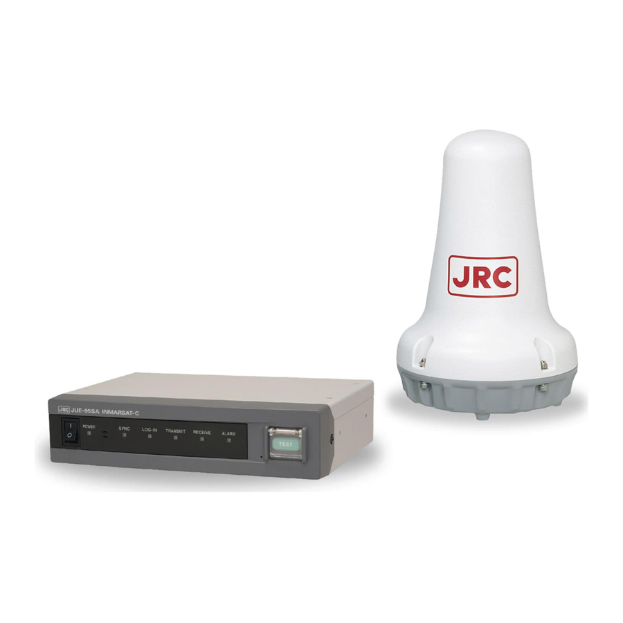
2.3 JUE-95SA Standard components appearance 2.3.1 EME (NAF-742SA/NAF-253SA) The EME is installed above deck for receiving signals from satellites. The EME is covered with a radome. Fig.2.3.1a EME (NAF-742SA) Fig.2.3.1b EME (NAF-253SA) -
Page 18: Ime (Ntf-782Sa)
2.3.2 IME (NTF-782SA) The IME is installed below deck. (9)TEST button (8)RESET button (7)ALARM lamp (6)RECEIVE lamp (5)TRANSMIT lamp (4)LOG-IN lamp (3)SYNC lamp (2)POWER lamp (1)POWER switch Fig.2.3.2a IME Front view (4)Connecter for Security button (1)EME connecter X5 for SB1/2, X6 for SB3/4 (3)DTE connecter (2)PSU connecter Fig.2.3.2b IME Rear view... -
Page 19: Jb (Mpbc40613)
2.3.3 JB (MPBC40613) It can be mounted to bottom part of IME. Fig. 2.3.3 JB 2.3.4 Security Button (NQE-3154) Fig. 2.3.4 Security Button... -
Page 20: Ext Psu (Nbd-577C)
2.3.5 EXT PSU (NBD-577C) Fig.2.3.5 EXT PSU 2.3.6 Coaxial cable (CFQ-5924A3, or CFQ5924A15) It connects EME and IME. Fig.2.3.6 Coaxial Cable... -
Page 21: Optional Components Appearance
2.4 Optional components appearance 2.4.1 DTE (Display: NDZ-127C1, Keyboard: NDF-368) Fig.2.4.1 DTE (NDZ-127C1) 2.4.2 DTE (Display: NDZ-227, Keyboard: NDF-369) Fig.2.4.2 DTE (NDZ-227) and Keyboard(NDF-369) -
Page 22: Printer (Nkg-800)
2.4.3 Printer (NKG-800) Fig.2.4.3 Pinter... -
Page 23: Configuration (Jue-95Sa Standard Components)
2.5 Configuration (JUE-95SA Standard components) 2.5.1 EME (NAF-742SA) Unit: mm Mass: Approx. 1.5kg Fig.2.5.1 EME (NAF-742SA) -
Page 24: Eme (Naf-253Sa)
2.5.2 EME (NAF-253SA) Unit: mm Mass: Approx. 2.4 kg Color: N9 Fig.2.5.2 EME (NAF-253SA) 2-10... -
Page 25: Ime (Ntf-782Sa)
2.5.3 IME (NTF-782SA) Unit: mm Mass: Approx. 1.3kg Fig.2.5.3 IME 2-11... -
Page 26: Jb (Mpbc40613)
2.5.4 JB (MPBC40613) Unit: mm Mass: Approx. 1.1kg Fig.2.5.4 JB 2-12... -
Page 27: Security Button (Nqe-3154)
2.5.5 Security Button (NQE-3154) NQE-3154 MADE IN JAPAN 4-φ4.5 Unit:mm Mass:0.35kg Fig.2.5.5 Security button 2-13... -
Page 28: Ext Psu (Nbd-577C)
2.5.6 EXT PSU (NBD-577C) Specification Input voltage: AC 100/220V (typical), ±10% 50/60Hz (typical), Single phase DC 24V (typical), +30%, -20% Output voltage: DC 24V Caution Before installation, do the following procedure. 1. Set the plug “P1” to suitable receptacle according to the input voltage. -
Page 29: Coaxial Cable (Cfq-5924A3, Cfq5924A15)
2.5.7 Coaxial Cable (CFQ-5924A3, CFQ5924A15) Unit: mm Type Length Mass CFQ5924A15 Approx. 1.4kg 15m(±0.5m) CFQ-5924A3 Approx.2.3kg 30m(±1.0m) Minimum bending radius: 46mm Fig.2.5.7 Coaxial Cable 2-15... -
Page 30: Optional Equipment Dimensional Drawing
2.6 Optional Equipment Dimensional drawing 2.6.1 DTE (Display: NDZ-127C) Unit: mm Mass: Approx. 4.5kg Fig.2.6.1 DTE (Display: NDZ-127C1) 2-16... -
Page 31: Dte (Keyboard: Ndf-368)
2.6.2 DTE (Keyboard: NDF-368) Unit: mm Mass: 0.4kg Fig.2.6.2 DTE (Keyboard: NDF-368) 2-17... -
Page 32: Dte (Display: Ndz-227)
2.6.3 DTE (Display: NDZ-227) 2-18... -
Page 33: Dte (Keyboard: Ndf-369)
2.6.4 DTE (Keyboard: NDF-369) Unit : mm Mass : 0.4kg Fig.2.6.4 DTE (Keyboard: NDF-369) 2-19... -
Page 34: Printer (Nkg-800)
2.6.5 Printer (NKG-800) Fixing Unit: mm Fix the printer on the desk with the hook Mass: Approx. 3.7kg and loop fastener, attached to the printer base. Fig.2.6.5 Printer 2-20... -
Page 35: Chapter 3. Operation
(*2) Press Test button to confirm status of JUE-95SA in this situation Press Test button again after you confirmed the status of JUE-95SA, then all LEDs are turned off again. (*1) Security warning transmission is transmitted when security button is pressed on this situation. -
Page 36: Cancellation Of Security Alert
3.1.7 Optional DTE When DTE is connected to JUE-95SA, refer an operation manual of JUE-85 (option). Main functions can be used when the DTE connected to JUE-95SA are mentioned below. -S&F message communication (Telex, Facsimile, Data, and E-mail) -Data Reporting/Polling (Position, Call Log, and Alarm pack) - Page 37 Remarks (1) POWER Switch Power ON/OFF the MES. (8) RESET Button To reset the status of JUE-95SA Refer to 4.6 of this manual and be when it operates abnormally. careful to handle this button. (It seems as a very little hole. Press the switch exists in the hole with narrow object like a wire.)
-
Page 38: Ssas Schedule Confirmation/Setting
3.2 SSAS Schedule confirmation/setting Confirmation and setting of SSAS Alart transmission schedule can be done in SSAS Schedule screen. 3.2.1 SSAS Schedule confirmation 1. Click [Scheduled Transmission] on [MENU LIST]. Then below mentioned screen is displayed. Fig. 3.2.1a Scheduled Transmission screen 2. - Page 39 Fig. 3.2.1c SSAS Schedule screen display 5. Select SSAS Schedule you want to set from SSAS Schedule #1 to#5. 6. Confirm below mentioned data on above screen. ■Requesting Interval ■LES ■Destination Code & Subscriver’s No. ■Network Type ・ E-Mail ・ Telex ・...
- Page 40 *When Network Type is Telex ・ IA5 ・ ITA2 *When Network Type is except Telex ・ DATA *When Network Type is PSTN ■ Modem Type ・ V22 ・ V22bis ・ V32bis NOTE 1.Empty column is displayed when winIST failed to receive the data. In this case, carry out following procedure and confirm again.
-
Page 41: Setting Ssas Schedule
3.2.2 Setting SSAS Schedule 1. Click Scheduled Transmission on MENU LIST, then Scheduled Transmission screen is opened. Fig. 3.2.2a Scheduled Transmission screen 2. Press [Ctrl+F10] key after the data of Scheduled Transmission is displayed on the screen. 3. Following window is displayed. Then, enter 4-digit password and click [SET] button. Fig. - Page 42 4. Following SSAS Schedule screen is displayed when correct password is entered. Fig. 3.2.2c SSAS Schedule screen (E-mail selected) 5. Select SSAS Schedule you want to set from SSAS Schedule #1 to#5. 6. Input Requesting Interval within the range of 0 to 99. 7.
- Page 43 *When E-mail or Special Access is selected to Network Type 9 Input Destination Code and Subscribers Number by alphabet (capital letter and small letter), 6 character or less. 10 Select Character Code from following choices. ・ IA5 ・ DATA 11. Set Security Alart ON/OFF. 12.
- Page 44 *When PSTN is selected to Network Type 9. Input Destination Code and Subscribers Number. Input Destination Code to first box (from left) within the range of 0 to 999. Input Subscribers Number to second box (from left) by 12-digit figure. 10.
- Page 45 NOTE 1. All data of SSAS Scheduled #1~#5 is written onto INMARSAT terminal when [SET] button is pressed. 2. The data can not be set when winIST failed to receive the data. 3. Following pop-up message is displayed when incorrect data is input and [SET] button is pressed.
- Page 46 NOTE Fig. 3.2.2g LES2 data setup error window ・Error! Please set SSAS Schedule #● LES2 data from 100 to 163! Response: Set the LES No. to second box (from left) of SSAS Schedule #●, within the range of 100 to 163. Fig.
- Page 47 NOTE Fig. 3.2.2j Prefix Code data setting error window ・Error! Please set SSAS Schedule #● Prefix Code data from 0 to 99! Response: Set the Prefix Code of SSAS Schedule #●, within the range of 0 to 99. Fig. 3.2.2k Subscriber’s Number setting error window ・Error! Please set SSAS Schedule #●...
- Page 48 NOTE Fig. 3.2.2m Character Code data setup error display 1 ・Error! Please set Scheduled Transmission #● Character Code IA5 or ITA2! Response: Select Character Code of SSAS Schedule #● from IA5 and ITA2. Fig. 3.2.2n Character Code data setup error display 2 ・Error! Please set Scheduled Transmission #●...
-
Page 49: Transmitting Security Alert
3.3 Transmitting Security Alert 3.3.1 Flowchart of Security Alert transmission Means user’s action Push Security button (ON) Means status button depressed again within 30 seconds? The Security Alert is regularly transmitted. Push Security button (OFF) Stop of Security Alert transmission 3.3.2 Security Alert transmission procedure NOTE Security transmission causes no reactions of terminals. - Page 50 NOTE <Discontinuing transmission procedure when button is pushed by mistake> Push the Button again within 30 seconds: No transmission Push the Button again after 30 seconds passed : Security Alert is transmitted only of first time, and no transmission is carried out after then. Pull out the Power cable from IME rear panel and push the button to turn to OFF, when you want to discontinue transmitting at once regardless of the time after the button is pushed.
-
Page 51: Test Transmission Of Security Alert
3.4 Test transmission of Security Alert 3.4.1 Flowchart of Security Alert Test Transmission This test is done without sending real security alert. Test button Security button Means user’s action Push Test button Means status (The button starts to light) Push Security button (ON) button depressed again within 30... -
Page 52: Procedure Of Security Alert Test Transmission
3.4.2 Procedure of Security Alert test transmission NOTE Confirm all of security buttons are turned off before you start the test transmission. Test transmission is impossible as long as one button is remained turned on. Step1 Push the Test Button of IME, then the button lights. Step 2 Push down Security button. -
Page 53: Chapter 4. Maintenance
The following table shows daily maintenance items using general tools. WARNING Do not check or repair the internal equipment of JUE-95SA by yourself. Any electrical work by any person other than our specialized maintenance persons may cause fire or abnormal operation of this equipment or electrical shock for you. -
Page 54: Troubleshooting
Check all items in the following section to secure normal communication at all times. If any unusual phenomenon occurs in the equipment, send appropriate information to JRC service network to get advice or to request for repair with the results of these items. - Page 55 From previous page Is LOG-IN lamp lit Is ID registered? after 2 minutes ? Application Does Buzzer Exchange sounds during operation? (EME internal GPS error) ALM lamp Countermeasure Alarm/Error status contents Light is disappeared after rebooting: power supply: Blinking with 0.5 Normal return ALM Lamp TX alarm...
-
Page 56: Shadow-Sector Countermeasure
4.4 Shadow-sector countermeasure 4.4.1 Fore and aft directions Shadow-sector is generated when Setup without obstacle down to -5°. some obstacle is exist in slashed part. -5° 4.4.2 Port and starboard directions Setup without obstacle down to -15°. Shadow-sector is generated when some obstacle is existed in slash part. -
Page 57: Reference: Estimation Methods Of Rx/Tx Signal Loss By Physical Obstructions
4.4.4 Reference: Estimation methods of RX/TX signal loss by physical obstructions Attenuation with the obstacle calculates easily in the following method. I. Estimation procedure with the chart (for cylindrical obstacles) i) Estimate the distance (R) from the obstacle; R (m) ii) Estimate the effective diameter (d) of the obstacle;... - Page 58 II. Estimation procedure with the chart ( for un-cylindrical obstacles) i) Estimate the distance (R) from the antenna to the obstacle R (m) ii) Read the effective propagation radius (r) at R meter distance (at point A) from the antenna in the Chart II-1 r (m) iii) Estimate the obstacle area (S ) just occupying effective propagation...
- Page 59 Chart 4.4c The loss due to un-cylindrical obstacle NOTE *When the satellite is existed under lower elevation angle area, sometimes the communication might be impossible due to fading or weather condition.
-
Page 60: Noise Countermeasure (Interference With Other Equipment)
4.5 Noise countermeasure (interference with other equipment) Earthing of EME antenna is highly recommended when trouble is caused in transmission (noise interference, e.t.c.) due to occurrence of interference with other communication device. Earth bolt MTL318538A(Option) Fig. 4.5 Earthing of EME antenna... -
Page 61: Countermeasure
4.6 Countermeasure If the equipment does not operate normally even following procedure is performed, please consult JRC service agent. Take care not to touch any parts PC board. Abnormal operation of IME In case of the heavy fluctuation of the voltage or frequency of the power source, or thunderbolt and etc., IME may not operate normally. -
Page 62: After Service
4.7.2 When ordering repair When a failure has been detected, check it according to the Trouble shooting described in this manual. When abnormalities are still accepted, stop operation and contact the purchasing dealer, JRC agent or one of the JRC branches. - Page 63 When disposing packaging material, follow the rules of the pertinent local government. CAUTION Ask JRC to abandon JUE-95SA (EME). When the lithium battery is short-circuited, receives the impact or it gets wet because of water, it causes generation of heat, the explosion, and the ignition if this is not defended.
- Page 64 4-12...
-
Page 65: Chapter 5. Specification
CHAPTER 5. SPECIFICATION 5.1 JUE-95SA (EME and IME) Table 5.1 Principal Specification of JUE-95SA Class of Inmarsat -C MES Class 1 Frequency range Transmission 1626.5-1646.5 MHz Reception 1530.0-1545.0 MHz (EME: NAF-742SA) 1537.0-1544.2 MHz (EME: NAF-253SA) Channel spacing 5 kHz EIRP Within +7 - +16 dBW (at 5 degrees elevation angle) -23.7 dB/K minimum... -
Page 67: Chapter 6. Jrc Service Network
CHAPTER 6. JRC Service Network Please contact the dealer from which you purchased the device, or our marketing offices that is nearest to you for any question as to the after-sales service. JRC web site JRC Tokyo Japan http://www.jrc.co.jp JRC Amsterdam http://www.jrceurope.com/... - Page 70 For further information,contact: Not use the asbestos http://www.jrc.co.jp Marine Service Department Telephone : +81-3-3492-1305 Facsimile : +81-3-3779-1420 e-mail : tmsc@jrc.co.jp AMSTERDAM Branch Telephone : +31-20-658-0750 Facsimile : +31-20-658-0755 e-mail : service@jrceurope.com SEATTLE Branch Telephone : +1-206-654-5644 Facsimile : +1-206-654-7030 e-mail : marineservice@jrcamerica.com...
Need help?
Do you have a question about the JUE-95SA and is the answer not in the manual?
Questions and answers