Table of Contents
Advertisement
Quick Links
Advertisement
Table of Contents

Related Manuals for JRC JFE-380


Summary of Contents for JRC JFE-380
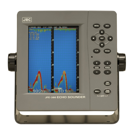
- Page 1 JFE-380 JFE-380 Echo Sounder Echo Sounder INSTRUCTION INSTRUCTION MANUAL MANUAL...
-
Page 3: General Information
General Information Thank you for purchasing the JFE-380 Echo-Sounder manufactured by Japan Radio Co., Ltd.. The JFE-380 conforms to the IMO (International Maritime Organization) performance standards, enabling seabed displays and digital depth displays. Before attempting to operate this equipment, please read this instruction manual thoroughly to ensure correct and safe operation in accordance with the warning instructions and operation procedures. -
Page 4: Before You Begin
Before You Begin Symbols Used In This Manual To ensure that the equipment is used safely and correctly, and that the operator and third parties are not exposed to danger or damage, pictograms are used in this manual and on the equipment itself. -
Page 5: Usage Hints
Usage Hints Do not remove the cover of this set. Otherwise, you may touch a high-voltage part and suffer from an electrical shock. Do not dismantle or modify this equipment. Failure to observe this warning may result in fire, electric shock, or damage. - Page 6 There are no customer-serviceable parts inside. Unauthorized inspections and repairs could cause fires and electrical shock hazards. Please call our field representative or your nearest JRC office for inspection and repair services. Use only the specified fuses.
- Page 7 Please contact JRC or its agent for the electrical installation of this equipment. Electrical installations carried out by other than the qualified staff may result in faulty operation. Do not install or operate the equipment where subject to temperatures more than 55 or less than -15 .
- Page 8 When removing the power cord, be sure to remove the power cord terminal correctly. If the power cord is pulled, the cord may be damaged resulting in a fire or an electrical shock. Do not install the units on the place being poor ventilation.
-
Page 9: External View
External View External View vii... -
Page 10: Explanation Of Terms
Explanation of Terms Beam angle: The angle that sound waves spread out from the transducer. Sound waves spread out in a conical manner taking the center of the bottom surface of the transducer at the apex of the cone. Bubbling: The phenomenon where the image of the seabed is interrupted due to air bubbles caused by the ship's hull or the propeller during a voyage. -
Page 11: Table Of Contents
Contents General Information ....................Before You Begin ......................Usage Hints ........................External View ....................... Explanation of Terms ....................viii 1. Introduction ......................1.1 Function ......................…. 1.2 Feature ......................…. 1.3 Components ....................... 1.4 Construction ...................... 1.5 System Configuration ..................2. Control Panel ......................3. - Page 12 Setting Primary (Secondary) Transducer………………………………………. Setting Adjustment of Date and Time…………………………………………… 4.6 Printer Control Setting……………………………………………………………… Setting Print Output………………………………………………………………… Setting Print Mode………………………………………………………………….. Setting Log Book Print ……………………………………………………………. Setting Log Output Length………………………………………………………... Setting Transfer Speed…………………………………………………………….. Setting Printer Model Selection…………………………………………………… 4.7 Communication Setting…………………………………………………………….. Setting Depth Output………………………………………………………………. Setting Alarm Output……………………………………………………………….
-
Page 13: Introduction
This information is gained by using ultrasonic waves sent from the transducer that are then reflected off the sea bottom and picked up again by the transducer. The JFE-380 also has the following functions: (1) depth alarm, (2) power fail alarm, (3) output of depth data, (4) output of depth and power fail alarms. -
Page 14: Components
50kHz (with cable 20,30,40m) NKF-345 NKF-392C 200kHz (with cable 20m) Printer NKG-91 External Buzzer CGC-300B Flush mounting kit BRBX05339 Table mounting kit BRBX05353 50kHz or 50kHz or 50kHz-A 50kHz-A 50kHz or 50kHz-A JFE-380-25 JFE-380-25 JFE-380-55 JFE-380-22 JFE-380-25 1. Introduction 2... -
Page 15: Construction
1.4 Construction Equipment Outline The following shows the external dimensions of the JFE-380. 1. External Dimension of JFE-380 Unit : mm Mass : 3.3kg Unit : mm Mass : 2.7kg 2. Dimensions of AW-154F/AW-154F-50 Matching box Unit : mm Mass : 4kg... - Page 16 External Dimensions of Transducer mounting The external dimensions illustrated below are for the standard equipment. Please refer to the separately supplied drawings if your specifications are not standard. 1. NKF-341/NKF-345 (Installed on ship’s bottom) Unit : mm Mass : 22kg 2.
-
Page 17: System Configuration
1.5 System Configuration 1. Introduction 5... -
Page 18: Control Panel
2. Control Panel This section describes the names and functions of the control panel, and its controls. Figure 2-1 Control Panel Name Function Cancels the buzzer. MENU Displays the menu. Move a cursor. Selects an item. MODE Selects a display mode. Cancels an item or printing. -
Page 19: Display
3. Display 3.1 Standard mode (dual frequency) Standard mode displays real time sounding echoes. Depth cursor By primary and secondary transducer setting, dual display data will change position. FWD sounding data is displayed on the right side. Please see page 27 Depth TD position Depth unit... -
Page 20: History Mode
3.2 History mode History mode displays past 12hour or 24 hour depth graph and real time sounding. Keel height value Note : LAT/LON display needs to connect position data. 3. Display 8... -
Page 21: Docking Mode
3.3 Docking mode Docking mode displays depth data. By primary and secondary transducer setting, dual display data will change position. FWD sounding data is displayed on the right side. Please see page 27 A F T : 2 0 0 k H z F W D : 5 0 k H z Note : LAT/LON display needs to connect position data. -
Page 22: Operation
4. Operation 4.1 Basic Operation Turning Power ON/OFF [PWR/PANEL] To turn on power, press the [PWR/PANEL] key for about three seconds. To turn off power, press the [PWR/PANEL] key and the [BRILL] key for about three seconds. Adjusting Control Panel Illumination [PWR/PANEL] On echo sounder working, press the [PWR/PANEL] key, the brightness level is displayed in the bar graph. -
Page 23: Gain Control [Gain+][Gain-]
Gain control [GAIN+] [GAIN-] Gain can be set to 31 stages of 0 30. Whenever [GAIN+] key is pressed, the sensitivity is raised. Whenever [GAIN-] key is pressed, the sensitivity is lowered. Keep pressing [GAIN+] key and [GAIN -] key to the setting of auto range at the same time for about three seconds. -
Page 24: Selecting Display Mode [Mode]
Selecting Display Mode [MODE] Each time you press the MODE key, the display mode changes. Single frequency: Each time you press the MODE key, the display mode changes as follows. Standard mode History mode Docking mode Dual frequency: Each time you press the MODE key, the display mode changes as follows. Single frequency standard mode (primary), Single frequency standard mode (secondary), Dual frequency standard mode,... -
Page 25: Cancelling Menu [Clr]
Cancelling Menu [CLR] This key uses with menu functions. When it keeps pressing the key while printing, the printer is canceled printing. Stopping Buzzer [ACK] The buzzer sound stops when the key is pressed after the alarm generated, and the alarm is displayed on the screen. -
Page 26: Right And Left Key Cursor [Cursor]
Right and Left Key of Cursor [CURSOR ] When it is a history mode When the key is pressed, a position cursor is moved left, and it moves accelerating when keeping pressing it. When the key is pressed, a position cursor is moved right, and it moves accelerating when keeping pressing it. -
Page 27: Menu List
4.2 Menu List Menu Tree 1 Default settings shown in underline 4. Operation 15... - Page 28 Menu Tree 2 Default settings shown in underline 4. Operation 16...
-
Page 29: Display Setting
4.3 Display Setting The following sub menu is displayed with [MENU] / DISPLAY A present selection item is displayed by a yellow character. DISPLAY Move a yellow character with key. SCROLL SPEED When or the [ENT] key is pressed after a necessary CLUTTER INTERFERENCE item is selected, the item setting content is displayed. -
Page 30: Setting Auto Gain
Setting Auto Gain The setting method of sensitivity is selected. Make GAIN a yellow display, press or the [ENT] key, and select it from the following, set content. Set content AUTO/MANUAL AUTO This equipment automatically sets sensitivity. At this time, STC becomes “LONG" regardless of the setting of “INITIAL>STC"... -
Page 31: Setting Cursor Display
Setting Cursor Display The cursor display method in a standard mode and a history mode is selected. Make CURSOR a yellow display, press or the [ENT] key, and select it from the following, set content. Set content OFF/ON/AUTO When the cursor key is operated, it makes an error of the cursor without displaying it. Whenever the cursor key is operated, the cursor is displayed. -
Page 32: Alarm Setting
4.4 Alarm Setting The following menu is displayed with [MENU] ALARM ALARM A left, set content is an initial value. MODE CONTINUOUS DEPTH ALARM > SYSTEM ALARM > A present selection item is displayed by a yellow character. Selecting items move a yellow display with key. -
Page 33: Setting Depth Alarm
Setting Depth Alarm Make DEPTH ALARM a yellow display, press or the [ENT] key, and the following menu is displayed. DEPTH ALARM ALARM CONT Selecting items move a yellow display with key. DEPTH SETTING ALARM CONT The operation of the depth alarm is selected. Make ALARM CONT a yellow display, press or the [ENT] key, and select it from the following, set content. -
Page 34: Setting System Alarm
Setting System Alarm Make SYSTEM ALARM a yellow display, press or the [ENT] key, and the following menu is displayed. SYSTEM ALARM DEPTH LOST Selecting items move a yellow display with key. TX ALARM RX ALARM BUBBLE ALARM PRINTER ALARM DEPTH LOST The alarm operation when sea bottom cannot be detected is selected. - Page 35 RX ALARM When the receiving signal becomes abnormal, the alarm operation is selected. Make RX ALARM a yellow display, press or the [ENT] key, and select it from the following, set content. Set content OFF/ON The receiving signal alarm doesn't operate. When abnormality occurs in the receiving signal, the receiving signal alarm is started.
- Page 36 Each Alarm and Alarm Display (Screen Display) list Alarm Display Alarm (Screen Display) Primary depth alarm DEPTH1(ALR) Secondary depth alarm DEPTH2(ALR) Primary sea bottom lost DEPTH1(LOST) Secondary sea bottom lost DEPTH2(LOST) Primary transmission abnormality TX1(LEVEL) Primary receiving abnormality RX1(LEVEL) Primary bubbling RX1(BUBBLE) Secondary transmission abnormality TX2(LEVEL)
-
Page 37: Initial Setting
4.5 Initial Setting The following menu is displayed with [MENU] INITIAL INITIAL MEMORY LENGTH 24hr A left, set content is an initial value. COLOR DEPTH DISPLAY MODE TRAN PRIMARY SECONDARY DATE/TIME A present selection item is displayed by a yellow character. Selecting items move a yellow display with key. -
Page 38: Setting Depth Display
DAY1 / DAY2 / NIGHT1 / NIGHT2 Make SCREEN or CHARACTER a yellow display, press or the [ENT] key, and the number of 1 6 is displayed. Select a color tone of the favor number with key and press the [ENT] key because each content of characters is shown in the following. -
Page 39: Setting Primary (Secondary) Transducer
Setting Primary (Secondary) Transducer Various settings concerning the installation of the transducer are selected. Make PRIMARY or SECONDARY a yellow display, press or the [ENT] key, and the following menu is displayed. PRIMARY FREQ A left, set content is an initial value, and SECONDARY is the FWD (AFT) same content. - Page 40 STC (STC curve) Make STC a yellow display, press or the [ENT] key, and select it from the following, set content. Set content SHORT/MIDDLE/LONG SHORT 40log is selected by the STC curve on a primary (secondary) side. MIDDLE 30log is selected by the STC curve on a primary (secondary) side. LONG 20log is selected by the STC curve on a primary (secondary) side.
-
Page 41: Setting Adjustment Of Date And Time
Setting Adjustment of Date and Time Date/Time/Time difference/GPS synchronization is set. Make DATE/TIME a yellow display, press or the [ENT] key, and the following menu is displayed. DATE/TIME DATE A left, set content is an initial value. TIME DIFF +00:00 Selecting items move a yellow display with key. -
Page 42: Printer Control Setting
4.6 Printer Control Setting Note: JFE-380 electrically stores last 12or 24hours depth data. Optional printer runs after only your PRINTER CONT menu PRINTER [ENT] pressing. The following menu is displayed with [MENU] PRINTER CONT A present selection item is displayed with a yellow PRINTER CONT character. - Page 43 When PRINTER PORT OUT is “PRINTER" COPY A present screen display is printed. The direction of paper feed is length against the screen. HISTORY All the memorized depth data is graphically printed. The direction of paper feed is time. Secondary data is printed following primary in display screen for dual frequency. On single frequency mode, only displaying frequency data is printed.
- Page 44 2. HISTORY print mode 3. LOG print mode 24hours history 30minutes log 1hour time mark 4. Operation 32...
-
Page 45: Setting Log Book Print
MEMORY LENGTH setting as 12 hours. If 24 hours is set, 0.5min runs 1min interval. “OFF” stops automatic LOG book print mode. NOTE: When GPS position data is connected to JFE-380, LAT/LON position data would print. Select “LOG BOOK PRINT” with key. -
Page 46: Communication Setting
4.7 Communication Setting The following menu is displayed with [MENU] COMMUNICATION COMMUNICATION DEPTH A left, set content is an initial value. ALARM SYSTEM PRINTER PORT OUT PRINTER A present selection item is displayed by a yellow character. Selecting items move a yellow display with key. - Page 47 Depth output $SDDBS, xxx.x, f, xxx.x, M, xxx.x, F(CR)(LF) $SDDBT, xxx.x, f, xxx.x, M, xxx.x, F(CR)(LF) $SDDBK, xxx.x, f, xxx.x, M, xxx.x, F(CR)(LF) (1) Depth value after compensation (in feet) (2) Depth value after compensation (in meters) (3) Depth value after compensation (in fathoms) (4) No check sum $SDDPT, xxx.x, x.x, x.x *hh (CR)(LF) (1) (2) (3) (4)
- Page 48 Alarm output $SDALR,hhmmss.ss,xxx,A,A,c--c*hh<CR><LF> (2) (3)(4)(5) (6) (1) Time of alarm condition change,UTC (2) ID number of the alarm source 351 primary depth alarm 352 secondary depth alarm 353 primary depth lost 354 secondary depth lost 356 printer paper is not good 357 printer connection is not good 360 primary transmit signal is not good 361 primary receive signal is not good...
-
Page 49: Setting System Output
Setting System Output Make SYSTEM a yellow display, press or the [ENT] key, and select it from the following, set content. Set content OFF/ON Maintenance system information is not output with the constant period. Maintenance system information is added to the depth output port and it outputs. Select the content by and press the [ENT] key. -
Page 50: Installation
5. Installation When installing the equipment, securely connect the earth lead to the earth terminal. Failure to connect the earth may result in electric shock in the event of a fault or power leak developing. Do not install or operate the equipment where subject to temperatures 55°C or higher or –15°C or lower. -
Page 51: Installing The Recorder Unit
5.1 Installing the Recorder Unit Flush-Mount Equipment Figure 3-1 5. Installation 39... -
Page 52: Wall-Mount Equipment
Wall-Mount Equipment Figure 3-2 5. Installation 40... -
Page 53: Installing The Transducer
5.2 Installing the Transducer The external dimensions illustrated below are for the standard equipment. Please refer to the separately supplied drawings if your specifications are not standard. NKF-341 5. Installation 41... -
Page 54: Nkf-345
NKF-345 5. Installation 42... -
Page 55: Nkf-392C
NKF-392C 5. Installation 43... -
Page 56: Connecting Components
5.3 Connecting Components Notes: 1. The shield of each cable must be securely attached to the connectors and must not contact any other connectors, etc. 2. Casings must be grounded securely to the ship’s hull using copper plates. 3. The exterior is to be grounded to the ship’s hull cable bands. 4. -
Page 57: Maintenance & Check
6. Maintenance & Check Do not open the equipment to inspect or repair internal circuits. Inspection or repairs by anyone other than a specialized technician may result in fire, electrical shock, or malfunction. If internal inspection or repair is necessary, contact our service center or agents. 6.1 Daily Maintenance The life of the equipment depends on the execution situation of the daily maintenance and check. -
Page 58: Maintenance Function
6.2 Maintenance Function Make [MENU] MAINTENANCE a yellow display by , press , and the following menu is displayed. A present selection item is displayed by a yellow character. MAINTENANCE SELF TEST Selecting items move a yellow display with key. ALARM LOG When or the [ENT] key is pressed after a necessary item... - Page 59 KEY UNIT Make KEY UNIT a yellow display, press or the [ENT] key, and the operation unit self test starts. When the key on the operation panel is pressed, the name of the pressed key is displayed. However, it returns to the self test menu when the [CLR] key is pressed, and the [CLR] key is judged. PRINTER TEST Make PRINTER TEST a yellow display, press or the [ENT] key, and the test pattern is output (print).
-
Page 60: Displaying Alarm Log
Displaying Alarm Log Make ALARM LOG a yellow display, press or the [ENT] key, and last 20 memorized alarm histories are displayed. Each alarm log displays alarm occurred position (position data need), date/month/year, time, alarm No. and alarm status. Alarm No. is from 01 to 13. The No. meaning is shown in page Alarm status has “A: alarm is still lasting”... -
Page 61: Executing Line Monitor
Executing Line Monitor Make LINE MONITOR a yellow display, press or the [ENT] key, and the following menu is displayed. LINE MONITOR NAV/DEPTH Navigation data/Depth output NAV/DEPTH ALR Input/Output PRINTER Printer port PRINTER Make the monitor item a yellow display, press or the [ENT] key, and the input/output data of the serial port is displayed, and input data is displayed in the upper part of the screen, and output data is displayed under the screen. -
Page 62: Replacing Printer Paper
6.3 Replacing Printer Paper Do not cut your hand in the blade tip of the paper cutter. Name Model type Remarks H-7ZPJD0384 TF50KS-E2D for NKG-91 printer Printer paper H-6ZCAF00252A for DPU-414 printer After turning off the power supply of this equipment, exchange papers. On NKG-91 when the printer cover is opened while turning on, the alarm of “NO PAPER"... -
Page 63: Replacing Backup Battery
If the backup battery is low, “Please do connection setting of transducers.” Message will pop up with turning on. See page 37, 4.8 Master Reset. If your JFE-380 becomes like this, please contact our agent to order replacing the battery. Backup lithium coin cell battery CR2032 Note : For the safety, turn off the main power switch of echo sounder. - Page 64 3 Replace the battery. Stick the small width (narrower than 5mm) slotted screwdriver between the battery and the battery socket. Lift the screwdriver to take off the battery. Set the new battery in the battery socket. The positive (+) terminal is upside. Push the battery until stayed in horizontally.
-
Page 65: Troubleshooting
6.5 Troubleshooting The table below shows the principal symptom, the cause, and measurements. As a result, request the repair to our company or our agency when it is not possible to recover to normal operational condition. Symptom Cause Measurements The screen doesn't appear The breaker of AC100-230V of the Make the breaker of AC100-230V of the even... -
Page 66: Replacing Fuses
6.6 Replacing Fuses Exchange the fuse for the one of our specification. Exchange it after confirming the cause to which the fuse is blown. Moreover, turn off the main switch of the power supply CQD-2082 when you exchange fuses (Press sign side). -
Page 67: Repair Parts
(2) of the interface block. Temporarily remove the cable to the external device. If the fuse blows again, the Interface Block (CQD-2082) may be faulty. Contact JRC or its agent. (See the list of offices at the end of this manual.) -
Page 68: Consider Installation
7. Consider Installation • Do not install the JFE-380 where subject to the following conditions as such conditions may cause failures and reduce the life of the equipment. 1. Where liable to be splashed with water. 2. Where ventilation is poor. -
Page 69: After-Sales Service
Note that such inspection and maintenance is subject to charge. Please consult JRC or its agent for further details of any part of the afterservice conditions. Contact: See list at end of manual. -
Page 70: Warranty & After-Sales Service
If any failure occurs in the product during its normal operation in accordance with the instruction manual, the dealer or JRC will repair free of charge. In case that any failure is caused due to misuse, faulty operation, negligence or force major such as natural disaster and fire, the product will be repaired with charges. -
Page 71: Disposal
9. Disposal 9.1 Disposal of this equipment If this equipment is to be disposed, please follow the guidelines of the local body governing the location at which the equipment is disposed of. 9. Disposal 59... -
Page 72: Specifications
10. Specifications Display 6.5 inch TFT LCD (640 x 480 pixels) Frequency 200kHz / 50kHz or 50kHz-A Echo color 8 colors or 8 level monochrome Digital depth 3 digit (0.0m to 99.9m : 0.1m steps, 100m over : 1m steps) Range 100m 200m... -
Page 73: Appendix
Appendix Noise Bubble Noise Bubble Interruption Interference Noise from other ship Plankton layer Appendix 61... -
Page 74: Actual Pictures
Actual Pictures Zero line DISP TRANS figure A Seabed DISP SURF DISP KEEL Seabed Zero line Third reflection of bottom Second reflection of bottom Seabed In case of a shallow seabed or when increasing the amplifier sensitivity, two seabed lines may be recorded. -
Page 75: Seabed Quality Change
Seabed Quality Change Rock In case of a hard seabed composed of rocks etc., its return trails long, as shown in right chart. In case of a soft seabed made of mud, seaweed, etc., they poorly reflect an ultrasonic wave to result in thin recording of the seabed with short trail. -
Page 76: Abrupt-Sloped Seabed
Abrupt-Sloped Seabed Side lobe False echo A dim echo may sometimes appear along an abrupt slope of seabed, as if it were floating above the slope, when recording. In case of flat seabed, thin second return of seabed may sometimes appear, which is slightly below the actual seabed. - Page 77 The echo of a seabed with abrupt slope is recorded as a lone difficult to see and less discriminative, since it tends to accompany with a false echo due to the side lobe and the inherent property of directivity. In particular, a seabed with abrupt slope and heavily rugged surface provided an echo very difficult to display on the recording.
-
Page 78: China Rohs
(Indicates that this toxic or hazardous substance contained in at least one of the homogeneous materials used for this part is above the limit requirement in SJ/T 11363-2006.) 7ZPNA2002A JRC Code No. : Management Methods on Control of Pollution from Electronics Information Products of the People's Republic of China... - Page 80 For further information,contact: Not use the asbestos http://www.jrc.co.jp Marine Service Department Telephone : +81-3-3492-1305 Facsimile : +81-3-3779-1420 e-mail : tmsc@jrc.co.jp AMSTERDAM Branch Telephone : +31-20-658-0750 Facsimile : +31-20-658-0755 e-mail : service@jrceurope.com SEATTLE Branch Telephone : +1-206-654-5644 Facsimile : +1-206-654-7030 e-mail : marineservice@jrcamerica.com...
Need help?
Do you have a question about the JFE-380 and is the answer not in the manual?
Questions and answers