MIMAKI UJV-160 Operation Manual
Uv inkjet printer
Hide thumbs
Also See for UJV-160:
- Daily care manual (16 pages) ,
- Operation manual (156 pages) ,
- Care and maintenance (32 pages)
Table of Contents
Advertisement
Quick Links
Advertisement
Table of Contents

Subscribe to Our Youtube Channel
Related Manuals for MIMAKI UJV-160


Summary of Contents for MIMAKI UJV-160
- Page 1 MIMAKI ENGINEERING CO., LTD. D201854-17...
-
Page 2: Table Of Contents
TABLE OF CONTENTS CAUTION ................ vi CAUTION ................vi Requests .................vi FCC Statement (USA) .............vi Interference to televisions and radios ......vi Foreword .................vii About this operation manual ...........vii Features .................viii Safety Precautions ............ix Symbols ................ix CHAPTER 1 Before Use Installing this machine ..........1-2 Where to install ............1-2 Working Environmental Temperature .......1-3 Moving this machine ..........1-3... - Page 3 CHAPTER 2 Basic Operations Operation flow ............2-2 Turning the power ON/OFF ........2-4 Turning the power ON ..........2-4 Turning the power OFF ..........2-5 Maintenance operation at startup ......2-6 Preventing nozzle missing while power-off ....2-8 Setting media ............2-12 Setting roll media ............
- Page 4 Initializing the settings .......... 3-19 MACHINE SETUP ..........3-20 Setting time .............3-20 Information ..............3-21 Checking the power supply voltage ......3-22 Setting the scanning for curing pattern ....3-23 Setting level of the paper width sensor ....3-24 Other useful functions ........... 3-25 Changing displayed language .........3-25 Data clear ..............3-25 Displaying the information of this machine ....3-26...
- Page 5 Wiper cleaning ............. 4-27 Refill antifreeze liquid ........... 4-29 Refilling antifreeze liquid ......... 4-30 Replacing of UV LED filter ........4-31 CHAPTER 5 In Case of Trouble Check first when a trouble occurred ...... 5-2 The power is not turned on ........5-2 Data is not drawn ............
-
Page 6: Caution
CAUTION DISCLAIMER OF WARRANTY: THIS LIMITED WARRANTY OF MIMAKI SHALL BE THE SOLE AND EXCLUSIVE WARRANTY AND IS IN LIEU OF ALL OTHER WARRANTIES, EXPRESS OR IMPLIED, INCLUDING , BUT NOT LIMITED TO, ANY IMPLIED WARRANTY OF MERCHANTABILITY OR FITNESS, AND MIMAKI NEITHER ASSUMES... -
Page 7: Foreword
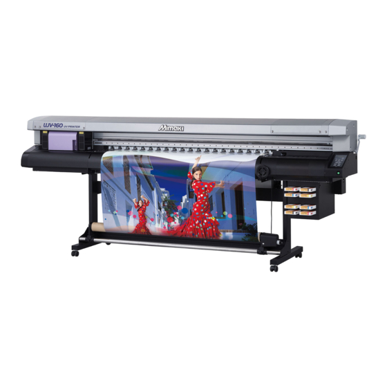
Congratulations on your purchase of a MIMAKI "UJV-160" model of UV ink jet printer. The UV Inkjet Printer UJV-160 is a printer with ultraviolet ray curing ink (UV ink). Read this Operation Manual carefully and make the most effective use of your printer. -
Page 8: Features
Features Characteristics of this machine are introduced here. We hope this information helps your understanding on drawing with this machine together with operation method explained in this book. Ultraviolet ray curing ink Direct printing on media is allowed by using newly developed ultraviolet curing ink. Printable types of media has increased. -
Page 9: Safety Precautions
Safety Precautions Symbols Pictorial signs are used in this Operation Manual for safe operation of and in prevention of damages to this machine. The indicated sign is different depending on the content of caution. Symbols and their meanings are given below. Please follow these instructions as you read this manual. Examples of symbols Failure to observe the instructions given with this symbol can result in death or serious injuries to personnel. - Page 10 Warnings for use WARNING • Be sure to setup the appropriate ventilator in case of using this machine in a closed room or a room with bad ventilation. Cautions for constructing exhaust outlet Please follow the cautions below to avoid breakdown of this machine. (1) The opening area of the exhaust outlet requires more than half of the duct entrance area.
- Page 11 Be sure to use only the UV LED unit 110V : This machine ... 100 to 120V recommended by Mimaki. 220V : This machine ... 200 to 240V We would take no responsibility for any troubles caused through the use of a UV LED unit other than our recommendation.
-
Page 12: Precautions For Use
Precautions for use CAUTION Protection against dust Periodic exchange parts • Use this machine in a room that is not dusty. • There are some parts which must be • When leaving the work place after the periodically replaced. Contract with working hours, be sure to remove the media distributors or dealers for maintenance. - Page 13 Safety Precautions CAUTION UV light Hot parts • A little UV light spills around the UV LED • When touching hot parts, be sure to wear unit. UV light applied to your skin might heat-insulating gloves to protect your hands. cause inflammation and/or skin cancer.
-
Page 14: Precautions For Installation
Safety Precautions Precautions for installation CAUTION A place exposed to direct On an inclined surface A place where temperature or sunlight humidity varies significantly • Use this machine under the following environmental conditions. • Operating environment : 15 to 35 ℃ (Available) 20 ~... - Page 15 CHAPTER 1 Before Use In this chapter, the parts names and setting procedures before use are explained. Installing this machine.......... 1-2 Where to install ............1-2 Working Environmental Temperature ......1-3 Moving this machine ..........1-3 Configuration and Function ......... 1-4 Front/ Side ..............
-
Page 16: Installing This Machine
Installing this machine Where to install Before assembling this machine, secure a sufficient space to install. Decide the place considering the machine size and a space required for drawing. Width Lengh Height Total Weight 3300 mm 780 mm 1290 mm Approx.260 kg For the installation site, see also “Precautions for installation”. -
Page 17: Working Environmental Temperature
Installing this machine Working Environmental Temperature Use this machine in an environment of 15 to 35°C to ensure reliable drawing. Depending on the ambient temperature, the heater temperature may not rise to the set value. Moving this machine Move this machine according to the following steps when this machine is required to move on the step-free same floor. -
Page 18: Configuration And Function
Configuration and Function Front/ Side Y Bar Carriage The guide to move the car- The head to print and the UV LED are in it. Scans riage. from side to side. Flushing Tray Y Bar Handle Absorber in the Tray absorbs the waste ink when the print head is Raises/lowers the Y Bar and adjusts the head flushing. -
Page 19: Rear/ Side Of The Main Power Switch
Configuration and Function Rear/ Side of the main power switch Pre-Heater Preheats the media before printing. (Located inside the platen) Water Heating Device Keeps the ink at a proper temperature. Clamp Lever (Rear) Interlocked with the Clamp Lever (side). Voltage selector switch Roll holder Switches 100 to 120V and 200 to 240V depending on the supply voltage using this... -
Page 20: Support Table (Front/Back)
Support Table (Front/Back) The tables support the rigid media feed. Use both the front and the back table together. Support Table (Front) Support Table (Back) -
Page 21: Operation Panel
Configuration and Function Operation Panel The operation panel is used for each operation. Display UV READY lamp Displays the status of this Shows the irradiation condition of machine, set items and errors. the UV LED on both sides. Lights in green when the UV LED is irradiat- CONSTANT lamp ing. -
Page 22: Carriage And Uv Led Unit
Carriage and UV LED Unit A print head for drawing and two UV LED Units are mounted on the carriage. Depending on the condition of this machine, the position of the carriage is different. • Do not expose your naked eyes directly to the light irradiated from the lighting UV LED. Wiper The wiper on the right front side of this machine removes the ink attached on the head at ink filling or clean- ing. -
Page 23: Heater
Configuration and Function Heater Pre-heater and Print heater are equipped on the platen. The Pre-heater is used for pre-heating of the media prior to printing to prevent rapid temperature changing. The Print-heater improves the image quality in printing. • While heating, the platen is very hot. Not to get burned, when replacing media, lower the heater temperatures and wait until the platen temperature drops. -
Page 24: Connecting The Cables
Connecting the cables Connecting the USB2.0 interface cable Connect a computer to this machine with the USB2.0 interface cable. • Your RIP is required to support USB2.0 interface. • If USB2.0 interface is not installed in your computer, ask a RIP vender near you or our branch office. -
Page 25: Setting The Ink Cartridge
Setting the ink cartridge Insert the ink cartridges into the ink station. Ink Type Ink Type Color Magenta Cyan LF-200 (SPC-0558) Yellow LH-100 (SPC-0597) Black White Magenta Cyan Yellow LF-140 (SPC-0728) Black Light Magenta Light Cyan White Cleaning solution *1: For 600cc pack, a special eco-cartridge is needed. *2: Use for cleaning the head. - Page 26 • Never disassemble the ink cartridge. • Never refill the ink cartridge with ink. Refilling the ink cartridge can cause a trouble. Remember that Mimaki assumes no responsibility for any damage caused by the use of the ink cartridge replenished with ink.
-
Page 27: About Media
About Media The sizes of media that can be used and the method of handling are described here. Usable media size Maximum width 1620 mm (Rigid media : 1600mm) Minimum width 210 mm Maximum print length 1600 mm Thickness 0.2mm to 10 mm Φ180 mm or less Outside diameter Weight... -
Page 28: About Antistatic Sheet
About antistatic sheet The antistatic sheet is used to prevent the media from clinging due to static. Use this when the media clings due to static and it influences the media feeding. For the attaching procedure, refer to the setup manual attached with the antistatic sheet. •... -
Page 29: Local>And
<LOCAL>and<REMOTE> <LOCAL> and <REMOTE> are shown on the display of this machine. < L O C A L . 1 > * R E MO T E . 1 * LOCAL When <LOCAL> is diplayed, the followings can be set. All keys are available. - Page 30 1-16...
-
Page 31: Basic Operations
CHAPTER 2 Basic Operations In this chapter, the procedure from media preparation to drawing are explained. Operation flow ........2-2 Preparing Heaters....... 2-32 Turning the power ON/OFF....2-4 Changing temperature settings of the heater .............2-32 Turning the power ON ......2-4 Confirming the heater temperature ..2-33 Turning the power OFF ...... -
Page 32: Operation Flow
Operation flow Turning the power on See "Turning the power ON/OFF" P.2-4) Setting media See "Setting media" ( P.2-12) Preparing Heaters See "Preparing Heaters" ( P.2-32) Head cleaning See "Head cleaning" ( P.2-36) - Page 33 Operation flow Head cleaning See "Head cleaning" ( P.2-36) Drawing an image from See "Drawing an image from data" P.2-38) data Turning the power off See "Turning the power ON/OFF" P.2-4)
-
Page 34: Turning The Power On/Off
Turning the power ON/OFF Turning the power ON This machine has the following power switches. Main power switch 1 / 2:They are on the side of this machine. Power switch : It is on the right front side of this machine. Normally, use this switch to turn the power ON/OFF. -
Page 35: Turning The Power Off
Turning the power ON/OFF Turning the power OFF When finishing the use of this machine, turn the power OFF with the power switch on the front side of this machine. When turning the power off, check the followings. • Data is not being receivied from the computer, or there is any undrawn data. •... -
Page 36: Maintenance Operation At Startup
Maintenance operation at startup When the power on maintenance is valid, the operation below is performed depending on the status at startup of this machine. "Perform cleaning automatically when the For the power on maintenance setting, refer to P.4-17 power supply is turned on". (Supported from the firmware ver.2.00) If hot water turned cool Preparation for hot water starts. - Page 37 Turning the power ON/OFF If ink in subtank is not enough Fill ink into the subtank. SUP P L Y I NG I NK * * * * * - - - - - - - - - - - - - - - •...
-
Page 38: Preventing Nozzle Missing While Power-Off
Preventing nozzle missing while power-off Even while the power switch is off, the machine starts periodically and executes various functions to prevent nozzle missing. (Supported from the firmware ver.1.90) • Do not turn off the power switch at startup from the sleep mode. When the sleep operation has been completed, the machine turns off the power switch automatically. - Page 39 Turning the power ON/OFF When Sleep Maintenance is set When sleep refresh or sleep cleaning is set for sleep maintenance, additionally perform the refresh operation and cleaning operation to prevent nozzle clogging. (Supported from the firmware ver.2.40) ● Sleep Refresh Perform the refresh operation while the U J V - 1 6 0 s t a r t - u p...
- Page 40 When turning the power OFF ● Do not turn the main power switch OFF. If the main power switch is ON, the power periodically turns on and the nozzle missing prevention function is operated. If the main power switch is OFF, the sleep function does not work and this may cause nozzle missing. ●...
- Page 41 Turning the power ON/OFF When this machine is left unused for a long time • Be sure to turn off the main power switch on the side of this machine. ( P.2-4) • Remove the media being set. • To avoid the ink curing at the head, cover the head standby position (right or left depending on the standby position) with the provided shading sheet .
-
Page 42: Setting Media
Setting media This machine can be used with roll media and leaf media. For the media to be used, refer to P.1-13 "Usable media size". Setting roll media Set roll media to the roll holder on the back of this machine. •... - Page 43 Setting media Insert the roll media into this machine. Pinch roller • Slanted the media, the roll media can be smoothly inserted. ( 1 ) Pull the media out to the top of the platen. ( 2 ) Insert the media between the platen and the pinch roller. •...
- Page 44 Pull out the roll media evenly, then turn the clamp lever to the back. • Pulling some positions of the media lightly, confirm that the the roll media is evenly pulled out, then turn the clamp lever to the back. Unlock the roll stopper.
- Page 45 Setting media Prepare the take-up device. • Set an empty core to the take-up device. Core Take-up device Press the key to select “ROLL” . MED I A S E L EC T RO L L < > L EA F •...
- Page 46 Take-up device Select the take-up direction of media with the switch of the take-up device. Lever, top (REVERSE) : Winds the media with the printed side facing in. Lever, middle (OFF) : Does not wind the media. Lever, bottom (FORWARD) : Winds the media with the printed side facing out.
- Page 47 Setting media Torque limiter adjustment The take-up device has a torque limiter. The take-up torque can be adjusted with the torque limiter. (The torque limiter is set at the maximum value as a default.) If the tension is too strong to use a thin media, lower the take-up torque with the torque limiter. •...
-
Page 48: Setting Leaf Media
Setting leaf media Unlike roll media, leaf media does not need to be fixed with the roll holders. • To prevent the rigid media being jammed into the Y bar, raise the head in advance. P.2-26) Turn the clamp lever to the front. Clamp lever Set the leaf media. - Page 49 Setting media Turn the clamp lever to the back. • Set the media straight. Select “LEAF” with the key. MED I A S E L EC T RO L L < > L EA F Media detection starts. DE T EC T I NG WI D T H P L E A SE WA I T ( 1 ) The media width is detected.
-
Page 50: Setting Rigid Media
Setting rigid media To set thick media such as a board (up to 10mm), attach the support tables on the front and the back of this machine. • To prevent the rigid media being jammed into the Y bar, raise the head in advance. P.2-26) •... - Page 51 Setting media • To set media flat, move the screws on both sides of the support table (8 screws on each side) to adjust the tilt or the parallelism of the support table. Adjust the position of the rigid media Rigid media retainer rack retainer rack right/ left (the front of this machine)
- Page 52 Set the rear support table (the back of this machine). • Unlike the front table, the rear support table does not have a stick (rigid media retainer). ( 1 ) Lift up the table until it stops. ( 2 ) Set the support table so that the protrusions on protrusions both sides of this machine come between the concave parts of the support table.
- Page 53 Setting media Set the rigid media. • Remove the rigid media retainer from the front sup- port table. • From the back of this machine, insert the media between the pinch rollers and the platen. • For the long media, pull out the auxiliary bars of the support table, and set the media on them.
- Page 54 Turn the clamp lever to the back. • Set the media straight. Adjust the head height. • Adjust the head height according to the media thickness. ( P.2-26) Select “BOAD” with the key . MED I A S E L EC T V BOAD 2-24...
- Page 55 Setting media The media detection starts. DE T EC T I NG WI D T H P L E A SE WA I T ( 1 ) The media width is detected. ( 2 ) The media is fed and the rear end of the media is detected. ( 3 ) When the detection is completed, <LOCAL>...
-
Page 56: Adjusting The Head Height
Adjusting the head height Adjust the head height according to the thickness of the media used. Set a media. • Set a media. ( P.2-12, P.2-18, P.2-20 ) Attach the Y bar handle to turn to the right. • Turn the handle to the right to raise the Y bar above the set media. - Page 57 Setting media Return the carriage to the left. • When the power is on Return the carriage with the key. • When the power is off Move the carriage holding the handling part. • The head unit is fragile. To move the head unit, push the handling part as shown below.
-
Page 58: Detect The Media Width
Detect the media width ng contents of “Setting the media width ( P.3-18)”, the method for detecting media Depending on the setti differs. When the setting value of “MEDIA WIDTH” is 100 to 1620mm, detect the media with the procedures in "Media detecting method (detecting width manually)". - Page 59 Setting media Media detecting method (detecting width manually) Depending on the set media, press the ME D I A S E L E C T jog key RO L L < > L E A F Specify the right edge position of the ME D I A W I D T H D E T E C T media.
-
Page 60: Changing The Print Origin
Changing the print origin The print start position (origin) can be changed. when <LOCAL> is displayed, press the < L OC A L . 1 > one of keys. • Origin setup screen is displayed. Move the head with the one of OR I G I N S E T U P keys. - Page 61 Setting media The guide for the print origin position The print start position (origin) in the depth direction (X') is located at the ORIGIN mark. The origin in the scanning direction (Y') is positioned at 10 mm from the right end of the media. Changed the setting from [MARGIN] in SET UP menu.
-
Page 62: Preparing Heaters
Preparing Heaters Set the heater temperature according to the media used. Changing temperature settings of the heater The temperature of the heater can be changed by [HEATER] of the setup mode. P.3-11 "Changing the heater temperature setting") • When purchased, the heater temperature is set "OFF". •... -
Page 63: Confirming The Heater Temperature
Preparing Heaters • The heater temperature can be preset according to the media used. P.3-6 "Setting the print condition in a set" • The temperature set by the operations above does not reflect the heater settings of the type registration. The set continues until the power is turned off or the temperature is newly set with the following conditions. -
Page 64: Test Drawing
Test drawing Make test drawing to check blur or missing caused by nozzle clogging. • When the following message is displayed, it cannot print. Start drawing after the message has disappeared. “WATER NOT READY” :The water temperature in the water heating device has not reached the predetermined value. - Page 65 Test drawing Test drawing ends. • <LOCAL> is displayed. Check the drawing. • When the drawing is normal, data can be printed. • When the drawing is abnormal, execute head cleaning. ( P.2-36) • When needed, adjust the origin position. ( P.2-30) Abnormal pattern Normal pattern...
-
Page 66: Head Cleaning
Head cleaning If test pattern is not normal, execute head cleaning. There are 3 types of head cleaning. Select this when there is a dozen line missed on the test pattern. Normal P.2-36 Select this when there are several lines missed on the test pattern. Wiping P.2-37 The wiper wipes. -
Page 67: Cleaning By Wiping
Head cleaning Cleaning by Wiping When <LOCAL> is dipslayed, press the < L OC A L . 1 > key. CLEANING Select [wiping] with the key, C L E A N I NG and press the key. T Y P E : w i p i n g ENTER Select execution of cleaning for each... -
Page 68: Drawing An Image From Data
Drawing an image from data Starting the drawing • If the temperature of the water heating device has not reached the predetermined value, a message is displayed. It does not draw in such cases. When the display is disappeared, drawing can be started. •... -
Page 69: Cancelling The Drawing
Drawing an image from data Cancelling the drawing To stop the drawing, stop the drawing operation and erase the received data from this machine. Press the key while drawing. REMOTE * R EMO T E . 1 * 2 . 5 mm •... -
Page 70: Subtank Maintenance
Drawing an image from data Subtank Maintenance Execute following procedures when an error about subtank ( P.5-6 Error 148) occurs, or when the nozzle is not unclogged after cleaning. When <LOCAL> is displayed, press the < L OC A L . 1 > key. -
Page 71: Useful Function
CHAPTER 3 Useful Function In this chapter, the operations to make this machine easier to use, and the function settings are explained. If dots misalign ........3-2 Initializing the settings....... 3-19 Checking UV ink curing level ....3-4 MACHINE SETUP........ 3-20 Setting the print condition in a set .. -
Page 72: If Dots Misalign
If dots misalign When the thickness of the media, the height of the head, the type of the ink used or the dot size of data to be printed is changed, follow the steps below and adjust the ink drop position for Bi-directional (Bi) printing to print properly. - Page 73 If dots misalign Correct the dot position of the selected DROP . POS c o r r e c t mode with the key. 6 0 0 d p i NORMA L / 4 : • Correction value : -400 to 400 •...
-
Page 74: Checking Uv Ink Curing Level
Checking UV ink curing level Deteriorating of the UV LED may lower the ink curing level. Check the ink curing level and adjust the UV LED light intensity as needed. Set a media for drawing pattern. When <LOCAL> is displayed, press the <... - Page 75 Checking UV ink curing level Check the drawing pattern after the test drawing. • If the UV light intensity is weak, a good pattern cannot be drawn. In this case, change the light intensity with P.3-15 "Setting the UV LED level" and execute the test drawing again.
-
Page 76: Setting The Print Condition In A Set
Setting the print condition in a set Settings on printing. When <LOCAL> is displayed, press the < L OC A L . 1 > key. FUNCTION Press the key. ENTER F U NC T I ON S E T U P <... -
Page 77: Setting The Print Condition
Setting the print condition Change the settings according to the purpose. When <LOCAL> is displayed, press the < L OC A L . 1 > key. FUNCTION Press the key. ENTER F U NC T I ON S E T U P <... - Page 78 Setting the print condition Setting list The settings of the print condition are as follows. The underlined has been set as default. These settings can be registered on the “Type”. Item Setting Outline Prints the pattern to adjust the media MEDIA COMP( P.3-9) -9999 to 0 to 9999...
-
Page 79: Setting Media Compensation
Setting media compensation When changing the type of media or the heater temperature, adjust the media feeding. If wrongly adjusted, it may not print clearly such as stripes on the print. • When the heater temperature is changed, check the [ CONSTANT ] lamps light and it has reached the preset temperatures, and then adjust. - Page 80 Setting media compensation Press the key twice to start ENTER [ 1 ] print. MED I A COMP . < e n t > • The machine scans for UV irradiation to cure ink on the drawn pattern. ( P.3-23) Check the compensation pattern, then [ 1 ] MED I A COMP .
-
Page 81: Changing The Heater Setting
Changing the heater setting Changing the heater temperature setting Set each item of [SET TEMP]. Change the set temperature of the Pre-heater and Print-heater built SET TEMP in the platen. When <LOCAL> is displayed, press the < L OC A L . 1 > key. -
Page 82: Setting Media Feed
Setting media feed Set the media feed. When <LOCAL> is displayed, press the < L OC A L . 1 key. FUNCTION Press the key. ENTER F U NC T I ON S E T U P < E N T > Select the type 1 to 4 with the S E T U P key, and press the... -
Page 83: Setting The Print Method
Setting the print method Set about printing. When <LOCAL> is displayed, press the < L OC A L . 1 > key. FUNCTION Press the key. ENTER F U NC T I ON S E T U P < E N T > Select the type 1 to 4 with the S E T U P key, and press the... - Page 84 Setting the print method Item Description STANDARD Standard drawing quality QUALITY FINE High quality drawing (drawing speed is slower) FAST High speed drawing (image quality is slightly inferior) Draws in both directions when the head moves on the media at Bi-D drawing.
-
Page 85: Setting The Uv Led Level
Setting the UV LED level Set when you do not want to light the UV LED. When <LOCAL> is displayed, press the < L OC A L . 1 > key. FUNCTION Press the key. ENTER F U NC T I ON S E T U P <... -
Page 86: Setting The Adsorbing Level
Setting the adsorbing level Set when you want to change the adsorbing level. (Supported from the firmware ver.1.80) When <LOCAL> is displayed, press the < L OC A L . 1 > key. FUNCTION Press the key. ENTER F U NC T I ON S E T U P <... -
Page 87: Setting The Priority
Setting the priority For the items below, select the setting priority from this machine’s setting or the computer’s setting. Items: Print mode/ Ink layers When <LOCAL> is displayed, press the < L OC A L . 1 > key. FUNCTION Press the key. -
Page 88: Setting The Media Width
Setting the media width When you know the width of the media to use, you can record the media width. (Supported from the firmware ver.2.00) When <LOCAL> is displayed, press the < L OC A L . 1 > key. FUNCTION Press the key. -
Page 89: Initializing The Settings
Initializing the settings Initializes the print condition settings. When <LOCAL> is displayed, press the < L OC A L . 1 > key. FUNCTION Press the key. ENTER F U NC T I ON S E T U P < E N T > Press the key. -
Page 90: Machine Setup
MACHINE SETUP Setting time Set the current time. When <LOCAL> is displayed, press the < L OC A L . 1 > key. FUNCTION Select the [MACHINE SETUP] with the F U NC T I ON key, and press the MA CH I N E S E T U P <... -
Page 91: Information
MACHINE SETUP Information Check the machine information, and print the list of the settings. When <LOCAL> is displayed, press the < L OC A L . 1 > key. FUNCTION Select the [MACHINE SETUP] with the F U NC T I ON key, and press the MA CH I N E S E T U P <... -
Page 92: Checking The Power Supply Voltage
Checking the power supply voltage Check the setting of the power supply voltage supplied to the water heating device. When <LOCAL> is displayed, press the < L OC A L . 1 > key. FUNCTION Select the [MACHINE SETUP] with the F U NC T I ON key, and press the MA CH I N E S E T U P <... -
Page 93: Setting The Scanning For Curing Pattern
MACHINE SETUP Setting the scanning for curing pattern Select whether scanning or not for curing ink when printing the nozzle check or the media compensation. When <LOCAL> is displayed, press the < L OC A L . 1 > key. FUNCTION Select the [MACHINE SETUP] with the F U NC T I ON... -
Page 94: Setting Level Of The Paper Width Sensor
MACHINE SETUP Setting level of the paper width sensor To detect media width including transparent film, change the sensitivity of the sensor. • Even if FINE is set on the sensor level, a wide space between the paper width sensor and the media can reduce in sensitivity of the sensor and interrupt detection of the media. -
Page 95: Other Useful Functions
Other useful functions Changing displayed language Select the displayed language. When <LOCAL> is displayed, press the < L OC A L . 1 > key. FUNCTION Select the [DISPLAY] with the F U NC T I ON key, and press the key. -
Page 96: Displaying The Information Of This Machine
Other useful functions Displaying the information of this machine When <LOCAL> is displayed, press the < L OC A L . 1 > key. ENTER Remaining amount of ink The information is displayed < L OC A L . 1 > MMC C Y Y K K sequentially with the key. - Page 97 CHAPTER 4 How to care In this chapter, maintenance of this machine such as ink replacemnet or cleaning are explained. Maintaining..........4-2 Perform cleaning automatically when When this machine is left unused for a long the power supply is turned on ..4-17 time ............
-
Page 98: Maintaining
Maintaining To use this machine for a long time, be sure to perform maintenance of this machine periodically or when- ever necessary. When this machine is left unused for a long time • Be sure to turn off the main power switch on the side of this machine. ( P.2-4) •... -
Page 99: Cleaning Exterior Surfaces
Maintaining Cleaning exterior surfaces If exterior surfaces of the machine is dirty, dampen a soft cloth with water or a neutral detergent diluted with water, squeeze it and wipe the surfaces. Cleaning the platen The platen is easy to become dirt with lint, paper dust or the like after cutting media. For a conspicuous stain, wipe it off with a soft-hair brush, a dry cloth, a paper towel or the like. -
Page 100: Cleaning The Paper Width Sensor
Maintaining Cleaning the paper width sensor The paper width sensor detects the end face of media. If ink for printing is attached on the sensor, the sen- sor may not detect the paper width for the low sensitivity. Wipe out the lower face of the sensor periodically. Paper width sensor... -
Page 101: Ink Cartridge
Ink cartridge Replacing with a new ink cartridge Replace of ink cartridges in the following cases. Display Outline The ink in an ink cartridge is low. < L OC A L . 1 > • Drawing can be continued, but the ink may end during drawing. Early I N K N E A R E N D : M _ _ _ _ _ _ replacement is recommended. - Page 102 When the 600 cc cartridge is used ● Setting the 600 cc cartridge • The 600 cc cartridge can be used only by setting the cartridge to the printer. • The 440 cc and 600 cc cartridges can be used together on one printer. Prepare the 600 cc cartridge.
-
Page 103: Ink Cartridge Trouble
Ink cartridge Ink cartridge trouble When a trouble is detected on ink cartridges, a warning message appears. Printing, cleaning and all other operations using ink becomes unusable. In this case, immediately replace the ink cartridge with a new one. • Do not leave the ink cartridge unreplaced for a long time. This will cause the nozzle clogging and the printer must be repaired by a service person. -
Page 104: Cleaning The Flushing Tray
Cleaning the flushing tray Replace the flushing filter in the flushing tray once a month. • F-200 Cleaning kit • Flushing filter Contents of the (SPC-0568) (SPC-0577) cleaning kit • Gloves • Paper towel • Goggles • When replacing, be sure to put on the supplied goggles and gloves, since you may get ink in your eyes. - Page 105 Cleaning the flushing tray Remove the flushing tray on the left of this machine. • Lift it up to remove. Replace the filter in the flushing tray with a new one. Set the flushing tray. • Fit the tray into this machine not to be lifted or dis- located.
-
Page 106: Avoiding Ink Dripping At Printing
Avoiding ink dripping at printing Ink droplets from the mist at drawing may arise on the bottom of the carriage. As the ink droplets may drip and stain the media or cause blur or dot missing, clean the bottom of the carriage periodically. •... - Page 107 Avoiding ink dripping at printing Dip the cleaning swab into the cleaning Bottom of the carriage solution, and clean the side surface of the head. • Do not wipe the nozzle face of the head. It may cause nozzle clogging. •...
-
Page 108: When The Waste Ink Tray Is Full
When the waste ink tray is full Waste ink used for head cleaning gathers in the waste ink tray and the wiper tank. Periodically check the waste ink tray and the wiper tank and when they are full, dispose of the ink. •... - Page 109 When the waste ink tray is full Cover Put the waste ink into a tank with a cover. • Holding the waste ink tray with the cover with both hands, and dispose of the ink. • Before putting the ink into the tank, put paper on the Waste ink tray floor.
-
Page 110: Disposing Of The Waste Ink In The Wiper Tank
Disposing of the waste ink in the wiper tank Turn the power on. • After initializing, <LOCAL> is displayed. When <LOCAL> is displayed, press the < L OC A L . 1 > key. FUNCTION Select the [MAINTENANCE] with the F U NC T I ON key, and press the MA I N T E N A NC E... - Page 111 When the waste ink tray is full Set the wiper tank. • Turn the tank holding the tank cover, and close the tank cover. • Fit the waste ink box cover. Press the key. ENTER CH A NG E W I P T A N K COMP L E T E D : e n t Press the...
-
Page 112: Setting Nozzle Face Cleaning Time
Setting nozzle face cleaning time When set times of drawing are completed, nozzle face of the head is cleaned automatically to remove ink droplets on the nozzle face. When <LOCAL> is displayed, press the < L OC A L . 1 > key. -
Page 113: Perform Cleaning Automatically When The Power Supply Is Turned On
Perform cleaning automatically when the power supply is turned on Depending on the subtank status, the slider moves to the right and left continuously with the buzzer sound. (Supported from the firmware ver.2.00) When <LOCAL> is displayed, press the < L OC A L . 1 > key. -
Page 114: Regular Maintenance Of White Ink
Regular maintenance of white ink White ink precipitates easier than other inks. • If not printing more than two weeks, white ink may precipitate in the ink cartridge or inside of this machine. • When an ink precipitates, the nozzle may be clogged and it can not draw normally. •... - Page 115 Regular maintenance of white ink Pull out the white ink cartridge from the Wh i t e M a i n t e . _ _ _ _ W_ _ _ R EMO V E C A R T R I DGE ink station.
- Page 116 Regular maintenance of white ink When the next screen is displayed, set Wh i t e M a i n t e . _ _ _ _ W_ _ _ the white ink cartridge to the ink station S E T C A R T R I DG E again.
- Page 117 Regular maintenance of white ink 4-21...
-
Page 118: Setting The Maintenance Performed While The Power Is Turned Off
Setting the Maintenance Performed while the Power Is Turned off You can perform maintenance on the printer automatically even when the power is turned off. There are two types of maintenance: Head refreshing and cleaning. (Supported from the firmware ver.2.40) Setting the refresh operation while the power is turned off The printer starts and performs the refresh operation at intervals set beforehand (OFF/10 to 120 minutes) while the power is turned off. -
Page 119: Setting The Cleaning Operation While The Power Is Turned Off
Setting the Maintenance Performed while the Power Is Turned off Setting the cleaning operation while the power is turned off The printer starts and performs the cleaning operation at intervals set beforehand (OFF/4 to 48 hours) while the power is turned off. (Sleep cleaning function) •... - Page 120 4-24...
-
Page 121: If Blur Or Missing Remains
If blur or missing remains When blur or dot missing does not improve after head cleaning, perform subtank maintenance. Subtank Maintenance Insert an ink cartridge into the ink station. • Insert an ink cartridge firmly. When <LOCAL> is displayed, press the <... -
Page 122: Head Wiping
Head Wiping When turning the power of this machine on, the head is automatically wiped to avoid the dirt of media. • The wiping starts when the head reaches the set temperature after turning the power on. • Wiping here is for avoiding stain of the media, therefore the used ink is a very little. •... -
Page 123: Wiper Cleaning
Wiper cleaning The wiper sweeps ink stuck on the nozzle of the head. The wiper becomes tainted with ink or dusts during the operation of this machine. In order to keep the head in good condition, clean the wiper frequently. •... -
Page 124: Cleaning Swab
Wiper cleaning Wipe out the dirt of the wiper with the cleaning swab. • Wipe the places shown in the right. If sponges are dirty, replace the sponge. • Remove the sponge with tweezers or the like, then set the provided new sponge. Wipe the the dirt of the wiper rubber with the cleaning swab. -
Page 125: Refill Antifreeze Liquid
Precautions in handling the antifreeze liquid • Be sure to wear goggles and gloves for handling the antifreeze liquid. • Use the recommended antifreeze liquid by Mimaki. If not, the water heating device may be broken. (Supplied antifreeze liquid : SPC-0394 [1000cc x 2 bottles]) •... -
Page 126: Refilling Antifreeze Liquid
Refill antifreeze liquid Refilling antifreeze liquid If a lack of water error is displayed, refill antifreeze liquid-mixed water. To fill with the water, refill about 200cc. Mix antifreeze liquid with water. (1) Mix 1 part antifreeze liquid with 2 parts water. (2) Put the mixed water into a provided syringe. -
Page 127: Replacing Of Uv Led Filter
Replacing of UV LED filter To use this machine for a long time, clean the UV LED filter periodically (about once a month). • Put on supplied goggles and gloves. Ink may splash into the eye. • When a screw is dropped in replacing of the filter, contact a distributor in your district or our office. - Page 128 Replacing of UV LED filter Replace 2 UV LED filters on the front covers. UV LED filter Attach the 2 front covers of the UV LED unit and the left cover of the main unit. • Attach in reverse order of step 3, 4. 4-32...
- Page 129 CHAPTER 5 In Case of Trouble In this chapter, the solutions for troubles of this machine or error messages are explained. Check first when a trouble occurred ....5-2 The power is not turned on ........5-2 Data is not drawn ............5-2 Message appears ............
-
Page 130: Check First When A Trouble Occurred
Check first when a trouble occurred When a trouble occurred, check the followings. If the trouble is not solved after checking, contact a distribu- tor in your district or our office. The power is not turned on It causes for improper connection of the power cable or the computer cable. Check that the cables are properly connected. -
Page 131: Problems Of Drawing Result
Check first when a trouble occurred Problems of drawing result If the drawing result has a problem, follow the table below. If the problem does not improve after that, con- tact a distributor in your district or our office. Problem Solution Lines / blur (1) Execute the head cleaning. -
Page 132: Troubles Displaying Messages
C o l o r o f I N K : M M C C Y Y K K • Use the MIMAKI ink. < L O C A L . 1 > N O N - O R I G N L : M M C C Y Y K K •... - Page 133 Troubles displaying messages Message Solution • Set a media to the left. M E D I A P O S I T I O N • Execute Station maintenance and execute Dispose of the ink in the wiper tank. ( P.4-14) W I P E R T A N K...
-
Page 134: Error Message
Error message When an error message is displayed, follow the table below and solve the problem. If the same error message is displayed again, contact a distributor in your district or our office. Message Solution • Turn the power of this machine off and turn it on after a while. E R R O R 0 6 •... - Page 135 Troubles displaying messages Message Solution • Turn the power of this machine off and turn it on after a while. E R R O R 4 0 • If the same error message appears again, contact a distributor in your M O T O R district or our office to call for service.
- Page 136 Message Solution • Turn the power of this machine off and turn it on after a while. E R R O R 7 5 • If the same error message appears again, contact a distributor in your U V [ * : * * ] P W R ( L ) district or our office to call for service.
- Page 137 Troubles displaying messages Message Solution • Turn the power of this machine off and turn it on after a while. E R R O R 1 5 0 • If the same error message appears again, contact a distributor in your N E G A .
- Page 138 5-10...
- Page 139 CHAPTER 6 Appendix In this chapter, specifications and functions of this machine are explained. Specifications ............6-2 Specifications ............6-2 Ink Specifications ............6-3 Warning label ............6-4 Function Flowchart ..........6-6...
-
Page 140: Specifications
2 UV LED units (equipped on the carriage) UV unit and the built-in UV power Tray Waste ink tank USB2.0 Interface MRL-II B <ESC/P Level 2 base, MIMAKI original command> Command Less than 58dB (FAST-A, Front & Rear 1m) Stand-by Continuous sound in Less than 65dB Noise... -
Page 141: Ink Specifications
Specifications Ink Specifications For the detail, ask a distributor in your district or our office. LF-200 Item Specification Exclusive UV ink cartridge Feature Black, magenta, cyan, yellow, white Ink type 440CC, 600CC Capacity of ink cartridge One year from the date of manufacture Life During storage 15 ℃... -
Page 142: Warning Label
Warning label The warning labels are adhered on this machine. Be sure to fully understand the warning on the labels. If any of the warning label has become too soiled to read the warning message or the labels has come off, purchase a new one from a distributor in your district or our office. - Page 143 Warning label...
-
Page 144: Function Flowchart
Function Flowchart < L OCA L . 1 > OR I G I N S E T UP OR I G I N S E T UP 0 . 0 - - - - * * OR I G I N * * D A T A C L E AR * * DA T A C L E AR * * <... - Page 145 Function Flowchart * * T E S T DRAW * * HARD EN CHEC K HARDE N CHEC K QUA L I T Y : S T ANDARD SCAN D I R . : Y S i : STANDARD/FINE/FAST : : Y Si/Y Re/Y Bi : When [WIPING] is “ON”...
- Page 146 < L OCA L . 1 > [ # 0 1 ] F UNC T I ON SETUP S E T UP < E N T > F UNC T I ON MAINTENANCE MA I N T ENANCE < E N T > F UNC T I ON MACHINE SETUP MACH I NE S E T UP <...
- Page 147 Function Flowchart To P.6-10 To P.6-14 To P.6-18...
- Page 148 SETUP S E T UP [ 1 ] [ 1 ] MED I A COMP . S E L EC T : T Y P E . 1 MED I A COMP . < e n t > PR I N T S T AR T : e n t :TYPE.2 TYPE.3...
- Page 149 Function Flowchart Print P L E A S E WA I T [ 1 ] MED I A COMP . completed PR I N T I NG AD J US T :-9999 ~ 9999 [ 1 ] F E ED ME T HOD S E T UP : NORMA L : NORMAL/ DIRECT...
- Page 150 From P6-10 [ 1 ] [ 1 ] RE F RE SH RE F RE SH < e n t > WA I T I NG < e n t > [ 1 ] RE F RE SH DRAW I NG <...
- Page 151 Function Flowchart [ 1 ] RE F RE SH WA I T I NG : L E V E L 1 :LEVEL 0 to 3 [ 1 ] RE F RE SH DRAW I NG : L E V E L 1 :LEVEL 0 to 3 [ 1 ] PR I OR I T Y I NK L A Y ERS...
- Page 152 MAINTENANCE MA I N T ENANCE W I P E HE AD W I P E H E AD W I P E HE AD < e n t > HE AD : MMCCY Y K K W I P E NUM . :1 to 9 :ON / OFF :Select the head...
- Page 153 Function Flowchart W I P E HE AD W I P I NG completed W I P E S T AR T : e n t P L E A S E WA I T RESTART RESTART Print DROP . POS c o r r e c t DROP .
- Page 154 From P6-14 MA I N T ENANCE I NK CHANGE I NK CHANGE : _ MCCY _ _ _ I NK CHANGE < e n t > HE AD MMCCY Y K K REMOV E CAR T R I DGE :ON / OFF :Select the head MA I N T ENANCE...
- Page 155 Function Flowchart discharged WA SH I NG I NK CHANGE : _ MCCY _ _ _ WA SH I NG P L E A S E WA I T S E T C L E AN TOO L P L E A S E WA I T I NK CHANGE : M * * * * * * WA SH I NG I NK CHANGE : M * * * * * *...
- Page 156 MACHINE SETUP MACH I NE S E T UP T I ME S E T T I ME S E T T I ME S E T < e n t > 2 0 Y Y . MM . DD h h : mm : s s D o Y o u c h a n g e i t ? : e n t...
- Page 157 Function Flowchart Time setting completed 6-19...
- Page 158 6-20...
- Page 159 D201854-17-10082015...
- Page 160 © MIMAKI ENGINEERING CO., LTD.2015 FW : 2.40...
Need help?
Do you have a question about the UJV-160 and is the answer not in the manual?
Questions and answers