Table of Contents
Advertisement
Advertisement
Table of Contents

Related Manuals for Kyocera Mita KM-1505


Summary of Contents for Kyocera Mita KM-1505
-
Page 1: Service Manual
KM-1505 SERVICE MANUAL Published in June.’01 2BT70760... - Page 2 CAUTION DANGER OF EXPLOSION IF BATTERY IS INCORRECTLY REPLACED. REPLACE ONLY WITH THE SAME OR EQUIVALENT TYPE RECOMMENDED BY THE MANUFACTURER. DISPOSE OF USED BATTERIES ACCORDING TO THE MANUFACTURER’S INSTRUCTIONS. ATTENTION IL Y A DANGER D’EXPLOSION S’IL Y A REMPLACEMENT INCORRECT DE LA BATTERIE. REMPLACER UNIQUEMENT AVEC UNE BATTERIE DU MÊME TYPE OU D’UN TYPE REC- OMMANDÉ...
-
Page 3: Safety Precautions
Safety precautions This booklet provides safety warnings and precautions for our service personnel to ensure the safety of their customers, their machines as well as themselves during maintenance activities. Service personnel are advised to read this booklet carefully to familiarize themselves with the warnings and precautions described here before engaging in maintenance activities. - Page 4 Safety warnings and precautions Various symbols are used to protect our service personnel and customers from physical danger and to prevent damage to their property. These symbols are described below: DANGER: High risk of serious bodily injury or death may result from insufficient attention to or incorrect compliance with warning messages using this symbol.
-
Page 5: Installation Precautions
1. Installation Precautions WARNING • Do not use a power supply with a voltage other than that specified. Avoid multiple connections to one outlet: they may cause fire or electric shock. When using an extension cable, always check that it is adequate for the rated current..................... •... -
Page 6: Precautions For Maintenance
2. Precautions for Maintenance WARNING • Always remove the power plug from the wall outlet before starting machine disassembly....• Always follow the procedures for maintenance described in the service manual and other related brochures............................• Under no circumstances attempt to bypass or disable safety features including safety mechanisms and protective circuits. - Page 7 • Do not pull on the AC power cord or connector wires on high-voltage components when removing them; always hold the plug itself....................... • Do not route the power cable where it may be stood on or trapped. If necessary, protect it with a cable cover or other appropriate item.
-
Page 8: Table Of Contents
CONTENTS 1-1 Specifications 1-1-1 Specifications ............................1-1-1 1-1-2 Parts names ............................1-1-2 (1) Copier ............................. 1-1-2 (2) Operation panel ..........................1-1-3 1-1-3 Machine cross section .......................... 1-1-4 1-1-4 Drive system ............................1-1-5 (1) Drive system 1 (drive motor drive train) ..................1-1-5 (2) Drive system 2 (scanner motor drive train) .................. - Page 9 (18) Image center does not align with the original center..............1-5-18 (19) Image contrast is low (carrier scattering)..................1-5-18 1-5-4 Electrical problems ..........................1-5-19 (1) The machine does not operate when the main switch is turned on..........1-5-19 (2) The drive motor does not operate.
- Page 10 1-6-4 Image formation section ........................1-6-27 (1) Detaching and refitting the image formation unit ................1-6-27 (2) Detaching and refitting the main charger unit ................1-6-28 (3) Detaching and refitting the drum ....................1-6-29 (4) Detaching and refitting the cleaning blade ................... 1-6-31 (5) Replace the developer ........................
-
Page 11: Specifications
1-1-1 Specifications Type ..........Desktop Copying system ......Indirect electrostatic system " × Originals ......... Sheets of paper, books, 3-dimensional objects (Maximum original size: folio/8 14") Original feed system ...... Contact glass: fixed Copy paper ........Drawer: Plain paper (64 - 80 g/m Bypass table: Plain paper (60 - 160 g/m Special paper: Transparencies, letterhead and colored paper Note: Use the bypass table for special paper. -
Page 12: Parts Names
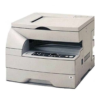
1-1-2 Parts names (1) Copier & ⁄ ¤ Figure 1-1-1 1 Original cover @ Main switch 2 Operation panel # Copy storage section 3 Paper conveying cover handle $ Drawer 4 Paper conveying cover % Platen 5 Multi-Bypass ^ Original size scales 6 Insert guides &... -
Page 13: Operation Panel
(2) Operation panel Inch Metric Figure 1-1-2 1 Start key (Indicator) 8 Add Toner indicator 2 Stop/Reset key 9 Paper Select key 3 Size Select key 0 Drawer indicator 4 Number of Copies/Zoom (+) key ! Multi-bypass indicator 5 Number of Copies/Zoom (–) key @ Misfeed indicator 6 Zoom Input/Enter key # Image mode selection key... -
Page 14: Machine Cross Section
1-1-3 Machine cross section 6 7 2 Light path Paper path Figure 1-1-3 Machine cross section 1 Paper feed section 2 Main charging section 3 Optical section 4 Developing section 5 Transfer and sparation section 6 Cleaning section 7 Charge erasing section 8 Fixing section 1-1-4... -
Page 15: Drive System
1-1-4 Drive system (1) Drive system 1 (drive motor drive train) & As viewed from machine rear Figure 1-1-4 1 Drive motor gear 0 Gear 97/25 2 Gear 67/30 ! Drum drive gear 53 3 Gear 23/16 @ Gear 40/45 4 Gear 37/21 # Gear 41 5 Gear 23... -
Page 16: Drive System 2 (Scanner Motor Drive Train)
(2) Drive system 2 (scanner motor drive train) As viewed from machine rear Figure 1-1-5 1 Scanner motor gear 2 Scanner drive gear 27/13 3 Scanner belt 4 Gear Z23 5 Idle gear 21 6 Gear Z30 1-1-6... - Page 17 1-2-1 Drum Note the following when handling or storing the drum. • When removing the image formation unit, never expose the drum surface to strong direct light. • Keep the drum at an ambient temperature between 10°C/50°F and 32.5°C/90.5°F and at a relative humidity not higher than 85% RH.
-
Page 18: Installation Environment
1-2-3 Installation environment 1. Temperature: 10 - 32.5°C/50 - 90.5°F 2. Humidity: 20 - 85%RH 3. Power supply: 120 V AC, 9 A 220 - 240 V AC, 4.8 A (average 2.5 A) 4. Power source frequency: 50 Hz ±0.3%/60 Hz ±0.3% 5. -
Page 19: Unpacking And Installation
1-3-1 Unpacking and installation (1) Installation procedure Start Unpack. Remove the tapes. Adjust the fixing pressure. Remove the tapes, pads and sheet inside the drawer. Remove the pins holding light source units 1 and 2. Remove the pad inside the machine. Install a toner container. - Page 20 Unpack ^&* Figure 1-3-1 Unpacking 1 Copier ! Waste toner tank spacer 2 Power cord @ Bar code labels 3 Upper pads # Drawer spacer 4 Stay $ Front drawer spacer 5 Outer case % Sheet 6 Bottom pads ^ Instruction handbook 7 Tray spacer &...
- Page 21 Remove the tapes. 1. Remove the 11 tapes. Figure 1-3-2 2. Open the bypass tray and paper conveying cover and then remove the two tapes. Tapes Figure 1-3-3 1-3-3...
- Page 22 Adjust the fixing pressure. 3. Lift the fixing section release levers and close the paper conveying cover. Fixing section release levers Figure 1-3-4 Remove the tapes, pads and sheet inside the drawer. 4. Pull the drawer out and remove the tapes and two pads.
- Page 23 Remove the pins holding light source units 1 and 2. 6. Remove the tapes and two pins for light source unit 1 and 2. Tapes Pins Figure 1-3-7 7. Open the front cover and store the removed pins by securing them on the inside of the cover. The storing locations of the pins are marked inside the front cover.
- Page 24 Install a toner container. 9. Hold the toner container vertically and tap the top 15 times. Turn the container upside-down and tap the top 15 times. Then, hold the container horizontally and shake it from side to side 10 times. Figure 1-3-10 10.
- Page 25 Install a waste toner tank. 11. Install the waste toner tank and close all the covers and drawers. Waste toner tank Figure 1-3-12 Connect the power cord. 12. Connect the power cord and turn the main switch Caution: Never turn the power off or open covers while the copier is driving.
- Page 26 Load paper. 13. Pull the drawer out as far as it will go. 14. Press the drawer bottom plate down and lock it there. Drawer bottom plate Figure 1-3-14 15. Holding the width adjustment lever, move it to align the width guide with the required paper width.
- Page 27 17. Set the paper flush against the left-hand wall of the drawer. * Load paper so that it is kept under the claw of the drawer. * When loading paper into the drawer, make sure that the copy side is facing upward (the copy side is the side facing upward when the package is opened.) * Check that the length and width guides securely...
-
Page 28: Setting Initial Copy Modes
1-3-2 Setting initial copy modes Factory settings are as follows: Maintenance Contents Factory setting item No. Turning auto start function on/off U254 U255 Setting auto clear time 90 s Turning auto preheat/energy saver U256 function on/off Switching copy operation at toner Single mode, 70 U258 empty detectionempty detection... -
Page 29: Copier Management
1-3-3 Copier management In addition to a maintenance function for service, the copier is equipped with a management function which can be operated by users (mainly by the copier administrator). In this copier management mode, default settings can be changed. (1) Executing a copier management item •... -
Page 30: Default Settings
(2) Default settings User status report Drawer paper size Outputs the details of the default settings. Sets the size of paper loaded in the drawer. 1. Select “F01” and press the enter key. 1. Select “F08” and press the enter key. User status report is printed out. - Page 31 Auto preheat time Paper feed shifting adjustment (drawer) Sets the auto preheat time. Adjusts displacement of the copy image. 1. Select “F14” and press the enter key. 1. Select “F20” and press the enter key. 2. Select the setting and press the enter key. 2.
-
Page 32: Maintenance Mode
1-4-1 Maintenance mode The copier is equipped with a maintenance function which can be used to maintain and service the machine. (1) Executing a maintenance item Start Press the stop/reset key, start key and the left copy exposure adjustment key in the order presented and hold them down. -
Page 33: Maintenance Mode Item List
(2) Maintenance mode item list Item Initial Section Maintenance item contents setting* General U000 Outputting an own-status report — U001 Exiting the maintenance mode — U004 Setting the machine number — U005 Copying without paper — Initialization U020 Initializing all data —... - Page 34 Item Initial Section Maintenance item contents setting* Developing U156 Changing the toner control level • Toner feed start level • Toner empty level U157 Checking/clearing the developing drive time — U158 Checking/clearing the developing count — U161 Setting the fixing control temperature Fixing and •...
-
Page 35: Contents Of Maintenance Mode Items
(3) Contents of maintenance mode items Maintenance Description item No. U000 Outputting an own-status report Description Outputs lists of the current settings of the maintenance items, and paper jam and service call occurrences. Purpose To check the current setting of the maintenance items, or paper jam or service call occurrences. Before initializing the backup RAM, output a list of the current settings of the maintenance items to reenter the settings after initialization or replacement. - Page 36 Maintenance Description item No. U005 Copying without paper Description Simulates the copy operation without paper feed. Purpose To check the overall operation of the machine. Method 1. Press the start key. A selection item appears. 2. Select the item to be operated using the copy exposure adjustment keys. Display Operation Only the copier operates.
- Page 37 Maintenance Description item No. U021 Initializing memories Description Initializes the setting data other than that for adjustments due to variations between respective machines, i.e., settings for counters, service call history and mode settings. As a result, initializes the backup RAM according to the specifications depending on the destination selected in U252.
- Page 38 Maintenance Description item No. U030 Checking motor operation Description Drives the drive motor. Purpose To check the operation of the drive motor. Method 1. Press the start key. A selection item appears. Display Motor Drive motor (DM) 2. Press the start key. The motor operates. 3.
- Page 39 Maintenance Description item No. U033 Checking main switch operation Description Turns the main switch on by energizing the main switch off solenoid. Purpose To check the operation of the main switch off solenoid in auto shutoff mode. Method 1. Press the start key. "A" appears. 2.
- Page 40 Maintenance Description item No. U053 Performing fine adjustment of the motor speed Description Performs fine adjustment of the speeds of the motors. Purpose Used to adjust the speed of the respective motors when the magnification is not correct. Method Press the start key. Setting 1.
- Page 41 Maintenance Description item No. U060 Adjusting the scanner input properties Description Adjusts the image scanning density. Purpose Used when the entire image appears too dark or light. Method Press the start key. Setting 1. Change the setting using the zoom +/– keys. Description Setting range Initial setting...
- Page 42 Maintenance Description item No. U065 Adjusting the scanner magnification Adjustment See pages 1-6-22 and 23. U066 Adjusting the leading edge registration for scanning an original on the contact glass Adjustment See page 1-6-24. U067 Adjusting the center line for scanning an original on the contact glass Adjustment See page 1-6-25.
- Page 43 Maintenance Description item No. U088 Setting the input filter (moiré reduction mode) Description Turns moiré reduction mode on and off by switching the input filter on and off. Purpose Used to prevent regular density unevenness (moiré) on halftone image areas of the copy image in text mode and text and photo mode.
- Page 44 Maintenance Description item No. U091 Checking shading Description Performs scanning under the same conditions as before and after shading is performed, displaying the original scanning values at nine points of the contact glass. Purpose To check the change in original scanning values before and after shading. The results may be used to decide the causes for fixing unevenness (uneven density) of the gray area of an image: either due to optical (shading or CCD) or other problems.
- Page 45 Maintenance Description item No. U091 When scanning is performed before shading, the scan value at the machine center should be slightly (cont.) different from those at the machine front and rear. When scanning is performed after shading, there should be no difference between respective values. Any differences between the values at machine front and rear indicates that scanner problem causes the fixing unevenness.
- Page 46 Maintenance Description item No. U093 Setting the exposure density gradient Description Changes the exposure density gradient in manual density mode, depending on respective image modes (text, text and photo, photo). Purpose To set how the image density is altered by a change of one step in the manual density adjustment. Also used to make copy image darker or lighter.
- Page 47 Maintenance Description item No. U093 Setting (cont.) 1. Select the item to be adjusted by lighting a copy exposure indicator using the copy exposure adjustment keys. 2. Adjust the setting using the zoom +/– keys. Copy exposure Description Setting range Initial setting indicator Exp.
- Page 48 Maintenance Description item No. U100 Setting the surface potential Description Changes the surface potential by changing the grid control voltage. Also performs main charging. Purpose To set the surface potential or check main charging. Also used when reentering data after initializing the set data.
- Page 49 Maintenance Description item No. U101 Setting high voltages Description Changes the developing bias voltage and transfer voltage by changing the developing bias control voltage and transfer control voltage. Also checks the transfer output voltage. Purpose To check and change high voltages other than the main charger voltage. Start 1.
- Page 50 Maintenance Description item No. U109 Setting the drum type Description Sets the type of the drum installed in the copier. Purpose To prevent variations in halftone due to differences in drum sensitivity. Method Press the start key. Setting 1. Select the drum type using the zoom +/– keys. Display Description Type A...
- Page 51 Maintenance Description item No. U111 Checking/clearing the drum drive time Description Displays the drum drive time for checking, clearing or changing a figure, which is used as a reference when correcting the high voltage based on time. Purpose To check the drum status. Also used to clear the drive time after replacing the drum. Method 1.
- Page 52 Maintenance Description item No. U131 Setting the toner sensor control voltage Description Displays or changes the toner sensor control voltage automatically set in maintenance item U130. Purpose To check the automatically set toner sensor control voltage. Also to change the toner density if an image is too dark or light.
- Page 53 Maintenance Description item No. U155 Displaying the toner sensor output Description Displays the toner sensor output value, and related data. Purpose To check the toner sensor output value. Method 1. Press the start key. 2. Press the start key. Sampling starts. 3.
- Page 54 Maintenance Description item No. U157 Checking/clearing the developing drive time Description Displays the developing drive time for checking, clearing or changing a figure, which is used as a reference when correcting the toner control. It is automatically cleared when U130 is executed. Purpose To check the developing drive time after replacing the developer.
- Page 55 Maintenance Description item No. U161 Setting the fixing control temperature Description Changes the fixing control temperature. Purpose Normally no change is necessary. However, can be used to prevent curling or creasing of paper, or solve a fixing problem on thick paper. Method Press the start key.
- Page 56 Maintenance Description item No. U170 Setting the drum cleaning mode Description Sets whether or not to apply toner to the drum and perform drum cleaning every paper interval. Purpose Set to “on” if an image problem occur such as black dots. Method Press the start key.
- Page 57 Maintenance Description item No. U207 Checking the operation panel keys Description Checks operation of the operation panel keys. Purpose To check operation of all the keys and LEDs on the operation panel. Method 1. Press the start key. 2. “1” appears on the copy quantity display and the leftmost LED on the operation panel lights. 3.
- Page 58 Maintenance Description item No. U252 Setting the destination Description Switches the operations and screens of the machine according to the destination. Purpose To be executed after replacing the backup RAM on the main PCB or initializing the backup RAM by running maintenance item U020, in order to return the setting to the value before replacement or initialization.
- Page 59 Maintenance Description item No. U254 Turning auto start function on/off Description Selects if the auto start function is turned on. Purpose Normally no change is necessary. If incorrect operation occurs, turn the function off: this may solve the problem. Method Press the start key.
- Page 60 Maintenance Description item No. U255 Setting auto clear time Description Sets the time to return to initial settings after copying is complete. Purpose To be set according to frequency of use. Set to a comparatively long time for continuous copying at the same settings, and a comparatively short time for frequent copying at various settings.
- Page 61 Maintenance Description item No. U258 Switching copy operation at toner empty detection Description Selects if continuous copying is enabled after toner empty is detected, and sets the number of copies that can be made after the detection. Method Press the start key. The current setting is displayed. Start 1.
- Page 62 Maintenance Description item No. U260 Changing the copy count timing Description Changes the copy count timing for the total counter and other counters. Purpose To be set according to user (copy service provider) request. If a paper jam occurs frequently in the eject section when the number of copies is counted at the time of paper ejection, copies are provided without copy counts.
- Page 63 Maintenance Description item No. U332 Setting the size conversion factor Description Sets the factor for converting each paper size into A4/11" × 8 ". The black ratio is converted for the A4/ 11" × 8 " size using the factor set in this maintenance item. Values set are displayed in the user simulation. Purpose To set the factor to convert the black ratio of each paper size for A4/11"...
- Page 64 Maintenance Description item No. U348 Setting the copy density adjustment range Description Selects the adjustment range for copy density from NORMAL and SPECIAL AREA (for wider range). Purpose To change the setting according to user request. When especially dark or light density is requested, set to SPECIAL AREA. Method Press the start key.
- Page 65 Maintenance Description item No. U901 Checking/clearing copy counts by paper feed locations Description Displays or clears copy counts by paper feed locations. Purpose To check the time to replace consumable parts. Also to clear the counts after replacing the consumable parts. Method 1.
- Page 66 Maintenance Description item No. U903 Checking/clearing the paper jam counts Description Displays or clears the jam counts by jam locations. Purpose To check the paper jam status. Also to clear the jam counts after replacing consumable parts. Method 1. Press the start key. 2.
- Page 67 Maintenance Description item No. U910 Clearing the black ratio data Description Clears the accumulated black ratio data for A4/11" × 8 " sheets. Purpose To clear data as required at times such as during maintenance service. Method 1. Press the start key. 2.
- Page 68 Maintenance Description item No. U990 Checking/clearing the time for the exposure lamp to light Description Displays or clears the accumulated time for the exposure lamp to light. Purpose To check duration of use of the exposure lamp. Also to clear the accumulated time for the lamp after replacement.
- Page 69 Maintenance Description item No. U993 Outputting a VTC-PG pattern Description Selects and outputs a VTC-PG pattern created in the copier. Purpose When performing respective image printing adjustments, used to check the machine status apart from that of the scanner with a non-scanned output VTC-PG pattern. Method 1.
- Page 70 Maintenance Description item No. U998 Outputting the memory list Description Outputs the list of memory. Purpose To output the list as required. Method Press the start key. Entering the address 1. Select the item by lighting a copy exposure indicator using the copy exposure adjustment keys. Copy exposure indicator Description Setting range...
-
Page 71: Paper Misfeed Detection
1-5-1 Paper misfeed detection (1) Paper misfeed indication When a paper misfeed occurs, the copier immediately stops copying and displays the jam location on the operation panel. Paper misfeed counts sorted by the detection condition can be checked in maintenance item U903. To remove paper jammed in the copier, open the paper conveying cover or pull the drawer out. -
Page 72: Paper Misfeed Detection Conditions
(2) Paper misfeed detection conditions Figure 1-5-2 1-5-2... - Page 73 1. Jam at power-on • One or more of the switches in the paper feed conveying system is on when the main switch is turned on (jam code 00). 2. Paper feed section • No paper feed from drawer (“PF” appears on the copy quantity display.) The registration switch (RSW) does not turn on within 1255 ms of the paper feed clutch (PFCL) turning on.
- Page 74 3. Fixing section • Misfeed in fixing section (jam code 40) The eject switch (ESW) does not turn on within 2809 ms of the registration clutch (RCL) turning on. 2809 ms Timing chart 1-5-5 4. Eject section • Misfeed in eject section (jam code 50) The eject switch (ESW) does not turn off within 2809 ms of the registration switch (RSW) turning off.
-
Page 75: Paper Misfeeds
(3) Paper misfeeds Problem Causes/check procedures Corrective measures A piece of paper torn from Check visually and remove any found. A paper jam in the copy paper is caught paper feed, around the registration conveying, fixing or switch or eject switch. eject section is Defective registration With 5 V DC present at CN3-14 on the main PCB, check if CN3-... - Page 76 Problem Causes/check procedures Corrective measures Broken registration switch Check visually and replace the registration switch if its actuator A paper jam in the actuator. is broken. paper feed section Defective registration With 5 V DC present at CN3-14 on the main PCB, check if CN3- is indicated during switch.
-
Page 77: Self-Diagnosis
1-5-2 Self-diagnosis (1) Self-diagnostic function This unit is equipped with a self-diagnostic function. When a problem is detected, copying is disabled. "C" and a number between 011 and 731 altenates, indicating the nature of the problem. After removing the problem, the self-diagnostic function can be reset by turning safety switch off and back on. (2) Self diagnostic codes Remarks Code... - Page 78 Remarks Code Contents Causes Check procedures/corrective measures A310 Scanner carriage problem Poor contact of Check the connection of connector CN15 (C310) • The home position is not correct the connector on the main PCB and the continuity across when the power is turned on or at the terminals.
- Page 79 Remarks Code Contents Causes Check procedures/corrective measures A510 Main charger problem Deformed high- Replace the spring. (C510) • MC ALM signal is detected voltage continuously for 800 ms when MC transformer PCB REM signal is turned on. terminal spring. C610 Broken fixing heater wire Fixing heater Check and reinstall if necessary.
- Page 80 Remarks Code Contents Causes Check procedures/corrective measures C710 Toner sensor problem Defective toner Replace the toner sensor. • The sensor output voltage is outside sensor. the range of 0.5 to 4.5 V during toner Poor contact of Reinsert the connector. Also check for control.
-
Page 81: Image Formation Problems
1-5-3 Image formation problems (1) No image appears (2) No image appears (3) Image is too light. (4) Background is visible. (entirely white). (entirely black). See page 1-5-12 See page 1-5-12 See page 1-5-13 See page 1-5-13 (5) A white line appears (8) One side of the copy (7) A black line appears (6) A black line appears... - Page 82 (1) No image appears Causes (entirely white). 1. No transfer charging. Causes Check procedures/corrective measures 1. No transfer charging. A. The connector terminals of the high-voltage Reinsert the connector. Also check for continuity within the transformer PCB make poor contact. connector cable.
- Page 83 (3) Image is too Causes light. 1. Insufficient toner. 2. Deteriorated developer. 3. Dirty or deteriorated drum. Causes Check procedures/corrective measures 1. Insufficient toner. If the add toner indicator lights, replace the container. 2. Deteriorated developer. Check the number of copies made with the current developer. If it has reached the specified limit, replace the developer.
- Page 84 (6) A black line appears Causes longitudinally. 1. Dirty contact glass. 2. Dirty or flawed drum. 3. Deformed or worn cleaning blade. 4. Dirty scanner mirror. Causes Check procedures/corrective measures 1. Dirty contact glass. Clean the contact glass. 2. Dirty or flawed drum. Clean the drum or, if it is flawed, replace it (see page 1-6-29).
- Page 85 (9) Black dots appear Causes on the image. 1. Dirty or flawed drum. 2. Dirty contact glass. 3. Deformed or worn cleaning blade. Causes Check procedures/corrective measures 1. Dirty or flawed drum. Clean the drum or, if it is flawed, replace it (see page 1-6-29). 2.
- Page 86 (12) The leading edge of Causes the image is sporadi- 1. Registration clutch, bypass paper feed clutch cally misaligned with or paper feed clutch installed or operating the original. incorrectly. Causes Check procedures/corrective measures 1. Registration clutch, bypass paper feed clutch Check the installation position and operation of the registration or paper feed clutch installed or operating clutch, bypass paper feed clutch and paper feed clutches.
- Page 87 (15) Image is partly miss- Causes ing. 1. Paper damp. 2. Paper creased. 3. Drum condensation. 4. Flawed drum. Causes Check procedures/corrective measures 1. Paper damp. Check the paper storage conditions. 2. Paper creased. Replace the paper. 3. Drum condensation. Clean the drum.
- Page 88 (18) Image center does not Causes align with the original 1. Misadjusted center line of image printing. center. 2. Misadjusted scanner center line. 3. Original placed incorrectly. Causes Check procedures/corrective measures 1. Misadjusted center line of image printing. Readjust the center line of image printing (see pages 1-6-9). 2.
-
Page 89: Electrical Problems
1-5-4 Electrical problems Problem Causes Check procedures/corrective measures No electricity at the power Measure the input voltage. The machine does outlet. not operate when The power cord is not Check the contact between the power plug and the outlet. the main switch is plugged in properly. -
Page 90: The Paper Feed Clutch Does Not Operate
Problem Causes Check procedures/corrective measures Broken paper feed clutch Check for continuity across the coil. If none, replace the paper The paper feed coil. feed clutch. clutch does not Poor contact in thepaper Reinsert the connector. Also check for continuity within the operate. -
Page 91: Others
Problem Causes Check procedures/corrective measures (15) Poor contact in the high- See page 1-5-12. Transfer charging is voltage transformer PCB not performed. connector terminals. Defective main PCB. Defective high-voltage transformer PCB . (16) Poor contact in the See page 1-5-18. No developing bias developing bias wire. -
Page 92: Mechanical Problems
1-5-5 Mechanical problems Problem Causes/check procedures Corrective measures Check if the surfaces of the following pulleys Clean with isopropyl alcohol. No primary paper feed. are dirty with paper powder: paper feed pulleys and bypass paper feed pulleys. Check if the paper feed pulleys are Check visually and replace any deformed deformed. -
Page 93: Precautions For Assembly And Disassembly
1-6-1 Precautions for assembly and disassembly (1) Precautions • Be sure to turn the main switch off and disconnect the power plug before starting disassembly. • When handling PCBs, do not touch connectors with bare hands or damage the board. •... -
Page 94: Running A Maintenance Item
(2) Running a maintenance item Start Press the stop/reset key, start key and the left copy exposure adjustment key in the order presented and hold them down. · · · · · · · Entering the maintenance mode Press the stop/reset key. Enter the number of the maintenance item to be executed using the copy ·... -
Page 95: Paper Feed Section
1-6-2 Paper feed section (1) Detaching and refitting the paper feed pulleys High-voltage transfer PCB Follow the procedure below to replace the paper feed pulleys. Procedure 1. Remove the printer cover and rear cover. Pull out the drawer. 2. Remove the four screws and then detach the high-voltage transfer PCB. - Page 96 5. Remove the paper feed shaft unit from the lower front side of the machine. Paper feed shaft unit Figure 1-6-4 6. Remove the screw holding each of the paper feed pulleys and then the pulleys. Paper feed pulleys 7. Replace the paper feed pulleys and refit all the removed parts.
-
Page 97: Detaching And Refitting The Bypass Paper Feed Pulley
(2) Detaching and refitting the bypass paper feed pulley Follow the procedure below to replace the bypass paper feed pulley. Procedure 1. Remove the printer cover, rear cover and left cover. 2. Remove the image formation unit (see page 1-6-27). 3. - Page 98 7. Remove the stop ring and then the bypass paper feed clutch. Stop ring Bypass paper feed clutch Figure 1-6-9 Bypass paper feed shaft unit 8. Remove the stop ring and bushing holding the bypass paper feed shaft unit and then the unit.
- Page 99 10. Replace the bypass paper feed pulley and refit all the removed parts. • Refit the bypass paper feed pulley so that Ground plate the one-way clutch is machine rear. • When refitting the bypass paper feed shaft unit, check that the hole in the grounding plate is inserted over the projection under the bypass lift plate.
-
Page 100: Adjustment After Roller And Clutch Replacement
(3) Adjustment after roller and clutch replacement Perform the following adjustment after refitting rollers and clutches. (3-1) Adjusting the leading edge registration of image printing Make the following adjustment if there is a regular error between the leading edges of the copy image and original. U066 U034 (P. -
Page 101: Adjusting The Center Line Of Image Printing
(3-2) Adjusting the center line of image printing Make the following adjustment if there is a regular error between the center lines of the copy image and original when paper is fed from the drawer. U067 U034 (P. 1-6-25) Caution: Check the copy image after the adjustment. -
Page 102: Adjusting The Margins For Printing
(3-3) Adjusting the margins for printing Make the following adjustment if the margins are not correct. U403 U402 (P. 1-6-26) Caution: Check the copy image after the adjustment. If the margins are still incorrect, perform the above adjustments in maintenance mode. Procedure Start Printer leading edge margin... -
Page 103: Adjusting The Amount Of Slack In The Paper
(3-4) Adjusting the amount of slack in the paper Make the following adjustment if the leading edge of the copy image is missing or varies randomly, or if the copy paper is Z-folded. Procedure Start Enter maintenance mode. Original Copy Copy Enter “051”... -
Page 104: Optical Section
1-6-3 Optical section (1) Detaching and refitting the exposure lamp Replace the exposure lamp as follows. Contact glass Procedure 1. Remove the printer cover and right cover and then the contact glass. Right cover Figure 1-6-17 2. Move the mirror 1 frame to the cutouts of the machine. - Page 105 4. Remove the two screws holding the exposure lamp and then the lamp. Exposure lamp 5. Replace the exposure lamp and refit all the removed parts. Figure 1-6-19 1-6-13...
-
Page 106: Detaching And Refitting The Scanner Wires
(2) Detaching and refitting the scanner wires Take the following procedure when the scanner wires are broken or to be replaced. (2-1) Detaching the scanner wires Procedure 1. Remove the right cover, left cover, rear cover, upper front cover and contact glass. 2. -
Page 107: Fitting The Scanner Wires
(2-2) Fitting the scanner wires Caution: When fitting the wires, be sure to use those specified below. Machine front: P/N 2A11208 (gray) Machine rear: P/N 2A11209 (black) Scanner motor unit Fitting requires the following tools: Two frame securing tools (P/N 2A168080) Procedure 1. - Page 108 4. Insert the locating ball on each of the scanner wires into the hole in the respective scanner wire drum and wind the scanner wire two turns inward and eight turns outward. • Use the gray wire at the machine front and the black wire at the machine rear.
- Page 109 7. Loop the scanner wires around the outer grooves in the pulleys on the mirror 2 frame, winding from above to below................................1 8. Hook the round terminals onto the catches inside the scanner unit............... 2 Figure 1-6-28 9.
-
Page 110: Detaching And Refitting The Laser Scanner Unit
(3) Detaching and refitting the laser scanner unit Take the following procedure when the laser scanner unit is to be checked or replaced. Procedure 1. Open the front cover and remove the waste toner tank and toner container. Connectors 2. Remove the printer cover and right cover. 3. - Page 111 6. Detach the two connector and remove the laser scanner unit. Sponge • When removing the connector that is covered with a sponge, remove the sponge first. 7. Replace the laser scanner unit and refit all the removed parts. Fit the sponge packing with the new scanner unit.
-
Page 112: Detaching And Refitting The Isu (Reference)
(4) Detaching and refitting the ISU (reference) Take the following procedure when the ISU is to be checked or replaced. Procedure 1. Remove the printer cover, right cover and contact glass. 2. Remove the rear cover and the shield cover. 3. -
Page 113: Adjusting The Longitudinal Squareness (Reference)
(5) Adjusting the longitudinal squareness (reference) Perform the following adjustment if the copy image is longitudinally skewed (longitudinal squareness not obtained). Caution: • Adjust the amount of slack in the paper (page 1-6-11) first. Check for the longitudinal squareness of the copy image, and if it is not obtained, perform the longitudinal squareness adjustment. -
Page 114: Adjusting Magnification Of The Scanner In The Main Scanning Direction
(6) Adjusting magnification of the scanner in the main scanning direction Perform the following adjustment if the magnification in the main scanning direction is not correct. U065 U065 U053 U067 (auxiliary scanning (main scanning (P. 1-4-9) (P. 1-6-25) direction) (P. 1-6-23) direction) Caution: Before making the following adjustment, ensure that the above adjustments have been made in maintenance mode. -
Page 115: Adjusting Magnification Of The Scanner In The Auxiliary Scanning Direction
(7) Adjusting magnification of the scanner in the auxiliary scanning direction Perform the following adjustment if the magnification in the auxiliary scanning direction is not correct. U065 U065 U053 (main scanning (auxiliary scanning (P. 1-4-9) direction) (P. 1-6-22) direction) Caution: Before making the following adjustment, ensure that the above adjustments have been made in maintenance mode. -
Page 116: Adjusting The Scanner Leading Edge Registration
(8) Adjusting the scanner leading edge registration Perform the following adjustment if there is regular error between the leading edges of the copy image and original. U034 U066 (P. 1-6-8) Caution: Before making the following adjustment, ensure that the above adjustments have been made in maintenance mode. Procedure Start Enter maintenance mode. -
Page 117: Adjusting The Scanner Center Line
(9) Adjusting the scanner center line Perform the following adjustment if there is a regular error between the center lines of the copy image and original. U034 U067 (P. 1-6-9) Caution: Before making the following adjustment, ensure that the above adjustments have been made in maintenance mode. Procedure Scanner center line Start... -
Page 118: Adjusting The Margins For Scanning An Original On The Contact Glass
(10) Adjusting the margins for scanning an original on the contact glass Perform the following adjustment if the margins are not correct. U402 U403 (P. 1-6-10) Caution: Before making the following adjustment, ensure that the above adjustments have been made in maintenance mode. Procedure Scanner leading edge margin (3 ±... -
Page 119: Image Formation Section
1-6-4 Image formation section (1) Detaching and refitting the image formation unit Follow the procedure below to replace or check the image formation unit. Prucedure 1. Pull the drawer out and open the front cover, Waste toner tank bypass tray and paper conveying unit. 2. -
Page 120: Detaching And Refitting The Main Charger Unit
(2) Detaching and refitting the main charger unit Follow the procedure below to replace the charger assembly. Prucedure 1. Remove the image formation unit (see page Main charger unit 1-6-27). 2. Remove the screw holding the main charger assemby and then the assembly. 3. -
Page 121: Detaching And Refitting The Drum
(3) Detaching and refitting the drum Follow the procedure below to replace the drum. Cautions: • Avoid direct sunlight or strong light when detaching and fitting the drum. • When removing the drum, spread paper underneath as there is a possibility of toner spill. Toner spill can be reduced by inserting an approximately 20-mm thick pad under the image formation unit toward the developing section and removing the drum with the unit slightly tilted. - Page 122 6. Remove the screw holding the upper developing seal and then the seal. Upper developing seal Figure 1-6-49 7. Pull the drum shaft out and remove the drum. • Detach the drum horizontally. 8. Replace the drum and refit all the removed parts.
-
Page 123: Detaching And Refitting The Cleaning Blade
(4) Detaching and refitting the cleaning blade Follow the procedure below to replace the cleaning blade. Prucedure 1. Remove the image formation unit (see page Cleaning blade 1-6-27). 2. Remove the main charger unit (see page 1-6- 28). 3. Remove the drum (see page 1-6-29). 4. -
Page 124: Replace The Developer
(5) Replace the developer Follow the procedure below to replace the developer. Prucedure 1. Remove the image formation unit (see page Developing section cover 1-6-27). 2. Remove the screw and washer. While lifting the hooks upward, slide the developing section cover until removed. 3. -
Page 125: Transfer Section
1-6-5 Transfer section (1) Detaching and refitting the transfer roller assembly Follow the procedure below to replace the transfer roller assembly. Procedure 1. Open the bypass tray and paper conveying unit. 2. Remove the transfer roller assembly. Caution: Remove the transfer roller assembly carefully to prevent the residual toner in the transfer roller assembly from spilling. -
Page 126: Fixing Section
1-6-6 Fixing section (1) Detaching and refitting the fixing unit Follow the procedure below to check or replace the fixing unit. Procedure 1. Open the paper conveying unit and remove the left cover. 2. Remove the two screws and detach the three connector and then remove the fixing unit. -
Page 127: Detaching And Refitting The Fixing Heater
(3) Detaching and refitting the fixing heater Follow the procedure below to replace the fixing heater. Procedure 1. Remove the fixing unit (see page 1-6-34). 2. Remove the screw holding the fixing unit front cover and then the cover. Fixing unit front cover Figure 1-6-57 Fixing heater wire 3. - Page 128 5. Pull out the fixing heater from the fixing unit. 6. Replace the fixing heater and refit all the removed parts. • Do not touch the glass surfaces of the fixing heater with bare hands. Fixing heater Figure 1-6-60 1-6-36...
-
Page 129: Detaching And Refitting The Heat Roller Separation Claws
(4) Detaching and refitting the heat roller separation claws Follow the procedure below to replace the heat roller separation claws. Procedure 1. Remove the fixing unit (see page 1-6-34). 2. Remove the fixing heater (see page 1-6-35). 3. Remove the screw holding the fixing heater Fixing heater rear retainer rear retainer and then the retainer. -
Page 130: Detaching And Refitting The Heat Roller
(5) Detaching and refitting the heat roller Follow the procedure below to replace the heat roller. Procedure 1. Remove the fixing unit (see page 1-6-34). 2. Remove the four heat roller separation claws (see page 1-6-37). 3. Remove the two C rings, gear and two bushings and then remove the heat roller. - Page 131 4. Move the fixing pressure release lever to the the release position (in the direction of 1). 5. While holding the fixing pressure release levers outward, push the fixing pressure release levers further. Fixing pressure Fixing pressure release lever release lever Figure 1-6-66 6.
-
Page 132: Replacing The Main Pcb
1-7-1 Replacing the main PCB Main PCB replacement requires the following tools: Memory tool PCB (P/N 2AV68030) NVRAM (P/N NAS09010) Procedure • Before replacing the main PCB (backing up the machine data) 1. Turn the main switch off and disconnect the Upper shield cover power plug. - Page 133 5. Insert the power plug and turn the main switch on. LED1 (green) on the memory tool PCB flashes (on for 1 s → off for 1 s) for approximately 10 seconds and the machine data on the SRAM of the main PCB will be backed up on the NVRAM. 6.
-
Page 134: Upgrading The Firmware On The Main Pcb
1-7-2 Upgrading the firmware on the main PCB Firmware upgrading requires the following tools: Flash tool assembly (P/N 35968010) Memory tool PCB (P/N 2AV68030) Master ROM: Main ROM IC (P/N 2BT68010) Procedure 1. Turn the main switch off and disconnect the power plug. -
Page 135: Adjustment-Free Variable Resistors (Vr)
1-7-3 Adjustment-free variable resistors (VR) The variable resistors listed below are set at the factory prior to shipping and cannot be adjusted in the field. • High-voltage transformer PCB: VR101, VR102, VR201, VR301 • Inverter PCB: VR1 1-7-4... -
Page 136: Paper Feed Section
2-1-1 Paper feed section The paper feed section consists of the primary feed and secondary feed subsections. Primary feed conveys paper from the drawer or bypass tray to the left and right registration rollers, at which point secondary feed takes place and the paper travels to the transfer section in sync with the printing timing. - Page 137 Start key PVSYNC PFCL 150 ms 150 ms 160 ms 300 ms Timing chart 2-1-1 Paper feed from the drawer a: When the drive motor (DM) turns on, the paper feed clutch (PFCL) turns on for 150 ms to start primary paper feed. b: 160 ms after the leading edge of the paper turns the registration switch (RSW) on, the registration clutch (RCL) turns on for 300 ms.
-
Page 138: Main Charging Section
2-1-2 Main charging section The main charging section consists of the drum and main charger unit. The drum is electrically charged plus by means of a grid to form a latent image on the surface. The shield grid ensures that the charge is applied uniformly. Main charger unit Tungsten wire Drum... - Page 139 Start key Video 95 ms MC REM 95 ms × 4 95 ms × 4 100 ms GRID CNT 95 ms Timing chart 2-1-3 Main charging a: When the Video signal is received from the optical section, main charging (MC REM) starts. b: 95 ms after main charging (MC REM) starts, the grid control voltage (GRID CNT) increases in stages.
-
Page 140: Optical Section
2-1-3 Optical section The optical section consists of the scanner, mirror frames and the image scanning unit for scanning and the laser scanner unit for printing. Figure 2-1-5 Optical section 1 Mirror 1 frame 2 Exposure lamp (EL) 3 Mirror 1 4 Inveter PCB (INPCB) 5 Mirror 2 frame 6 Mirror 2... -
Page 141: Original Scanning
(1) Original scanning The original image is illuminated by the exposure lamp (EL) and scanned by the CCD PCB (CCDPCB) in the image scanning unit via the three mirrors, the reflected light being converted to an electrical signal. The scanner and mirror frames travel to scan on the optical rails on the front and rear of the machine to scan from side to side. - Page 142 DFCHSOL Lamp-on confirmation, AGC, and shading 412 P 600 P Fwd.rotation Rev.rotation 160 P 35 ms 35 ms 400 P 400 P SHPSW • When the scanner home position switch (SHPSW) is on at power-on Timing chart 2-1-5 Scanner operation (2) a: When the main switch (MSW) turns on, the scanner motor (SM) rotates forward, which turns off 400 scanner motor pulses after the scanner home position switch (SHPSW) turns off.
-
Page 143: Image Printing
(2) Image printing The image data scanned by the CCD PCB (CCDPCB) is processed on the main PCB (MPCB) and transmitted as image printing data to the laser scanner unit (LSU). By repeatedly turning the laser on and off, the laser scanner unit forms a latent image on the drum surface. - Page 144 Drum Figure 2-1-8 Laser scanner unit (2) 1 Laser diode: Generates the laser beam which forms a latent image on the drum. 2 Collimator lens: Collimates the diffused laser beam emitted from the laser diode to convert it into a cylindrical beam. 3 Cylindrical lens: Shapes the collimated laser beam to suit the printing resolution.
-
Page 145: Developing Section
2-1-4 Developing section The developing section consists of the developing unit and the toner container. The developing unit consists of the developing roller where a magnetic brush is formed, the doctor blade and the developing spirals that agitate the developer. Toner container Toner feed motor (TFM) Developing unit... -
Page 146: Formation Of Magnetic Brush
(1) Formation of magnetic brush The developing roller consists of a magnet roller with five poles and a sleeve roller. Rotation of the sleeve roller around the magnet roller entrains developer, which in turn forms a magnetic brush at pole N1 on the magnet roller. The height of the magnetic brush is regulated by the doctor blade;... -
Page 147: Toner Density Detection By The Toner Sensor
(2) Toner density detection by the toner sensor The toner sensor (TNS) detects the toner density. As the developer passes by the sensor section of the toner sensor, the toner sensor detects the ratio of toner to carrier in the developer and converts it into a voltage. When more toner is used, the ratio of toner to carrier decreases and the toner sensor output voltage increases. -
Page 148: Correcting The Toner Sensor Control Voltage
(4) Correcting the toner sensor control voltage The toner sensor control voltage is corrected based on the absolute humidity and the total drive motor time so that the toner density is kept constant regardless of the changes in humidity and the total drive motor time. Toner sensor control voltage after correction = A + B + C A: Toner sensor control voltage before correction (value set by maintenance item U131) B: Correction data based on the absolute humidity... -
Page 149: Correcting Toner Output Voltage
• Correction based on the total drive motor time The toner sensor control voltage is also corrected based on the total time the drive motor (DM) has been on from execution of maintenance item U130, so that the toner sensor output voltage is regulated properly. Correction data X-10 X-15... -
Page 150: Transfer And Separation Section
2-1-5 Transfer and separation section The transfer and separation section consists mainly of the transfer roller and drum separation claws. A high voltage generated by the high-voltage transformer PCB (HVTPCB) is applied to the transfer roller for transfer charging minus. Toner adhered to the transfer roller is removed by the transfer cleaner. Drum separation claws Drum Transfer roller... - Page 151 Start key 150 ms 550 ms TC REM 215 ms TC CNT Timing chart 2-1-6 Operation of transfer a: 215 ms after the registration clutch (RCL) turns on to start secondary paper feed, transfer charging (TC REM) starts. b: 550 ms after the trailing edge of the paper turns the registration switch (RSW) off, transfer charging (TC REM) ends. 2-1-16...
-
Page 152: Cleaning Section
2-1-6 Cleaning section The cleaning section consists of the cleaning blade that removes residual toner from the drum surface after the transfer process, and the cleaning spiral that carries the residual toner back to the waste toner tank. The cleaning blade is equipped with a thrust mechanism to protect the blade and drum from scratches. Cleaning spiral Cleaning blade Drum... -
Page 153: Charge Erasing Section
2-1-7 Charge erasing section The cleaning lamp (CL) consists of LEDs which remove residual charge from the drum surface. Cleaning lamp (CL) Drum Figure 2-1-22 Charge erasing section MPCB CL REM CN3-6 Drum Figure 2-1-23 Charge erasing section block diagram 2-1-18... -
Page 154: Fixing Section
2-1-8 Fixing section The fixing section consists of the parts shown in Figure 2-1-25. When paper reaches the fixing section after the transfer process, it passes between the press roller and heat roller, which is heated by the fixing heater (FH). Pressure is applied by the fixing unit pressure springs so that the toner on the paper is melted, fused and fixed onto the paper. - Page 155 Secondary stabilization fixing temperature 180°C/356°F Primary stabilization fixing temperature 125°C/257°F Fixing temperature 70 ms 20 s DB REM 100 ms Half speed Timing chart 2-1-7 Operation of fixing section a: When the fixing temperature reaches 125°C/257°F after the main switch (MSW) is turned on, the copier enters primary stabilization.
-
Page 156: Electrical Parts Layout
2-2-1 Electrical parts layout (1) PCBs Machine front Machine inside Machine rear Figure 2-2-1 PCBs 1. Main PCB (MPCB) ........Controls the other PCBs and electrical components. 2. Power source PCB (PSPCB) ....... Generates 24 V DC, 12 V DC and 5 V DC; controls the fixing heater. 3. -
Page 157: Switches And Sensors
(2) Switches and sensors Machine front Machine inside Machine rear Figure 2-2-2 Switches and sensors 1. Main switch (MSW) ........Turns the AC power on and off. 2. Safety switch (SSW) ........Breaks the safety circuit when the front cover or paper conveying cover is opened;... -
Page 158: Motors
(3) Motors Machine front Machine inside Machine rear Figure 2-2-3 Motors 1. Drive motor (DM) ......... Drives the machine. 2. Scanner motor (SM) ........Drives the optical system. 3. Toner feed motor (TFM) ....... Replenishes toner. 4. Cooling fan motor (CFM) ......Cools the machine interior. 5. -
Page 159: Other Electrical Components
(4) Other electrical components Machine front Machine inside Machine rear Figure 2-2-4 Other electrical components 1. Paper feed clutch (PFCL) ......Primary paper feed from the drawer. 2. Bypass paper feed clutch (BYPPFCL) ..Primary paper feed from the bypass tray. 3. -
Page 160: Power Source Pcb
2-3-1 Power source PCB Power source PCB Main Rectifier switch 24 V DC Noise circuit filter Overvoltage 24 V DC circuit detection circuit C22, 24 output circuit AC input 12 V DC 12 V DC output circuit 5.1 V DC 5.1 V DC output circuit Switching... - Page 161 Figure 2-3-2 Power source PCB silk-screen diagram 2-3-2...
- Page 162 Terminals (CN) Voltage Remarks TB-1 TB-2 120 V AC 120 V AC supply, input TB-1 TB-2 220-240 V AC 220-240 V AC supply, input TB-3 TB-4 120 V AC 120 V AC supply for FH, output TB-3 TB-4 220-240 V AC 220-240 V AC supply for FH, output 24 V DC SF 24 V DC supply for MPCB, output (when SSW is on)
-
Page 163: Main Pcb
2-3-2 Main PCB Main PCB Clock signal Analog image data CCD PCB S/H IC EVEN (IC43) (IC41) Print data (IC21) FEEPROM (IC12) Address bus Writing tool Data bus (IC11) Control signal Operation unit PCB output SRAM Driver Drive unit (IC15) (IC31) Scanner unit Detection signal input... - Page 164 CN18 CN17 CN16 CN12 TP42 R445 R516 R176 C518 C121 C512 C430 L416 IC57 L421 TP41 R175 C524 IC42 C823 R7121 R174 R7120 R446 R7119 C120 R410 C413 R172 R6109 C422 C824 C410 R6110 R6134 C411 R6111 C412 C611 C522 IC43 CN14 R551...
- Page 165 Terminals (CN) Voltage Remarks 24 V DC SF 24 V DC supply from PSPCB, input (when SSW is on) 24 V DC 24 V DC supply from PSPCB, input 5.1 V DC 5.1 V DC supply from PSPCB, input 12 V DC 12 V DC supply from PSPCB, input 0/5 V DC FH on/off, output...
- Page 166 Terminals (CN) Voltage Remarks 11-3 11-1 5 V DC 5 V DC supply for HUMSPCB, output 11-5 11-4 0/5 V DC ESW on/off, input 11-6 11-4 5 V DC 5 V DC supply for ESW, output 11-7 11-4 5 V DC 5 V DC supply for FTH, output 11-8 0 - 5 V DC...
-
Page 167: Operation Pcb
2-3-3 Operation PCB key_sen[0] CN2-2 key_sen[1] CN2-1 _SCAN[0] CN1-3 _SCAN[1] CN1-2 _SCAN[2] CN1-1 _SCAN[3] CN2-7 _SCAN[4] CN2-6 _SCAN[5] CN2-5 _SCAN[6] CN2-4 _SCAN[7] CN2-3 _LEDON[0] CN1-9 _LEDON[1] CN1-8 _LEDON[2] CN1-7 _LEDON[3] CN1-6 _LEDON[4] CN1-5 _LEDON[5] CN1-4 Figure 2-3-5 Operation unit PCB block diagram The operation unit PCB (OPCB) consists of key switches and LEDs. - Page 168 JP20 JP21 JP26 Figure 2-3-6 Operation unit PCB silk-screen diagram Terminals (CN) Voltage Remarks 4-18 0/5 V DC OPCB KEY1 signal, output 4-18 0/5 V DC OPCB KEY0 signal, output 4-18 0/5 V DC (pulse) OPCB DIG7 signal, input 4-18 0/5 V DC (pulse) OPCB DIG6 signal, input 4-18...
-
Page 169: Ccd Pcb
2-3-4 CCD PCB CCD PCB Main PCB Logic IC1 Clock signal generator RESET RESET ASIC SHIFT SHIFT Transistor TR2 Analog signal processing circuit EVEN EVEN Transistor TR1 Figure 2-3-7 CCD PCB block diagram The CCD PCB (CCDPCB) is equipped with a CCD sensor IC2 for original scanning. The CCD sensor IC2 is controlled by the clock signals φ1, φ2, RESET, CLP and SHIFT for CCD drive from the main PCB (MPCB) via logic IC1. -
Page 170: Laser Diode Pcb
2-3-5 Laser diode PCB Main PCB Laser diode PCB /ADJUST Laser driver Photo /ENABLE Driver sensor /VIDEO Figure 2-3-8 Laser diode PCB block diagram The laser diode PCB (LDPCB) consists of the laser diode LD1 and laser driver IC1. The laser driver IC1 on the laser diode PCB (LDPCB) turns the laser diode LD1 on and off according to the image data received from the main PCB (MPCB). - Page 171 Timing chart No. 1 From the main switch turned on to machine stabilization MSW On Secondary stabilization fixing temperature 180°C/356°F Primary stabilization fixing temperature 125°C/257°F Fixing temperature 70 ms CN13-5 DB REM CN6-10 MC REM CN6-13 DB CNT CN6-9 CN15-12 CN14- 3,4,5,6 450 ms...
-
Page 172: Timing Chart No. 2
" × 11"R original onto a sheet of A4R/8 " × 11"R copy paper from the drawer, magnification ratio 100% Timing chart No. 2 Copying an A4R/8 Start key On 50 ms 20 × 4 ms CN3-3 MSYNC CN3-4 1000 ms VIDEO CN18-6 70 ms... -
Page 173: Timing Chart No. 3
" × 11"R original onto two sheets of A4R/8 " × 11"R copy paper from the drawer, magnification ratio 100% Timing chart No. 3 Continuous copying of an A4R/8 Start key On 50 ms 20 × 4 ms CN3-3 MSYNC CN3-4 1000 ms VIDEO... - Page 174 2-4-4...
- Page 175 2-4-5...
- Page 176 • Image quality Item Specifications ±1.0% or less 100% magnification ±1.5% or less Enlargement/reduction ±1.5 mm/200 mm or less Lateral squareness (copier mode) A: 3.0 ± 2.5 mm (inch) Margins (copier mode) +3.5 mm (metric) –2.5 B: 3.0 ± 2.5 mm C: 3.0 ±...
- Page 177 SM _ A 24 V SM A SM B 24 V SM _ B GN/YW – – – – – CFM REM CFM H/L 24 V SHPSW 24 V DC SF 24 V DC – – – – 5 V DC –...
- Page 178 Av. 16 de Septiembre #407 Col. Santa Inés, Delegación Azcapotzalco México, D.F. C.P. 02130 TEL : 3-83-27-41 FAX : 3-83-78-04 ©2001 KYOCERA MITA CORPORATION is a trademark of Kyocera Corporation is a registered trademark of KYOCERA MITA CORPORATION Printed in U.S.A.
Need help?
Do you have a question about the KM-1505 and is the answer not in the manual?
Questions and answers