Table of Contents
Advertisement
Quick Links
User's Guide
XMG1930 Series
30-port Multi-Gigabit Smart Managed Layer-2 Switch
30-port Multi-Gigabit Smart Managed Layer-2 PoE Switch
Default Login Details
Management IP
Address
User Name
Password
Copyright © 2022 Zyxel and/or its affiliates. All Rights Reserved.
http://setup.zyxel
or
http://DHCP-assigned IP
or
192.168.1.1
admin
1234
Version 4.80 Edition 1, 10/2022
Advertisement
Table of Contents
Troubleshooting

Related Manuals for ZyXEL Communications XMG1930-30


Summary of Contents for ZyXEL Communications XMG1930-30
- Page 1 User’s Guide XMG1930 Series 30-port Multi-Gigabit Smart Managed Layer-2 Switch 30-port Multi-Gigabit Smart Managed Layer-2 PoE Switch Default Login Details Version 4.80 Edition 1, 10/2022 Management IP http://setup.zyxel Address http://DHCP-assigned IP 192.168.1.1 User Name admin Password 1234 Copyright © 2022 Zyxel and/or its affiliates. All Rights Reserved.
- Page 2 IMPORTANT! READ CAREFULLY BEFORE USE. KEEP THIS GUIDE FOR FUTURE REFERENCE. This is a User’s Guide for a series of products. Not all products support all firmware features. Screenshots and graphics in this book may differ slightly from your product due to differences in your product firmware or your computer operating system.
-
Page 3: Document Conventions
Document Conventions Warnings and Notes These are how warnings and notes are shown in this guide. Warnings tell you about things that could harm you or your device. Note: Notes tell you other important information (for example, other things you may need to configure or helpful tips) or recommendations. -
Page 4: Table Of Contents
Contents Overview Contents Overview User’s Guide ............................27 Getting to Know Your Switch ......................28 Hardware Installation and Connection ..................... 41 Hardware Panels ..........................45 Technical Reference ........................57 Web Configurator ..........................58 Initial Setup Example .......................... 101 Tutorials ..............................106 DASHBOARD ............................118 MONITOR ............................. - Page 5 Contents Overview OAM ..............................255 PoE Setup ............................. 263 Port Setup ............................271 ZULD ..............................275 SWITCHING ............................279 Layer 2 Protocol Tunneling ........................ 280 Loop Guard ............................284 MAC Pinning ............................287 Mirroring ............................... 289 Multicast .............................. 291 Static Multicast Forwarding ....................... 320 PPPoE ..............................
- Page 6 Contents Overview Networked AV Mode ......................... 581 Troubleshooting and Appendices ....................640 Troubleshooting ..........................641 XMG1930 Series User’s Guide...
-
Page 7: Table Of Contents
Table of Contents Table of Contents Document Conventions ........................3 Contents Overview ..........................4 Table of Contents ..........................7 Part I: User’s Guide..................27 Chapter 1 Getting to Know Your Switch ......................28 1.1 Introduction ............................. 28 1.1.1 License Option ........................28 1.1.2 Multi-Gigabit .......................... 31 1.1.3 Management Modes ...................... - Page 8 Table of Contents Chapter 3 Hardware Panels..........................45 3.1 Front Panel Connections ....................... 45 3.1.1 Multi-Gigabit Ethernet Ports ....................46 3.1.2 PoE (XMG1930-30HP) ......................47 3.1.3 SFP/SFP+ Slots ......................... 47 3.1.4 USB Port ..........................49 3.2 Rear Panel ............................49 3.2.1 Grounding ..........................50 3.2.2 AC Power Connection ......................
- Page 9 Table of Contents Chapter 5 Initial Setup Example ........................101 5.1 Overview ............................101 5.1.1 Create a VLAN ........................101 5.1.2 Set Port VID .......................... 102 5.1.3 Configure Switch Management IP Address ..............103 Chapter 6 Tutorials .............................106 6.1 Overview ............................106 6.2 How to Use DHCPv4 Snooping on the Switch ................
- Page 10 Table of Contents 11.2 Viewing the IPv6 Neighbor Table ..................... 129 Chapter 12 MAC Table ............................131 12.1 MAC Table Overview ......................... 131 12.1.1 What You Can Do ......................131 12.1.2 What You Need to Know ....................131 12.2 Viewing the MAC Table ......................132 Chapter 13 Neighbor ............................134 13.1 Neighbor Overview ........................
- Page 11 Table of Contents 18.1 System Log Overview ......................... 152 18.2 System Log ..........................152 Chapter 19 SYSTEM ..............................154 Chapter 20 Cloud Management ........................155 20.1 Cloud Management Overview ....................155 20.2 Nebula Center Control Discovery .................... 155 Chapter 21 General Setup ..........................159 21.1 General Setup ..........................
- Page 12 Table of Contents 24.6 IPv6 Global Address Setup ......................179 24.6.1 Add/Edit an IPv6 Global Address ..................179 24.7 IPv6 Neighbor Discovery Setup ....................180 24.7.1 Edit an IPv6 Neighbor Discovery ..................181 24.8 IPv6 Router Discovery Setup ...................... 182 24.8.1 Edit IPv6 Router Discovery ....................
- Page 13 Table of Contents 29.1 Time Range Overview ........................ 210 29.1.1 What You Can Do ......................210 29.2 Configuring Time Range ......................210 29.2.1 Add/Edit Time Range ....................... 211 Chapter 30 PORT ..............................213 Chapter 31 Auto PD Recovery ..........................214 31.1 Auto PD Recovery (for PoE models only) Overview ............... 214 31.1.1 What You Can Do ......................
- Page 14 Table of Contents 35.2.2 What You Can Do – LLDP MED ..................234 35.3 LLDP Local Status ........................234 35.3.1 LLDP Local Port Status Detail ................... 236 35.4 LLDP Remote Status ........................239 35.4.1 LLDP Remote Port Status Detail ..................240 35.5 LLDP Setup ...........................
- Page 15 Table of Contents 39.3 ZULD Setup ........................... 277 Chapter 40 SWITCHING............................279 Chapter 41 Layer 2 Protocol Tunneling ......................280 41.1 Layer 2 Protocol Tunneling Overview ..................280 41.1.1 What You Can Do ......................280 41.1.2 What You Need to Know ....................280 41.2 Configuring Layer 2 Protocol Tunneling ...................
- Page 16 Table of Contents 45.7 MLD Snooping-proxy ........................305 45.8 MLD Snooping-proxy VLAN ....................... 305 45.8.1 Add/Edit MLD Snooping-proxy VLAN ................306 45.9 MLD Snooping-proxy Port Role Setting ..................308 45.10 MLD Snooping-proxy Filtering ....................309 45.11 MLD Snooping-proxy Filtering Profile ..................311 45.11.1 Add MLD Snooping-proxy Filtering Profile ..............
- Page 17 Table of Contents Chapter 49 Queuing Method..........................337 49.1 Queuing Method Overview ...................... 337 49.1.1 What You Can Do ......................337 49.1.2 What You Need to Know ....................337 49.2 Configuring Queuing ......................... 338 Chapter 50 Priority Queue...........................340 50.1 Priority Queue Overview ......................340 50.1.1 What You Can Do ......................
- Page 18 Table of Contents 53.11.1 MSTP Network Example ....................372 53.11.2 MST Region ........................373 53.11.3 MST Instance ........................373 53.11.4 Common and Internal Spanning Tree (CIST) ............... 374 Chapter 54 Static MAC Filtering..........................375 54.1 Static MAC Filtering Overview ....................375 54.1.1 What You Can Do ......................
- Page 19 Table of Contents 56.14 Port-Based VLAN Setup ......................401 56.15 Configure a Port-Based VLAN ....................402 Chapter 57 VLAN Isolation ..........................405 57.1 VLAN Isolation Overview ......................405 57.2 Configuring VLAN Isolation ......................405 57.2.1 Add/Edit a VLAN Isolation Rule ..................406 Chapter 58 VLAN Mapping ..........................408 58.1 VLAN Mapping Overview ......................
- Page 20 Table of Contents 62.1 DHCP Overview .......................... 426 62.1.1 What You Can Do ......................426 62.1.2 What You Need to Know ....................426 62.2 DHCPv4 Relay Status ........................427 62.3 DHCPv4 Relay ..........................427 62.3.1 DHCPv4 Relay Agent Information ................... 428 62.4 DHCPv4 Option 82 Profile ......................
- Page 21 Table of Contents Chapter 66 Access Control..........................461 66.1 Access Control Overview ......................461 66.1.1 What You Can Do ......................461 66.2 Service Access Control ......................461 66.3 Remote Management ....................... 463 66.4 Account Security ........................464 66.5 Technical Reference ........................466 66.5.1 SSH Overview ........................
- Page 22 Table of Contents Chapter 70 BPDU Guard ............................493 70.1 BPDU Guard Overview ....................... 493 70.1.1 What You Can Do ......................493 70.2 BPDU Guard Status ........................493 70.3 BPDU Guard Setup ........................494 Chapter 71 Storm Control............................496 71.1 Storm Control Overview ......................496 71.1.1 What You Can Do ......................
- Page 23 Table of Contents 74.7.1 DHCP Snooping Overview ....................519 Chapter 75 ARP Inspection ..........................522 75.1 ARP Inspection Status ......................... 522 75.2 ARP Inspection VLAN Status ...................... 523 75.3 ARP Inspection Log Status ......................523 75.4 ARP Inspection Setup ......................... 524 75.5 ARP Inspection Port Setup ......................
- Page 24 Table of Contents 77.1 Port Security Overview ....................... 553 77.2 About Port Security ........................553 77.3 Port Security Setup ........................553 Chapter 78 MAINTENANCE..........................556 78.1 Overview ............................. 556 78.1.1 What You Can Do ......................556 78.2 Certificates ..........................556 78.2.1 HTTPS Certificates ......................557 78.3 Technical Reference ........................
- Page 25 Table of Contents 79.7 SYSTEM ............................585 79.8 What You Can Do ........................585 79.9 Cloud Management ........................586 79.10 General Setup ........................... 587 79.11 IP Setup ............................589 79.11.1 Add/Edit IP Interfaces ..................... 590 79.12 Logins ............................591 79.13 Configure SNMP ........................593 79.14 Configure SNMP User .......................
- Page 26 Table of Contents 79.38 Service Access Control ......................631 79.39 Remote Management ......................632 79.40 Storm Control ..........................633 79.41 MAINTENANCE .......................... 634 79.42 What You Can Do ........................635 79.43 Restore Configuration ......................635 79.44 Backup Configuration ......................635 79.45 Save Configuration ........................
-
Page 27: User's Guide
User’s Guide... -
Page 28: Getting To Know Your Switch
1.1 Introduction This chapter introduces the main features and applications of the Switch. The XMG1930 Series consists of the following models: • XMG1930-30 • XMG1930-30HP References to PoE model in this User's Guide only apply to XMG1930-30HP. All models are referred to as the “Switch” in this guide. - Page 29 Chapter 1 Getting to Know Your Switch Table 2 Switch License LICENSE NAME UNLOCKED SERVICES MENU LOCATION Access L3 License IP Address table (up to 1,024 entries) MONITOR > IP Table MAC Address table (up to 32,000 entries) MONITOR > MAC Table SNMP (Simple Network Management Protocol) Trap SYSTEM >...
- Page 30 Chapter 1 Getting to Know Your Switch Table 2 Switch License (continued) LICENSE NAME UNLOCKED SERVICES MENU LOCATION IPv6 Static Route (up to 64 entries) NETWORKING > Static Routing > IPv6 Static Route > Add/Edit Multiple TACACS+ (Terminal Access Controller Access SECURITY >...
-
Page 31: Multi-Gigabit
Chapter 1 Getting to Know Your Switch Table 3 Services With Access L3 License Comparison (continued) SERVICES WITHOUT ACCESS L3 LICENSE WITH ACCESS L3 LICENSE IPv4 Classifier up to 128 entries up to 256 entries Policy Rule up to 256 entries up to 384 entries 1.1.2 Multi-Gigabit A 10 Gigabit port supports speeds of 10G if the connected device supports 10G and a Cat 6a (up to 100... -
Page 32: Management Modes
Chapter 1 Getting to Know Your Switch See the following table for the cables required and distance limitation to attain the corresponding speed. Table 4 Cable Types CABLE TRANSMISSION SPEED MAXIMUM DISTANCE BANDWIDTH CAPACITY Category 5 100M 100 m 100 MHz Category 5e 1G / 2.5G / 5G* 100 m... -
Page 33: Mode Changing
Chapter 1 Getting to Know Your Switch Figure 2 NCC Example Network Topology 1.1.4 Mode Changing This section describes how to change the Switch’s management mode. Refer to the Switch’s standalone mode User’s Guide for LED descriptions, including CLOUD LED behavior. From Standalone to Nebula Cloud Management To manage your Switch through Nebula, connect the Switch to the Internet, and register it to a site and organization at the Nebula web portal (https://nebula.zyxel.com). - Page 34 Chapter 1 Getting to Know Your Switch Register the Switch by entering its Registration MAC address and serial number and assign it to the site. The serial number and Registration MAC address can be found in the DASHBOARD screen or the device back label on the Switch.
-
Page 35: Zon Utility
Chapter 1 Getting to Know Your Switch From Nebula-managed to Standalone To return to direct management standalone mode, remove (unregister) the Switch from the inventory in the Nebula web portal. Note: When you change the Switch’s management mode from Nebula-manged mode to standalone mode, the Switch will reboot and restore its factory-default settings. -
Page 36: Poe
Chapter 1 Getting to Know Your Switch Figure 3 Comparison Between Traditional AV and AVoIP Setups 1.1.7 PoE The Switch is a Power Sourcing Equipment (PSE) because it provides a source of power through its Ethernet ports. Each device that receives power through an Ethernet port is a Powered Device (PD). The Switch can adjust the power supplied to each PD according to the PoE standard the PD supports. -
Page 37: Example Applications
Chapter 1 Getting to Know Your Switch Table 7 PoE Standards (continued) PoE FEATURES PoE+ PoE++ Cables Twisted Pairs Used 2-pair 2-pair 4-pair Supported Cables Cat3 or better Cat5 or better Cat5 or better 1.2 Example Applications This section shows a few examples of using the Switch in various network environments. Note that the Switch in the figure is just an example Switch and not your actual Switch. -
Page 38: Bridging Or Fiber Optic Uplink Example Application
Chapter 1 Getting to Know Your Switch Figure 5 Backbone Application 1.2.3 Bridging or Fiber Optic Uplink Example Application In this example, the Switch connects different company departments (RD and Sales) to the corporate backbone. It can alleviate bandwidth contention and eliminate server and network bottlenecks. All users that need high bandwidth can connect to high-speed department servers through the Switch. -
Page 39: High Performance Switching Example
Chapter 1 Getting to Know Your Switch 1.2.4 High Performance Switching Example The Switch is ideal for connecting two networks that need high bandwidth. In the following example, use link aggregation (trunking) to connect these two networks. Switching to higher-speed LANs such as ATM (Asynchronous Transmission Mode) is not feasible for most people due to the expense of replacing all existing Ethernet cables and adapter cards, restructuring your network and complex maintenance. -
Page 40: Ways To Manage The Switch
Chapter 1 Getting to Know Your Switch Figure 8 Shared Server Using VLAN Example 1.3 Ways to Manage the Switch Use any of the following methods to manage the Switch. • NCC (Zyxel Nebula Control Center). With the NCC, you can remotely manage and monitor the Switch through a cloud-based network management system. -
Page 41: Hardware Installation And Connection
H A P T E R Hardware Installation and Connection 2.1 Installation Scenarios This chapter shows you how to install and connect the Switch. The Switch can be: • Placed on a desktop. • Rack-mounted on a standard EIA rack. 2.2 Safety Precautions Please observe the following before using the Switch: •... -
Page 42: Mounting The Switch On A Rack
Chapter 2 Hardware Installation and Connection Attach the rubber feet to each corner on the bottom of the Switch. These rubber feet help protect the Switch from shock or vibration and ensure space between devices when stacking. Figure 9 Attaching Rubber Feet Set the Switch on a smooth, level surface strong enough to support the weight of the Switch and the connected cables. -
Page 43: Attaching The Mounting Brackets To The Switch
Chapter 2 Hardware Installation and Connection 2.4.3 Attaching the Mounting Brackets to the Switch Position a mounting bracket on one side of the Switch, lining up the four screw holes on the bracket with the screw holes on the side of the Switch. Figure 10 Attaching the Mounting Brackets Using a #2 Philips screwdriver, install the M3 flat head screws through the mounting bracket holes into the Switch. - Page 44 Chapter 2 Hardware Installation and Connection the rack. Note: Make sure you tighten all the four screws to prevent the Switch from getting slanted. Repeat steps to attach the second mounting bracket on the other side of the rack. XMG1930 Series User’s Guide...
-
Page 45: Hardware Panels
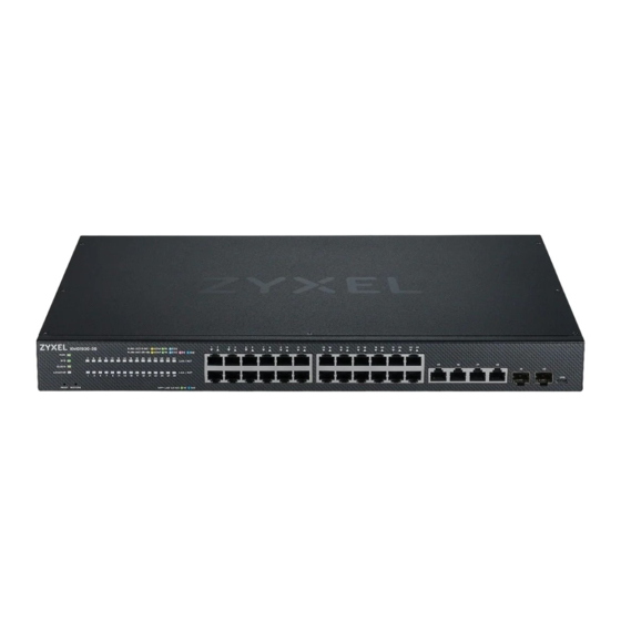
This chapter describes the front panel and rear panel of the Switch and shows you how to make the hardware connections. 3.1 Front Panel Connections The following figures show the front panels of the Switch. Figure 12 Front Panel: XMG1930-30 Figure 13 Front Panel: XMG1930-30HP The following table describes the ports. Table 8 Front Panel Connections... -
Page 46: Multi-Gigabit Ethernet Ports
Chapter 3 Hardware Panels Table 8 Front Panel Connections (continued) CONNECTOR DESCRIPTION 1G, 10G SFP+ Slots Use SFP+ transceivers in these ports for high-bandwidth backbone connections. You can also insert an SFP+ Direct Attach Copper (DAC) in the SFP+ slot. Port 29 –... -
Page 47: Poe (Xmg1930-30Hp)
3.1.1.2 Auto-crossover All ports support auto-crossover, that is auto-MDIX ports (Media Dependent Interface Crossover), so you may use either a straight-through Ethernet cable or crossover Ethernet cable for all Gigabit port connections. Auto-crossover ports automatically sense whether they need to function as crossover or straight ports, so crossover cables can connect both computers and switches or hubs. - Page 48 Chapter 3 Hardware Panels Press the transceiver firmly until it clicks into place. The Switch automatically detects the installed transceiver. Check the LEDs to verify that it is functioning properly. Remove the dust plugs from the transceiver and cables (dust plug styles vary). Identify the signal transmission direction of the fiber optic cables and the transceiver.
-
Page 49: Usb Port
Type C console cable) if you want to configure the Switch using the command line interface (CLI) through the console port. 3.2 Rear Panel The following figures show the rear panels of the Switch. The rear panels contain: Figure 20 Rear Panel: XMG1930-30 Figure 21 Rear Panel: XMG1930-30HP XMG1930 Series User’s Guide... -
Page 50: Grounding
Chapter 3 Hardware Panels 3.2.1 Grounding Grounding is a safety measure to direct excess electric charge to the ground. It prevents damage to the Switch, and protects you from electrocution. Use the grounding screw on the rear panel and the ground wire of the AC power supply to ground the Switch. -
Page 51: Ac Power Connection
Chapter 3 Hardware Panels The grounding terminal of the server rack or on-site grounding terminal must also be grounded and connected to the building’s main grounding electrode. Make sure the grounding terminal is connected to the buildings grounding electrode and has an earth resistance of less than 10 ohms, or according to your country’s electrical regulations. - Page 52 Chapter 3 Hardware Panels Push the pronged-end of the retainer clip into the Retainer Holder hole until it locks into place. Slide the clip up to the end of the power cord. Close the clip tightly around the power cord until secure. XMG1930 Series User’s Guide...
- Page 53 Chapter 3 Hardware Panels XMG1930 Series User’s Guide...
-
Page 54: Leds
Chapter 3 Hardware Panels 3.3 LEDs After you connect the power to the Switch, view the LEDs to ensure proper functioning of the Switch and as an aid in troubleshooting. Table 9 LED Descriptions COLOR STATUS DESCRIPTION Green The Switch is receiving power from the power source. Blinking The Switch is returning to the custom default configuration settings. - Page 55 The link to a 2.5G Ethernet network is up. Blinking The Switch is transmitting/receiving to/from a 2.5G Ethernet 1 – 24 network. (XMG1930-30 / Green The link to a 1000M Ethernet network is up. XMG1930-30HP) Blinking The Switch is transmitting/receiving to/from a 1000M Ethernet network.
- Page 56 Green The port has a successful 1000M connection. Blinking The port is transmitting or receiving data at 1000M. 29 – 30 (XMG1930-30 / Blue The port has a successful 10G connection. XMG1930-30HP) Blinking The port is transmitting or receiving data at 10G.
-
Page 57: Technical Reference
Technical Reference... -
Page 58: Web Configurator
H A P T E R Web Configurator 4.1 Overview This section introduces the configuration and functions of the Web Configurator. The Web Configurator is an HTML-based management interface that allows easy system setup and management through Internet browser. Use a browser that supports HTML5, such as Microsoft Edge, Mozilla Firefox, or Google Chrome. - Page 59 Chapter 4 Web Configurator Figure 25 Web Configurator: Login Click the Visit Nebula button if you want to open the Zyxel Nebula Control Center (NCC) login page in a new tab or window. The NCC is a cloud-based network management system that allows you to remotely manage and monitor the Switch.
- Page 60 Chapter 4 Web Configurator Figure 27 Select Mode Select the Web Configurator in Standard Mode that has a complete set of configuration for network installation. Or select the Web Configurator in Networked AV Mode that has a set of menus specifically designed to simplify configuration and management of the Switch for AVoIP (Audio-Video over Internet Protocol) application.
- Page 61 Chapter 4 Web Configurator Figure 28 Web Configurator: Wizard 11 If you did not change the default administrator password and/or SNMP community values, a warning screen displays each time you log into the Web Configurator and select Standard Mode. Click Password / SNMP to open a screen where you can change the administrator password and SNMP community string simultaneously.
- Page 62 Chapter 4 Web Configurator Figure 30 Web Configurator: Password/SNMP Note: The input string of any field in this screen should not contain [ ? ], [ | ], [ ' ], [ " ], or [ , ]. In the Password fields, [ space ] is also not allowed. Change the default administrator and/or SNMP passwords, and then click Apply to save your changes.
-
Page 63: Zyxel One Network (Zon) Utility
Chapter 4 Web Configurator 4.3 Zyxel One Network (ZON) Utility ZON Utility is a program designed to help you deploy and manage a network more efficiently. It detects devices automatically and allows you to do basic settings on devices in the network without having to be near it. - Page 64 Chapter 4 Web Configurator Figure 31 Supported Devices and Versions If you want to check the supported models and firmware versions later, you can click the Show information about ZON icon in the upper right of the screen. Then select the Supported model and firmware version link.
- Page 65 Chapter 4 Web Configurator Figure 33 Network Adapter Click the Go button for the ZON Utility to discover all supported devices in your network. Figure 34 Discovery The ZON Utility screen shows the devices discovered. Figure 35 ZON Utility Screen Select a device and then use the icons to perform actions.
- Page 66 Chapter 4 Web Configurator Figure 36 Password Prompt The following table describes the icons numbered from left to right in the ZON Utility screen. Table 11 ZON Utility Icons ICON DESCRIPTION 1 IP Configuration Change the selected device’s IP address. 2 Renew IP Address Update a DHCP-assigned dynamic IP address.
-
Page 67: Networked Av Mode Wizard
Chapter 4 Web Configurator Table 12 ZON Utility Fields (continued) LABEL DESCRIPTION IP Address This field displays the IP address of an internal interface on the discovered device that first received a ZDP discovery request from the ZON Utility. System Name This field displays the system name of the discovered device. - Page 68 Chapter 4 Web Configurator Figure 38 Wizard > Basic Settings > Step 1 IP Each field is described in the following table. Table 13 Wizard > Basic Settings > Step 1 IP LABEL DESCRIPTION Host Name This field displays a host name. IP Interface Select DHCP Client if the Switch is connected to a router with the DHCP server enabled.
- Page 69 Chapter 4 Web Configurator Figure 39 Wizard > Basic Settings > Step 2 Password Note: The input string of any field in this screen should not contain [ ? ], [ | ], [ ' ], [ " ], or [ , ]. In the Password fields, [ space ] is also not allowed.
- Page 70 Chapter 4 Web Configurator Table 14 Wizard > Basic Settings > Step 2 Password (continued) LABEL DESCRIPTION Trap Community Enter the Trap Community string, which is the password sent with each trap to the SNMP manager. The Trap Community string is only used by SNMP managers using SNMP version 2c or lower. Previous Click Previous to show the previous screen.
- Page 71 Chapter 4 Web Configurator Figure 41 Wizard > Basic Settings > Step 4 Summary Each field is described in the following table. Table 16 Wizard > Basic Settings > Step 4 Summary LABEL DESCRIPTION Setup IP Host Name This field displays a host name. IP Interface This field displays whether the WAN interface is using a DHCP IP address or a static IP address.
-
Page 72: Advanced Settings
Chapter 4 Web Configurator Table 16 Wizard > Basic Settings > Step 4 Summary (continued) LABEL DESCRIPTION Networked AV This field displays the Switch’s IP address for it to be managed over the AVoIP network. VLAN IP IGMP Snooping This field displays Active when IGMP Snooping is enabled to forward group multicast traffic only to ports that are members of that group. - Page 73 Chapter 4 Web Configurator Figure 42 Wizard > Advanced Settings > Step 1 IP Each field is described in the following table. Table 17 Wizard > Advanced Settings > Step 1 IP LABEL DESCRIPTION Host Name This field displays a host name. You can enter a new host name here.
- Page 74 Chapter 4 Web Configurator Figure 43 Wizard > Advanced Settings > Step 2 Password Note: The input string of any field in this screen should not contain [ ? ], [ | ], [ ' ], [ " ], or [ , ]. In the Password fields, [ space ] is also not allowed.
- Page 75 Chapter 4 Web Configurator Table 18 Wizard > Advanced Settings > Step 2 Password (continued) LABEL DESCRIPTION Trap Community Enter the Trap Community string, which is the password sent with each trap to the SNMP manager. The Trap Community string is only used by SNMP managers using SNMP version 2c or lower. Previous Click Previous to show the previous screen.
- Page 76 Chapter 4 Web Configurator Table 19 Wizard > Advanced Settings > Step 3 Networked AV (continued) LABEL DESCRIPTION Select all ports After you create a VLAN, select the ports to be assigned to the Networked AV VLAN. Select all ports to assign the same role to all ports. You can select a port by clicking it.
-
Page 77: Wizard
Chapter 4 Web Configurator Table 20 Wizard > Advanced Settings > Step 4 Summary (continued) LABEL DESCRIPTION This field displays the VLAN ID. IP Address This field displays the Switches’ IP address for it to be managed over the network. IP Subnet Mask This field displays the subnet mask that specifies the network number portion of an IP address. -
Page 78: Basic
Chapter 4 Web Configurator • Protection to enable loop guard and broadcast storm control on the Switch and its ports. – • VLAN to create a static VLAN, assign ports to the VLAN and set the ports to tag or untag outgoing –... - Page 79 Chapter 4 Web Configurator Figure 47 Wizard > Basic > Step 1 IP Each field is described in the following table. Table 21 Wizard > Basic > Step 1 IP LABEL DESCRIPTION Host Name This field displays a host name. Enter a string to set a new host name. The host name should not contain [ ? ], [ | ], [ ' ], [ "...
- Page 80 Chapter 4 Web Configurator Figure 48 Wizard > Basic > Step 2 Password Note: The input string of any field in this screen should not contain [ ? ], [ | ], [ ' ], [ " ], or [ , ]. In the Password fields, [ space ] is also not allowed.
- Page 81 Chapter 4 Web Configurator Table 22 Wizard > Basic > Step 2 Password (continued) LABEL DESCRIPTION Trap Community Enter the Trap Community string, which is the password sent with each trap to the SNMP manager. The Trap Community string is only used by SNMP managers using SNMP version 2c or lower. Previous Click Previous to show the previous screen.
- Page 82 Figure 50 Wizard > Basic > Step 4 Summary Each field is described in the following table. Table 24 Wizard > Basic > Step 4 Summary LABEL DESCRIPTION Setup IP Host Name This field displays a host name. IP Interface This field displays whether the WAN interface is using a DHCP IP address or a static IP address.
-
Page 83: Protection
Chapter 4 Web Configurator Table 24 Wizard > Basic > Step 4 Summary (continued) LABEL DESCRIPTION Previous Click Previous to show the previous screen. Finish Review the information and click Finish to create the task. Cancel Click Cancel to exit this screen without saving. 4.5.2 Protection In Protection, you can set up loop guard and broadcast storm control. - Page 84 Chapter 4 Web Configurator Figure 52 Wizard > Protection > Step 2 Broadcast Storm Control Each field is described in the following table. Table 26 Wizard > Protection > Step 2 Broadcast Storm Control LABEL DESCRIPTION Broadcast Storm Control Select all ports Select all ports to apply settings on all ports.
-
Page 85: Vlan
Chapter 4 Web Configurator Figure 53 Wizard > Protection > Step 3 Summary Each field is described in the following table. Table 27 Wizard > Protection > Step 3 Summary LABEL DESCRIPTION Summary Loop Guard If the loop guard feature is enabled on a port, the Switch will prevent loops on this port. Broadcast Storm If the broadcast storm control feature is enabled on a port, the number of broadcast Control... -
Page 86: Qos
Figure 54 Wizard > VLAN > VLAN Setting Each field is described in the following table. Table 28 Wizard > VLAN > VLAN Setting LABEL DESCRIPTION VLAN Setting Default VLAN 1 / After you create a VLAN and select the VLAN ID from the drop-down list box, select ports Access Untagged and use the right arrow to add them as the untagged ports to a VLAN group. -
Page 87: Web Configurator Layout
Chapter 4 Web Configurator Figure 55 Wizard > QoS > QoS Setting Each field is described in the following table. Table 29 Wizard > QoS > QoS Setting LABEL DESCRIPTION QoS Setting Select all ports Select all ports to apply settings on all ports. You can select a port by clicking it. - Page 88 Chapter 4 Web Configurator This guide uses the XMG1930-30HP screens as examples. The screens may vary slightly for different models. The following figure shows the navigating components of a Web Configurator screen. Figure 56 Web Configurator Layout (Without Access L3 License) Figure 57 Web Configurator Layout (With Access L3 License) Click the menu items to open sub-menu links, and then click on a sub-menu link to open the screen –...
- Page 89 Chapter 4 Web Configurator Click this icon to switch between the Web Configurator’s Standard or Networked AV mode (with – Access L3 license only). Click this icon to go to the NCC (Nebula Control Center) portal website. – C/D – Click this icon to search for specific configurations or status you are looking for. Enter the keywords and click the result link.
- Page 90 Chapter 4 Web Configurator Table 30 Navigation Panel Links (Standard Mode) (continued) LINK DESCRIPTION IPv4 This link takes you to a screen where you can view the IPv4 routing table for routing information Routing including IP interface and hop count to certain network destinations. Table IPv6 This link takes you to a screen where you can view the IPv6 routing table for routing information...
- Page 91 Chapter 4 Web Configurator Table 30 Navigation Panel Links (Standard Mode) (continued) LINK DESCRIPTION PORT Auto PD This link takes you to a screen where you can enable and configure Auto PD Recovery on the Recovery Switch. Flex Link This screen takes you to a screen where you can view configure backup links in the Data Link layer.
- Page 92 Chapter 4 Web Configurator Table 30 Navigation Panel Links (Standard Mode) (continued) LINK DESCRIPTION Diffserv This link takes you to screens where you can enable DiffServ, configure marking rules and set DSCP-to-IEEE802.1p mappings. Queuing This link takes you to a screen where you can set priorities for the queues of the Switch. This distrib- Method utes bandwidth across the different traffic queues.
- Page 93 Table 30 Navigation Panel Links (Standard Mode) (continued) LINK DESCRIPTION VLAN Isolation This link takes you to a screen where you can block traffic between ports in a VLAN on the Switch. VLAN Mapping This link takes you to screens where you can configure VLAN mapping settings on the Switch. VLAN Stacking This link takes you to screens where you can activate and configure VLAN stacking.
- Page 94 Chapter 4 Web Configurator Table 30 Navigation Panel Links (Standard Mode) (continued) LINK DESCRIPTION Errdisable This link takes you to a screens where you can view errdisable status and configure errdisable set- tings in CPU protection, errdisable detect, and errdisable recovery. IPv4 Source Click the link to unfold the following sub-link menu.
- Page 95 Chapter 4 Web Configurator Table 30 Navigation Panel Links (Standard Mode) (continued) LINK DESCRIPTION Erase This link takes you to a screen where you can reset the configuration to the Zyxel default configu- Running- ration settings. Configurati Save This link takes you to a screen where you can save the current configuration (settings) to a spe- Configurati cific configuration file on the Switch.
-
Page 96: Tables And Lists
Chapter 4 Web Configurator Table 31 Navigation Panel Links (Networked AV Mode) (continued) LINK DESCRIPTION Port Setup This screen allows you to configure settings for individual Switch ports. SWITCHING Mirroring This link takes you to screens where you can copy traffic from one port or ports to another port in order that you can examine the traffic from the first port without interference. -
Page 97: Change Your Password
Chapter 4 Web Configurator Figure 58 Working with a Table The following table describes the most common table icons. Table 32 Common Table Icons LABEL DESCRIPTION Select an entry’s check box to select a specific entry. Otherwise, select the check box in the table heading row to select all entries. -
Page 98: Save Your Configuration
Chapter 4 Web Configurator Figure 60 Change Administrator Login Password 4.7 Save Your Configuration When you are done modifying the settings in a screen, click Apply to save your changes back to the run-time memory. Settings in the run-time memory are lost when the Switch’s power is turned off. Click the Save link in the upper right of the Web Configurator to save your configuration to non-volatile memory. -
Page 99: Reset The Switch
Chapter 4 Web Configurator Forget the password and/or IP address. Prevent all services from accessing the Switch. Change a service port number but forget it. You forgot to log out of the Switch from a computer before logging in again on another computer. Note: Be careful not to lock yourself and others out of the Switch. - Page 100 Chapter 4 Web Configurator Click the Help icon on a Web Configurator screen to view an online help description (shown as below) of that screen. Figure 62 Online Web Help XMG1930 Series User’s Guide...
-
Page 101: Initial Setup Example
Chapter 5 Initial Setup Example H A P T E R Initial Setup Example 5.1 Overview This chapter shows how to set up the Switch for an example network. The following lists the configuration steps for the initial setup: • Create a VLAN •... -
Page 102: Set Port Vid
Chapter 5 Initial Setup Example The following screen appears. Click the switch to set this VLAN to Active, enter a descriptive name in the Name field and enter “2” in the VLAN Group ID field for the VLAN2 network. Note: The VLAN Group ID field in this screen and the VID field in the SYSTEM > IP Setup > IP Status screen refer to the same VLAN ID. -
Page 103: Configure Switch Management Ip Address
Chapter 5 Initial Setup Example that port get sent to VLAN 2. Figure 64 Initial Setup Network Example: Port VID Go to the SWITCHING > VLAN > VLAN Setup > VLAN Port Setup screen. Enter 2 in the PVID field for port 1 and click Apply to save your changes back to the run-time memory. Settings in the run-time memory are lost when the Switch’s power is turned off. - Page 104 Chapter 5 Initial Setup Example Figure 65 Initial Setup Example: Management IP Address Connect your computer to any Ethernet port on the Switch. Make sure your computer is in the same subnet as the Switch. Open your web browser and enter “setup.zyxel” or “192.168.1.1” (the default IP address) in the address bar to access the Web Configurator.
- Page 105 Chapter 5 Initial Setup Example For the VLAN2 network, enter 192.168.2.1 as the IP address and 255.255.255.0 as the subnet mask. In the VID field, enter the ID of the VLAN group to which you want this management IP address to belong.
-
Page 106: Tutorials
Chapter 6 Tutorials H A P T E R Tutorials 6.1 Overview This chapter provides some examples of using the Web Configurator to set up and use the Switch. The tutorials include: • How to Use DHCPv4 Snooping on the Switch •... - Page 107 Chapter 6 Tutorials Connect your computer to the out-of-band management port (So you can access the Switch without affected by any IP change caused by configurations). Access the Switch through http://192.168.0.1. Access the Switch through http://192.168.1.1 by default. Log into the Switch by entering the user name (default: admin) and password (default: 1234).
- Page 108 Chapter 6 Tutorials Tutorial: Tag Untagged Frames Go to SECURITY > IPv4 Source Guard > DHCP Snooping > DHCP Snp. Setup, activate and specify VLAN 100 as the DHCP VLAN as shown. Click Apply. IP requests from VLANs you enable on the SECURITY > IPv4 Source Guard > DHCP Snooping > DHCP Snp. VLAN Setup screen will be broadcast to the DHCP VLAN you set on this screen, which is VLAN100 in this example.
- Page 109 Chapter 6 Tutorials Go to SECURITY > IPv4 Source Guard > DHCP Snooping > DHCP Snp. VLAN Setup, show VLAN 100 by entering 100 in the VLAN Search by VID field and click Search. Select Yes in the Enabled field of the VLAN 100 entry shown in the search result. Click Apply. This enables DHCP snooping on VLAN100 (and other VLANs you enabled on this screen).
-
Page 110: How To Use Dhcpv4 Relay On The Switch
Chapter 6 Tutorials You can also use telnet. Use the command “show dhcp snooping binding” to see the DHCP snooping binding table as shown next. sysname# show dhcp snooping binding MacAddress IpAddress Lease Type VLAN Port ----------------- --------------- ------------ ------------- ---- ----- 88:88:88:88:88:8b... - Page 111 Chapter 6 Tutorials Go to SWITCHING > VLAN > VLAN Setup > Static VLAN. Click Add/Edit. The following screen appears. Enable the switch button to set this VLAN to Active. Enter a descriptive name (VLAN 102 for example) in the Name field and enter “102” in the VLAN Group ID field. XMG1930 Series User’s Guide...
- Page 112 Chapter 6 Tutorials Set port 2 to be a permanent member of this VLAN by selecting Fixed in the Control field. Clear the Tx Tagging check box to set the Switch to remove VLAN tags before sending. Click Apply to save the settings to the run-time memory. Settings in the run-time memory are lost when the Switch’s power is turned off.
-
Page 113: Configure Dhcpv4 Relay
Chapter 6 Tutorials Click Apply to save your changes back to the run-time memory. 10 Click the Save link in the upper right of the Web Configurator to save your configuration permanently. 6.3.3 Configure DHCPv4 Relay Follow the steps below to enable DHCP relay on the Switch and allow the Switch to add relay agent information (such as the VLAN ID) to DHCP requests. -
Page 114: Troubleshooting
Chapter 6 Tutorials 6.3.4 Troubleshooting Check client A’s IP address. If it did not receive the IP address 172.16.1.18, make sure: Client A is connected to the Switch’s port 2 in VLAN 102. You configured the correct VLAN ID, port number and system name for DHCP relay on both the DHCP server and the Switch. - Page 115 Chapter 6 Tutorials Setting Up the Switch Open the Web Configurator. Go to the MAINTENANCE > Configuration > Auto Configuration screen. Enable the switch button in the Active field to enable auto configuration. Select DHCP in the Mode field and click Apply to save your changes. Enable the switch button in the Active field to enable auto configuration.
- Page 116 Chapter 6 Tutorials You need to save the current configuration in a configuration file, so the Switch will load the auto configuration file from the TFTP server automatically when rebooting. Go to the MAINTENANCE > Configuration > Save Configuration screen. Click the Config 1, Config 2, or Custom Default button. Click the same button in the MAINTENANCE >...
- Page 117 Chapter 6 Tutorials 10 Check the screens to see if it is the configuration file you want to load. If it is not, go through the steps above to check your configurations. If it is, click Save at the top right corner of the Web Configurator to save the configuration permanently.
-
Page 118: Dashboard
H A P T E R DASHBOARD This chapter gives a quick introduction on the DASHBOARD screen. The DASHBOARD screen automatically appears after you log into the Web Configurator. 7.1 New User Interface With ZyNOS 4.80 and later, the Web Configurator’s user interface is restructured. In the new DASHBOARD screen, you can easily monitor the system status with the following tools (see DASHBOARD for more... - Page 119 Chapter 7 DASHBOARD Figure 68 DASHBOARD (example PoE model) The following table describes the labels in this screen. Table 34 DASHBOARD LABEL DESCRIPTION Pause Auto The DASHBOARD screen automatically refreshes every 30 seconds. Refresh Click this to disable the auto refresh. Click Resume Auto Refresh to enable. Port Status This displays individual port type, status, and connection speed of the Switch.
- Page 120 Chapter 7 DASHBOARD Table 34 DASHBOARD (continued) LABEL DESCRIPTION Registration This is the MAC address reserved for NCC registration. Use this MAC address to register the Switch on NCC. Address Cloud Control This field displays: Status • The Switch Internet connection status. •...
-
Page 121: Port Status
Chapter 7 DASHBOARD Table 34 DASHBOARD (continued) LABEL DESCRIPTION Temperature The Switch has temperature sensors that are capable of detecting and reporting if the temperature rises above the threshold. This displays the Switch’s current device temperature level. Click to go to the MONITOR > System Information screen to check the detailed information. Each fan of the Switch has a sensor that is capable of detecting and reporting if the fan speed falls below the threshold. -
Page 122: Quick Links To Use
Chapter 7 DASHBOARD 7.2.2 Quick Links to Use The quick links in the Quick Link section provide shortcuts to specific configuration screens. You can use the quick links to directly access the screens that you would frequently use. You can also decide which quick links to be put on the DASHBOARD screen using the Edit button. - Page 123 Chapter 7 DASHBOARD Figure 73 Quick Link Selection (example PoE model – with Access L3 license) Select the quick links you want and click Apply. The selected quick links will be displayed in the Quick Link section on the DASHBOARD screen. XMG1930 Series User’s Guide...
-
Page 124: Monitor
Chapter 8 MONITOR H A P T E R MONITOR The following chapters introduces the configurations of the links under the MONITOR navigation panel. Quick links to chapters: • ARP Table • IP Table • IPv6 Neighbor Table • MAC Table •... -
Page 125: Arp Table
Chapter 9 ARP Table H A P T E R ARP Table 9.1 ARP Table Overview This chapter introduces the ARP Table. Address Resolution Protocol (ARP) is a protocol for mapping an Internet Protocol address (IP address) to a physical machine address, also known as a Media Access Control or MAC address, on the local area network. - Page 126 Chapter 9 ARP Table Figure 74 MONITOR > ARP Table The following table describes the labels in this screen. Table 35 MONITOR > ARP Table LABEL DESCRIPTION Condition Specify how you want the Switch to remove ARP entries when you click Flush. Select All to remove all of the dynamic entries from the ARP table.
-
Page 127: Ip Table
Chapter 10 IP Table H A P T E R IP Table This chapter introduces the IP table screen. 10.1 IP Table Overview The IP Table screen shows how packets are forwarded or filtered across the Switch’s ports. When a device (which may belong to a VLAN group) sends a packet which is forwarded to a port on the Switch, the IP address of the device is shown on the Switch’s IP Table. -
Page 128: Viewing The Ip Table
Chapter 10 IP Table 10.2 Viewing the IP Table Click MONITOR > IP Table in the navigation panel to display the following screen. Figure 76 MONITOR > IP Table The following table describes the labels in this screen. Table 36 MONITOR > IP Table LABEL DESCRIPTION Index... -
Page 129: Ipv6 Neighbor Table
Chapter 11 IPv6 Neighbor Table H A P T E R IPv6 Neighbor Table 11.1 IPv6 Neighbor Table Overview This chapter introduces the IPv6 neighbor table. An IPv6 host is required to have a neighbor table. If there is an address to be resolved or verified, the Switch sends out a neighbor solicitation message. - Page 130 Chapter 11 IPv6 Neighbor Table The following table describes the labels in this screen. Table 37 MONITOR > IPv6 Neighbor Table LABEL DESCRIPTION Index This field displays the index number of each entry in the table. Address This field displays the IPv6 address of the Switch or a neighboring device. This field displays the MAC address of the IPv6 interface on which the IPv6 address is configured or the MAC address of the neighboring device.
-
Page 131: Mac Table
Chapter 12 MAC Table H A P T E R MAC Table 12.1 MAC Table Overview This chapter introduces the MAC Table screen. The MAC Table screen (a MAC table is also known as a filtering database) shows how frames are forwarded or filtered across the Switch’s ports. -
Page 132: Viewing The Mac Table
Chapter 12 MAC Table Figure 78 MAC Table Flowchart 12.2 Viewing the MAC Table Use this screen to search specific MAC addresses. You can also directly add dynamic MAC addresses into the static MAC forwarding table or MAC filtering table from the MAC table using this screen. Click MONITOR >... - Page 133 Chapter 12 MAC Table The following table describes the labels in this screen. Table 38 MONITOR > MAC Table LABEL DESCRIPTION Condition Select one of the below search conditions and click Search to only display the data which matches the criteria you specified. Select All to display any entry in the MAC table of the Switch.
-
Page 134: Neighbor
Chapter 13 Neighbor H A P T E R Neighbor 13.1 Neighbor Overview The Neighbor screen allows you to view a summary and manage the Switch’s neighboring devices. It uses Layer Link Discovery Protocol (LLDP) to discover all neighbor devices connected to the Switch including non-Zyxel devices. -
Page 135: Neighbor Details
Chapter 13 Neighbor The following table describes the fields in the above screen. Table 39 MONITOR > Neighbor LABEL DESCRIPTION Port This shows the port of the Switch, on which the neighboring device is discovered. Port Name This shows the port description of the Switch. PD Health For PoE models. - Page 136 Chapter 13 Neighbor devices are offline. When the maximum number of neighboring device records per Ethernet port is reached, new device records automatically overwrite existing offline device records, starting with the oldest existing offline device record first. Click MONITOR > Neighbor > Neighbor Details to see the following screen. Figure 81 MONITOR >...
- Page 137 Chapter 13 Neighbor Table 40 MONITOR > Neighbor > Neighbor Details (continued) LABEL DESCRIPTION PoE Draw (W) For PoE models. This shows the consumption that the neighboring device connected to this port draws from the Switch. This allows you to plan and use within the power budget of the Switch. PWR Cycle Click the Cycle button to turn OFF the power of the neighbor device and turn it back ON again.
-
Page 138: Path Mtu Table
Chapter 14 Path MTU Table H A P T E R Path MTU Table 14.1 Path MTU Overview This chapter introduces the IPv6 Path MTU table. The largest size (in bytes) of a packet that can be transferred over a data link is called the Maximum Transmission Unit (MTU). -
Page 139: Port Status
Chapter 15 Port Status H A P T E R Port Status This chapter introduces the Port Status screens. 15.0.1 What You Can Do Use the Port Status screen (Section 15.1 on page 139) to view the port status of the Switch. Use the DDMI screen (Section 15.2 on page 143) to view the DDMI (Digital Diagnostics Monitoring... -
Page 140: Port Details
Chapter 15 Port Status The following table describes the labels in this screen. Table 42 MONITOR > Port Status LABEL DESCRIPTION Port This identifies the Ethernet port. Click a port number to display the Port Details screen. Name This is the name you assigned to this port in the PORT > Port Setup screen. Link This field displays the speed (such as 100M for 100 Mbps, 1G for 1000 Mbps or 1 Gbps, 2.5G for 2.5 Gbps, 5G for 5 Gbps, or 10G for 10 Gbps) and the duplex (F for full duplex). - Page 141 Chapter 15 Port Status Figure 84 MONITOR > Port Status > Port Details The following table describes the labels in this screen. Table 43 MONITOR > Port Status > Port Details LABEL DESCRIPTION Port Info Port NO. This field displays the port number you are viewing. Name This field displays the name of the port.
- Page 142 Chapter 15 Port Status Table 43 MONITOR > Port Status > Port Details (continued) LABEL DESCRIPTION This field shows the percentage of actual transmitted frames on this port as a percentage of the Utilization% Link speed. Rx kB/s This field shows the number of kilobytes per second received on this port. This field shows the percentage of actual received frames on this port as a percentage of the Link Utilization% speed.
-
Page 143: Ddmi
Chapter 15 Port Status Table 43 MONITOR > Port Status > Port Details (continued) LABEL DESCRIPTION 512 to This field shows the number of packets (including bad packets) received that were between 512 1023 and 1023 octets in length. 1024 to This field shows the number of packets (including bad packets) received that were between 1024 1518 and 1518 octets in length. - Page 144 Chapter 15 Port Status Click an index in the Port column in the DDMI screen to view current transceivers’ status. Figure 86 MONITOR > Port Status > DDMI > DDMI Details The following table describes the labels in this screen. Table 45 MONITOR >...
-
Page 145: Port Utilization
Chapter 15 Port Status Table 45 MONITOR > Port Status > DDMI > DDMI Details (continued) LABEL DESCRIPTION TX Bias (mA) This displays the milliamps (mA) being supplied to the SFP transceiver’s Laser Diode Transmitter. TX Power This displays the amount of power the SFP transceiver is transmitting. (dbm) RX Power This displays the amount of power the SFP transceiver is receiving from the fiber cable. - Page 146 Chapter 15 Port Status Table 46 MONITOR > Port Status > Port Utilization (continued) LABEL DESCRIPTION Tx Utilization% This field shows the percentage of actual transmitted frames on this port as a percentage of the Link speed. Rx kB/s This field shows the transmission speed of data received on this port in kilobytes per second. Rx Utilization% This field shows the percentage of actual received frames on this port as a percentage of the Link speed.
-
Page 147: Routing Table
Chapter 16 Routing Table H A P T E R Routing Table 16.1 Routing Table Overview This chapter introduces the IPv4/IPv6 routing tables. The IPv4/IPv6 routing tables record routing information of the best path to destinations where packets were forwarded. Use this table to check information like routing destination, gateway, interface IP addresses, hop count, and routing methods. -
Page 148: Ipv6 Routing Table
Chapter 16 Routing Table Table 47 MONITOR > Routing Table > IPv4 Routing Table (continued) LABEL DESCRIPTION Metric This field displays the cost of the route. Type This field displays the method used to learn the route. STATIC – added as a static entry. LOCAL –... -
Page 149: System Information
Chapter 17 System Information H A P T E R System Information 17.0.1 What You Can Do Use the System Information screen (Section 17.1 on page 149) to view general system information and hardware status of the Switch. 17.1 System Information In the navigation panel, click MONITOR >... - Page 150 Chapter 17 System Information The following table describes the labels in this screen. Table 49 MONITOR > System Information LABEL DESCRIPTION System Information System This displays the descriptive name of the Switch for identification purposes. Name Product This displays the product model of the Switch. Use this information when searching for firmware Model upgrade or looking for other support information in the website.
- Page 151 Chapter 17 System Information Table 49 MONITOR > System Information (continued) LABEL DESCRIPTION Current This is the current voltage reading. This field displays the maximum voltage measured at this point. This field displays the minimum voltage measured at this point. Threshold This field displays the percentage tolerance of the voltage with which the Switch still works.
-
Page 152: System Log
Chapter 18 System Log H A P T E R System Log 18.1 System Log Overview A log message stores the system history information for viewing. 18.2 System Log Click MONITOR > System Log in the navigation panel to open this screen. Use this screen to check current system logs. - Page 153 Chapter 18 System Log The summary table shows the time the log message was recorded and the reason the log message was generated. Click Refresh to update this screen. Click Clear to clear the whole log, regardless of what is currently displayed on the screen.
-
Page 154: System
H A P T E R SYSTEM The following chapters introduces the configurations of the links under the SYSTEM navigation panel. Quick links to chapters: • Cloud Management • General Setup • Hardware Monitor Setup • Interface Setup • IP Setup •... -
Page 155: Cloud Management
Chapter 20 Cloud Management H A P T E R Cloud Management 20.1 Cloud Management Overview The Zyxel Nebula Control Center (NCC) is a cloud-based network management system that allows you to remotely manage and monitor Zyxel Nebula APs, Ethernet switches and security gateways. The Switch is managed and provisioned automatically by the NCC (Nebula Control Center) when: •... - Page 156 Chapter 20 Cloud Management Figure 92 SYSTEM > Cloud Management XMG1930 Series User’s Guide...
- Page 157 Chapter 20 Cloud Management The following table describes the labels in this screen. Table 50 SYSTEM > Cloud Management LABEL DESCRIPTION Nebula Control Enable the switch button to turn on Nebula Control Center (NCC) discovery on the Switch. Center (NCC) This field displays: Discovery •...
- Page 158 Chapter 20 Cloud Management If Nebula Control Center (NCC) Discovery is disabled, the Switch will NOT discover the NCC and remain in Standalone mode. XMG1930 Series User’s Guide...
-
Page 159: General Setup
Chapter 21 General Setup H A P T E R General Setup 21.1 General Setup Use this screen to configure general settings such as the system name and time. Click SYSTEM > General Setup in the navigation panel to display the screen as shown. Figure 93 SYSTEM >... - Page 160 Chapter 21 General Setup Table 51 SYSTEM > General Setup (continued) LABEL DESCRIPTION Use Time Server Enter the time service protocol that your time server uses. Not all time servers support all when Bootup protocols, so you may have to use trial and error to find a protocol that works. The main differences between them are the time format.
-
Page 161: Hardware Monitor Setup
Chapter 21 General Setup Table 51 SYSTEM > General Setup (continued) LABEL DESCRIPTION Apply Click Apply to save your changes to the Switch’s run-time memory. The Switch loses these changes if it is turned off or loses power, so use the Save link on the top navigation panel to save your changes to the non-volatile memory when you are done configuring. - Page 162 Chapter 21 General Setup You will see SFP warning icons next to the FANs in the MONITOR > System Information screen when SFP Detect has triggered the fans. Figure 95 Hardware Monitor: SFP Module Temperature Warning XMG1930 Series User’s Guide...
-
Page 163: Interface Setup
Chapter 22 Interface Setup H A P T E R Interface Setup 22.1 Interface Setup Overview This chapter shows you how to create virtual interfaces for interface-based configurations. An IPv6 address is configured on a per-interface basis. The interface can be a physical interface (for example, an Ethernet port) or a virtual interface (for example, a VLAN). -
Page 164: Add/Edit Interfaces
Chapter 22 Interface Setup 22.2.1 Add/Edit Interfaces Click Add/Edit, or select an entry and click Add/Edit in the SYSTEM > Interface Setup screen to display the configuration screen. Figure 97 SYSTEM > Interface Setup > Add/Edit The following table describes the labels in this screen. Table 54 SYSTEM >... -
Page 165: Ip Setup
Chapter 23 IP Setup H A P T E R IP Setup 23.1 IP Setup Overview This chapter shows you how to configure IP settings and set up IP interfaces on the Switch using the IP Setup screens. 23.1.1 What You Can Do •... -
Page 166: Ip Status Details
Chapter 23 IP Setup Figure 98 SYSTEM > IP Setup > IP Status The following table describes the labels in this screen. Table 55 SYSTEM > IP Setup > IP Status LABEL DESCRIPTION Domain Name Server Domain Name This field displays the IP address of the DNS server. Server Source This field displays whether the DNS server address is configured manually (Static) or obtained... - Page 167 Chapter 23 IP Setup Figure 99 SYSTEM > IP Setup > IP Status > IP Status Details: Static The following table describes the labels in this screen. Table 56 SYSTEM > IP Setup > IP Status > IP Status Details: Static LABEL DESCRIPTION Type...
-
Page 168: Ip Setup
Chapter 23 IP Setup Table 57 SYSTEM > IP Setup > IP Status > IP Status Details: DHCP (continued) LABEL DESCRIPTION Lease Time This displays the length of time in seconds that this interface can use the current dynamic IP address from the DHCP server. -
Page 169: Add/Edit Ip Interfaces
Chapter 23 IP Setup Table 58 SYSTEM > IP Setup > IP Setup (continued) LABEL DESCRIPTION Apply Click Apply to save your changes to the Switch’s run-time memory. The Switch loses these changes if it is turned off or loses power, so use the Save link on the top navigation panel to save your changes to the non-volatile memory when you are done configuring. -
Page 170: Network Proxy Configuration
Chapter 23 IP Setup The following table describes the labels in this screen. Table 59 SYSTEM > IP Setup > IP Setup > Add/Edit LABEL DESCRIPTION DHCP Client Select this option if you have a DHCP server that can assign the Switch an IP address, subnet mask, a default gateway IP address and a domain name server IP address automatically. - Page 171 Chapter 23 IP Setup Figure 105 SYSTEM > IP Setup > Network Proxy Configuration The following table describes the labels in this screen. Table 60 SYSTEM > IP Setup > Network Proxy Configuration LABEL DESCRIPTION Active Enable the switch button to enable communication between the Switch and NCC through a proxy server.
-
Page 172: Ipv6
Chapter 24 IPv6 H A P T E R IPv6 24.1 IPv6 Overview This chapter introduces the IPv6 screens. 24.1.1 What You Can Do • Use the IPv6 Status screen (Section 24.2 on page 172) to view the IPv6 table and DNS server information. -
Page 173: Ipv6 Interface Status Details
Chapter 24 IPv6 Figure 106 SYSTEM > IPv6 > IPv6 Status The following table describes the labels in this screen. Table 61 SYSTEM > IPv6 > IPv6 Status LABEL DESCRIPTION Domain Name Server Domain Name This field displays the IP address of the DNS server. Server Source This field displays whether the DNS server address is configured manually (Static) or obtained... - Page 174 Chapter 24 IPv6 Figure 107 SYSTEM > IPv6 > IPv6 Status > IPv6 Interface Details The following table describes the labels in this screen. Table 62 SYSTEM > IPv6 > IPv6 Status > IPv6 Interface Details LABEL DESCRIPTION Static IPv6 Active This field displays whether the IPv6 interface is activated or not.
-
Page 175: Ipv6 Global Setup
Chapter 24 IPv6 Table 62 SYSTEM > IPv6 > IPv6 Status > IPv6 Interface Details (continued) LABEL DESCRIPTION Global This field displays the Switch’s global unicast address to identify this interface. Unicast Address Joined This field displays the IPv6 multicast addresses of groups the Switch’s interface joins. Group Address DHCPv6 Client Active... -
Page 176: Ipv6 Interface Setup
Chapter 24 IPv6 Figure 108 SYSTEM > IPv6 > IPv6 Global Setup The following table describes the labels in this screen. Table 63 SYSTEM > IPv6 > IPv6 Global Setup LABEL DESCRIPTION IPv6 Hop Limit Specify the maximum number of hops (from 1 to 255) in router advertisements. This is the maximum number of hops on which an IPv6 packet is allowed to transmit before it is discarded by an IPv6 router, which is similar to the TTL field in IPv4. -
Page 177: Edit An Ipv6 Interface
Chapter 24 IPv6 Table 64 SYSTEM > IPv6 > IPv6 Interface Setup (continued) LABEL DESCRIPTION Select an entry’s check box to select a specific entry. Edit Click Edit to edit the selected interface. 24.4.1 Edit an IPv6 Interface Use this screen to turn on or off an IPv6 interface you create in the SYSTEM > Interface Setup screen. Select an entry and click Edit in the SYSTEM >... -
Page 178: Edit An Ipv6 Link-Local Address
Chapter 24 IPv6 Figure 111 SYSTEM > IPv6 > IPv6 Addressing > IPv6 Link-Local Address Setup The following table describes the labels in this screen. Table 66 SYSTEM > IPv6 > IPv6 Addressing > IPv6 Link-Local Address Setup LABEL DESCRIPTION Index This is the interface index number. -
Page 179: Ipv6 Global Address Setup
Chapter 24 IPv6 24.6 IPv6 Global Address Setup Use this screen to view and configure the interface’s IPv6 global address. Click SYSTEM > IPv6 Addressing > IPv6 Global Address Setup to display the screen as shown next. Figure 113 SYSTEM > IPv6 > IPv6 Addressing > IPv6 Global Address Setup The following table describes the labels in this screen. -
Page 180: Ipv6 Neighbor Discovery Setup
Chapter 24 IPv6 Figure 114 SYSTEM > IPv6 > IPv6 Addressing > IPv6 Global Address Setup > Add/Edit The following table describes the labels in this screen. Table 69 SYSTEM > IPv6 > IPv6 Addressing > IPv6 Global Address Setup > Add/Edit LABEL DESCRIPTION Interface... -
Page 181: Edit An Ipv6 Neighbor Discovery
Chapter 24 IPv6 Table 70 SYSTEM > IPv6 > IPv6 Neighbor Discovery > IPv6 Neighbor Discovery Setup (continued) LABEL DESCRIPTION NS Interval This field displays the time interval (in milliseconds) at which neighbor solicitations are re-sent for this interface. Reachable This field displays how long (in milliseconds) a neighbor is considered reachable for this interface. -
Page 182: Ipv6 Router Discovery Setup
Chapter 24 IPv6 24.8 IPv6 Router Discovery Setup Use this screen to configure router discovery settings for each interface. Click SYSTEM > IPv6 > IPv6 Neighbor Discovery > IPv6 Router Discovery Setup to display the screen as shown next. Figure 117 SYSTEM > IPv6 > IPv6 Neighbor Discovery > IPv6 Router Discovery Setup The following table describes the labels in this screen. -
Page 183: Ipv6 Prefix Setup
Chapter 24 IPv6 Figure 118 SYSTEM > IPv6 > IPv6 Neighbor Discovery > IPv6 Router Discovery Setup > Edit The following table describes the labels in this screen. Table 73 SYSTEM > IPv6 > IPv6 Neighbor Discovery > IPv6 Router Discovery Setup > Edit LABEL DESCRIPTION Interface... -
Page 184: Add/Edit Ipv6 Prefix
Chapter 24 IPv6 Figure 119 SYSTEM > IPv6 > IPv6 Neighbor Discovery > IPv6 Prefix Setup The following table describes the labels in this screen. Table 74 SYSTEM > IPv6 > IPv6 Neighbor Discovery > IPv6 Prefix Setup LABEL DESCRIPTION Index This is the interface index number. -
Page 185: Ipv6 Neighbor Setup
Chapter 24 IPv6 Table 75 SYSTEM > IPv6 > IPv6 Neighbor Discovery > IPv6 Prefix Setup > Add/Edit (continued) LABEL DESCRIPTION Prefix Length Set the prefix length that the Switch includes in router advertisements for this interface. Valid Lifetime Specify how long (from 0 to 4294967295 seconds) the prefix is valid for on-link determination. -
Page 186: Add/Edit Ipv6 Neighbor
Chapter 24 IPv6 24.10.1 Add/Edit IPv6 Neighbor Use this screen to create a static IPv6 neighbor entry. Click Add/Edit, or select an entry and click Add/ Edit in the SYSTEM > IPv6 > IPv6 Neighbor Setup screen to display this screen. Figure 122 SYSTEM >... -
Page 187: Edit Dhcpv6 Client
Chapter 24 IPv6 Figure 123 SYSTEM > IPv6 > DHCPv6 Client Setup The following table describes the labels in this screen. Table 78 SYSTEM > IPv6 > DHCPv6 Client Setup LABEL DESCRIPTION Index This is the interface index number. Interface This is the name of the IPv6 interface you created. - Page 188 Chapter 24 IPv6 The following table describes the labels in this screen. Table 79 SYSTEM > IPv6 > DHCPv6 Client Setup > Edit LABEL DESCRIPTION Interface Select the IPv6 interface you want to configure. IA Type Select IA-NA to set the Switch to get a non-temporary IP address from the DHCPv6 server for this interface.
-
Page 189: Logins
Chapter 25 Logins H A P T E R Logins 25.1 Set Up Login Accounts Up to five people (one administrator and four non-administrators) may access the Switch through Web Configurator at any one time. • An administrator is someone who can both view and configure Switch changes. The user name for the Administrator is always admin. - Page 190 Chapter 25 Logins The following table describes the labels in this screen. Table 80 SYSTEM > Logins LABEL DESCRIPTION Administrator This is the default administrator account with the “admin” user name. You cannot change the default administrator user name. Old Password Type the existing system password (1234 is the default password when shipped).
-
Page 191: Snmp
Chapter 26 SNMP H A P T E R SNMP 26.1 SNMP Overview This chapter introduces the SNMP screens and shows you how to setup SNMP settings for management. 26.1.1 What You Can Do • Use the SNMP screen (Section 26.2 on page 191) to configure general SNMP settings. - Page 192 Chapter 26 SNMP Figure 126 SYSTEM > SNMP Note: The string of any field in this screen should not contain [ ? ], [ | ], [ ' ], [ " ] or [ , ]. The following table describes the labels in this screen. Table 81 SYSTEM >...
-
Page 193: Configure Snmp User
Chapter 26 SNMP Table 81 SYSTEM > SNMP (continued) LABEL DESCRIPTION Port Enter the port number upon which the manager listens for SNMP traps. Username Enter the user name to be sent to the SNMP manager along with the SNMP v3 trap. This user name must match an existing account on the Switch (configured in the SYSTEM >... - Page 194 Chapter 26 SNMP Note: Use the user name and password of the login accounts you specify in this screen to create accounts on the SNMP v3 manager. Figure 128 SYSTEM > SNMP > SNMP User > Add/Edit The following table describes the labels in this screen. Table 83 SYSTEM >...
-
Page 195: Snmp Trap Group
Chapter 26 SNMP Table 83 SYSTEM > SNMP > SNMP User > Add/Edit (continued) LABEL DESCRIPTION Apply Click Apply to save your changes to the Switch’s run-time memory. The Switch loses these changes if it is turned off or loses power, so use the Save link on the top navigation panel to save your changes to the non-volatile memory when you are done configuring. -
Page 196: Enable Or Disable Sending Of Snmp Traps On A Port
Chapter 26 SNMP The following table describes the labels in this screen. Table 84 SYSTEM > SNMP > SNMP Trap Group LABEL DESCRIPTION Trap Destination IP Select one of your configured trap destination IP addresses. These are the IP addresses of the SNMP managers. -
Page 197: Technical Reference
Chapter 26 SNMP The following table describes the labels in this screen. Table 85 SYSTEM > SNMP > SNMP Trap Port LABEL DESCRIPTION Options Select the trap type you want to configure here. Port This field displays a port number. Settings in this row apply to all ports. - Page 198 Chapter 26 SNMP SNMP. The manager is the console through which network administrators perform network management functions. It executes applications that control and monitor managed devices. The managed devices contain object variables or managed objects that define each piece of information to be collected about a Switch.
- Page 199 Chapter 26 SNMP Table 87 SNMP System Traps OPTION OBJECT LABEL OBJECT ID DESCRIPTION coldstart coldStart 1.3.6.1.6.3.1.1.5.1 This trap is sent when the Switch is turned on. warmstart warmStart 1.3.6.1.6.3.1.1.5.2 This trap is sent when the Switch restarts. fanspeed zyHwMonitorFanSpeedOutOfR 1.3.6.1.4.1.890.1.15 This trap is sent when the fan speed goes ange...
- Page 200 Chapter 26 SNMP Table 87 SNMP System Traps (continued) OPTION OBJECT LABEL OBJECT ID DESCRIPTION pethPsePortOnOffNotification 1.3.6.1.2.1.105.0.1 This trap is sent when the PoE port delivers power or delivers no power to a PD. (For PoE models pethMainPowerUsageOnNo 1.3.6.1.2.1.105.0.2 This trap is sent when the usage power is only) tification above the usage indication threshold.
- Page 201 Chapter 26 SNMP Table 88 SNMP Interface Traps (continued) OPTION OBJECT LABEL OBJECT ID DESCRIPTION transceiver- zyTransceiverDdmiTemperatur 1.3.6.1.4.1.890.1.15. This trap is sent when the transceiver eOutOfRange 3.84.3.1 temperature is above or below the normal operating range. zyTransceiverDdmiTxPowerOut 1.3.6.1.4.1.890.1.15. This trap is sent when the transmitted optical OfRange 3.84.3.2 power is above or below the normal...
- Page 202 Chapter 26 SNMP Table 89 SNMP AAA Traps OPTION OBJECT LABEL OBJECT ID DESCRIPTION authentication zyRadiusServerAuthenticationS 1.3.6.1.4.1.890.1.15 This trap is sent when there is no response erverNotReachable .3.71.2.1 message from the RADIUS authentication server. zyRadiusServerAuthenticationS 1.3.6.1.4.1.890.1.15 This trap is sent when there is a response erverNotReachableRecovered .3.71.2.3 message from the previously unreachable...
- Page 203 Chapter 26 SNMP Table 91 SNMP Switch Traps OPTION OBJECT LABEL OBJECT ID DESCRIPTION zyMrstpNewRoot 1.3.6.1.4.1.890.1.15 This trap is sent when the MRSTP root switch .3.52.3.1 changes. zyMstpNewRoot 1.3.6.1.4.1.890.1.15 This trap is sent when the MSTP root switch .3.53.3.1 changes. zyMrstpTopologyChange 1.3.6.1.4.1.890.1.15 This trap is sent when the MRSTP topology...
-
Page 204: Switch Setup
Chapter 27 Switch Setup H A P T E R Switch Setup 27.1 Switch Setup Overview Use this screen to do the Switch’s basic setup configuration, for example, VLAN (Virtual Local Area Network) type, enabling switching protocols, and MAC learning aging time setup. 27.1.1 Introduction to VLANs A VLAN (Virtual Local Area Network) allows a physical network to be partitioned into multiple logical networks. - Page 205 Chapter 27 Switch Setup Figure 133 Basic Setting > Switch Setup (Without Access L3 License) Figure 134 SYSTEM > Switch Setup (With Access L3 License) The following table describes the labels in this screen. Table 92 SYSTEM > Switch Setup LABEL DESCRIPTION VLAN Type...
- Page 206 Chapter 27 Switch Setup Table 92 SYSTEM > Switch Setup (continued) LABEL DESCRIPTION Aging Time Enter a time from 10 to 1000000 seconds. This is how long all dynamically learned MAC addresses remain in the MAC address table before they age out (and must be relearned). ARP Aging Time Aging Time Enter a time from 60 to 1000000 seconds.
-
Page 207: Syslog Setup
Chapter 28 Syslog Setup H A P T E R Syslog Setup 28.1 Syslog Overview This chapter explains the Syslog screens. The syslog protocol allows devices to send event notification messages across an IP network to syslog servers that collect the event messages. A syslog-enabled device can generate a syslog message and send it to a syslog server. - Page 208 Chapter 28 Syslog Setup Figure 135 SYSTEM > Syslog Setup The following table describes the labels in this screen. Table 94 SYSTEM > Syslog Setup LABEL DESCRIPTION Syslog Setup Active Enable the switch button to turn on syslog (system logging) and then configure the syslog setting.
-
Page 209: Add/Edit A Syslog Server
Chapter 28 Syslog Setup 28.2.1 Add/Edit a Syslog Server Use this screen to configure an external syslog server. Click Add/Edit, or select an entry and click Add/Edit in the SYSTEM > Syslog Setup screen to display this screen. Figure 136 SYSTEM > Syslog Setup > Add/Edit The following table describes the labels in this screen. -
Page 210: Time Range
Chapter 29 Time Range H A P T E R Time Range 29.1 Time Range Overview You can set up one-time and recurring schedules for time-oriented features, such as PoE and classifier. The UAG supports one-time and recurring schedules. One-time schedules are effective only once, while recurring schedules usually repeat. -
Page 211: Add/Edit Time Range
Chapter 29 Time Range The following table describes the labels in this screen. Table 96 SYSTEM > Time Range LABEL DESCRIPTION Select an entry’s check box to select a specific entry. Otherwise, select the check box in the table heading row to select all entries. Index This field displays the index number of the rule. - Page 212 Chapter 29 Time Range The following table describes the labels in this screen. Table 97 SYSTEM > Time Range > Add/Edit LABEL DESCRIPTION Name Enter a descriptive name for this rule for identifying purposes. The string should not contain [ ? ], [ | ], [ ' ], [ "...
-
Page 213: Port
H A P T E R PORT The following chapters introduces the configurations of the links under the PORT navigation panel. Quick links to chapters: • Auto PD Recovery (for PoE models only) • Flex Link • Green Ethernet • Link Aggregation •... -
Page 214: Auto Pd Recovery
Chapter 31 Auto PD Recovery H A P T E R Auto PD Recovery 31.1 Auto PD Recovery (for PoE models only) Overview Things can go wrong with any network devices. A PD (for example, IP camera) may slow down or freeze and need to be restarted if it is overworked or a bug causes a memory leak. - Page 215 Chapter 31 Auto PD Recovery To open this screen, click PORT > Auto PD Recovery. Figure 140 PORT > Auto PD Recovery The following table describes the labels in this screen. Table 98 PORT > Auto PD Recovery LABEL DESCRIPTION Active Select this option to enable Auto PD Recovery on the Switch.
-
Page 216: Activate The Automatic Pd Recovery
Chapter 31 Auto PD Recovery Table 98 PORT > Auto PD Recovery (continued) LABEL DESCRIPTION Polling Count Specify how many times the Switch is to resend a ping request before considering the PD unreachable. For example, If there is no ping reply from the PD after the Polling Interval (sec) has elapsed, Polling Count starts from 1. - Page 217 Chapter 31 Auto PD Recovery Figure 141 Auto PD Recovery (Ping Mode) Figure 142 Auto PD Recovery (LLDP Mode) Select the desired ports in the Active column. Select the Mode. When you select Ping, the connected PD’s IPv4 or IPv6 address to which the Switch sends ping requests will display automatically if the PD supports LLDP.
- Page 218 Chapter 31 Auto PD Recovery Once the LLDP table’s counter reaches the default 120 seconds, the Switch will cause a Reboot-Alarm on the PD as selected in Action. After sending an SNMP trap and generating a log message, the connected PD will restart (the connecting port is detected as link-down).
-
Page 219: Flex Link
Chapter 32 Flex Link H A P T E R Flex Link This chapter introduces how to set up a backup link for a primary link using Flex Links. 32.1 Flex Link Overview A flex link pair consists of a primary link and a backup link on a layer-2 interface. A primary link runs on a Primary Port;... -
Page 220: Flex Link Setup
Chapter 32 Flex Link The following table describes the labels in this screen. Table 99 PORT > Flex Link > Flex Link Status LABEL DESCRIPTION Index This displays the index number of a flex link pair. Primary Port This displays the port number of the primary link. Backup Port This displays the port number of the backup link. -
Page 221: Add/Edit Flex Link
Chapter 32 Flex Link Table 100 PORT > Flex Link > Flex Link Setup (continued) LABEL DESCRIPTION Select an entry’s check box to select a specific entry. Otherwise, select the check box in the table heading row to select all entries. Add/Edit Click Add/Edit to add a new entry or edit a selected one. -
Page 222: Green Ethernet
Chapter 33 Green Ethernet H A P T E R Green Ethernet This chapter shows you how to configure the Switch to reduce the power consumed by switch ports. 33.1 Green Ethernet Overview Green Ethernet reduces switch port power consumption in the following ways. IEEE 802.3az Energy Efficient Ethernet (EEE) If EEE is enabled, both sides of a link support EEE and there is no traffic, the port enters Low Power Idle (LPI) mode. - Page 223 Chapter 33 Green Ethernet Figure 146 PORT > Green Ethernet The following table describes the labels in this screen. Table 102 PORT > Green Ethernet LABEL DESCRIPTION Enable the switch button to activate Energy Efficient Ethernet globally. Auto Power Enable the switch button to activate Auto Power Down globally. Down Short Reach Enable the switch button to activate Short Reach globally.
-
Page 224: Link Aggregation
Chapter 34 Link Aggregation H A P T E R Link Aggregation 34.1 Link Aggregation Overview This chapter shows you how to logically aggregate physical links to form one logical, higher-bandwidth link. Link aggregation (trunking) is the grouping of physical ports into one logical higher-capacity link. You may want to trunk ports if for example, it is cheaper to use multiple lower-speed links than to under-utilize a high-speed, but more costly, single-port link. -
Page 225: Link Aggregation Status
Chapter 34 Link Aggregation operational port fails, then one of the “standby” ports become operational without user intervention. Please note that: • You must connect all ports point-to-point to the same Ethernet switch and configure the ports for LACP trunking. •... - Page 226 Chapter 34 Link Aggregation Figure 147 PORT > Link Aggregation > Link Aggregation Status The following table describes the labels in this screen. Table 105 PORT > Link Aggregation > Link Aggregation Status LABEL DESCRIPTION Group ID This field displays the group ID to identify a trunk group, that is, one logical link containing multiple ports.
-
Page 227: Link Aggregation Setting
Chapter 34 Link Aggregation 34.3 Link Aggregation Setting Click PORT > Link Aggregation > Link Aggregation Setting to display the screen shown next. See Section 34.1 on page 224 for more information on link aggregation. Figure 148 PORT > Link Aggregation > Link Aggregation Setting The following table describes the labels in this screen. -
Page 228: Link Aggregation Control Protocol
Chapter 34 Link Aggregation Table 106 PORT > Link Aggregation > Link Aggregation Setting (continued) LABEL DESCRIPTION Criteria Select the outgoing traffic distribution type. Packets from the same source and/or to the same destination are sent over the same link within the trunk. By default, the Switch uses the src-dst-mac distribution type. - Page 229 Chapter 34 Link Aggregation Figure 149 PORT > Link Aggregation > Link Aggregation Control Protocol The following table describes the labels in this screen. Table 107 PORT > Link Aggregation > Link Aggregation Control Protocol LABEL DESCRIPTION Active Enable the switch button to enable Link Aggregation Control Protocol (LACP). System Priority LACP system priority is a number between 1 and 65535.
-
Page 230: Technical Reference
Chapter 34 Link Aggregation Table 107 PORT > Link Aggregation > Link Aggregation Control Protocol (continued) LABEL DESCRIPTION Settings in this row apply to all ports. Use this row only if you want to make some settings the same for all ports. Use this row first to set the common settings and then make adjustments on a port-by-port basis. - Page 231 Chapter 34 Link Aggregation Figure 151 Trunking Example – Configuration Screen Your trunk group 1 (T1) configuration is now complete. XMG1930 Series User’s Guide...
-
Page 232: Link Layer Discovery Protocol (Lldp)
Chapter 35 Link Layer Discovery Protocol (LLDP) H A P T E R Link Layer Discovery Protocol (LLDP) 35.1 LLDP Overview The LLDP (Link Layer Discovery Protocol) is a layer 2 protocol. It allows a network device to advertise its identity and capabilities on the local network. -
Page 233: Lldp-Med Overview
Chapter 35 Link Layer Discovery Protocol (LLDP) The next figure demonstrates that the network devices Switches and Routers (S and R) transmit and receive device information through LLDPDU and the network manager can query the information using Simple Network Management Protocol (SNMP). Figure 152 LLDP Overview 35.2 LLDP-MED Overview LLDP-MED (Link Layer Discovery Protocol for Media Endpoint Devices) is an extension to the standard... -
Page 234: What You Can Do - Lldp
Chapter 35 Link Layer Discovery Protocol (LLDP) Figure 153 LLDP-MED Overview 35.2.1 What You Can Do – LLDP • Use the LLDP Local Status screen (Section 35.3 on page 234) to view the Switch’s LLDP information. • Use the LLDP Remote Status screen (Section 35.4 on page 239) to view LLDP information from the neighboring devices. - Page 235 Chapter 35 Link Layer Discovery Protocol (LLDP) Figure 154 PORT > LLDP > LLDP > LLDP Local Status The following table describes the labels in this screen. Table 108 PORT > LLDP > LLDP > LLDP Local Status LABEL DESCRIPTION Basic TLV Chassis ID TLV This displays the chassis ID of the local Switch, that is the Switch you are configuring.
-
Page 236: Lldp Local Port Status Detail
Chapter 35 Link Layer Discovery Protocol (LLDP) Table 108 PORT > LLDP > LLDP > LLDP Local Status (continued) LABEL DESCRIPTION Local Port This displays the number of the Switch port which receives the LLDPDU from the remote device. Click a port number to view the detailed LLDP status on this port in the LLDP Local Port Status Detail screen. - Page 237 Chapter 35 Link Layer Discovery Protocol (LLDP) Figure 155 PORT > LLDP > LLDP > LLDP Local Status > LLDP Local Port Status Detail XMG1930 Series User’s Guide...
- Page 238 Chapter 35 Link Layer Discovery Protocol (LLDP) The following table describes the labels in this screen. Table 109 PORT > LLDP > LLDP > LLDP Local Status > LLDP Local Port Status Detail LABEL DESCRIPTION Local Port This displays the number of the Switch’s port. Basic TLV These are the Basic TLV flags Port ID TLV...
-
Page 239: Lldp Remote Status
Chapter 35 Link Layer Discovery Protocol (LLDP) Table 109 PORT > LLDP > LLDP > LLDP Local Status > LLDP Local Port Status Detail (continued) LABEL DESCRIPTION Network Policy This displays a network policy for the specified application. • Voice •... -
Page 240: Lldp Remote Port Status Detail
Chapter 35 Link Layer Discovery Protocol (LLDP) Table 110 PORT > LLDP > LLDP > LLDP Remote Status (continued) LABEL DESCRIPTION Port Description This displays a description for the port from which this LLDPDU was transmitted. System Name This displays the system name of the remote device. Management This displays the management address of the remote device. - Page 241 Chapter 35 Link Layer Discovery Protocol (LLDP) Table 111 PORT > LLDP > LLDP > LLDP Remote Status > LLDP Remote Port Status Detail (Basic TLV) LABEL DESCRIPTION Port ID TLV • Port ID Subtype – This displays how the port of the remote device is identified. •...
- Page 242 Chapter 35 Link Layer Discovery Protocol (LLDP) Figure 158 PORT > LLDP > LLDP > LLDP Remote Status > LLDP Remote Port Status Detail (Dot1 and Dot3 TLV) The following table describes the labels in the Dot1 and Dot3 parts of the screen. Table 112 PORT >...
- Page 243 Chapter 35 Link Layer Discovery Protocol (LLDP) Table 112 PORT > LLDP > LLDP > LLDP Remote Status > LLDP Remote Port Status Detail (Dot1 and Dot3 TLV) (continued) LABEL DESCRIPTION MAC PHY The MAC/PHY Configuration/Status TLV advertises the bit-rate and duplex capability of the Configuration &...
- Page 244 Chapter 35 Link Layer Discovery Protocol (LLDP) Figure 159 PORT > LLDP > LLDP > LLDP Remote Status > LLDP Remote Port Status Detail (MED TLV) The following table describes the labels in the MED TLV part of the screen. Table 113 PORT >...
-
Page 245: Lldp Setup
Chapter 35 Link Layer Discovery Protocol (LLDP) Table 113 PORT > LLDP > LLDP > LLDP Remote Status > LLDP Remote Port Status Detail (MED TLV) LABEL DESCRIPTION Location This shows the location information of a caller by its: Identification •... - Page 246 Chapter 35 Link Layer Discovery Protocol (LLDP) Figure 160 PORT > LLDP > LLDP > LLDP Setup The following table describes the labels in this screen. Table 114 PORT > LLDP > LLDP > LLDP Setup LABEL DESCRIPTION Active Select to enable LLDP on the Switch. It is enabled by default. Transmit Interval Enter how many seconds the Switch waits before sending LLDP packets.
-
Page 247: Basic Tlv Setting
Chapter 35 Link Layer Discovery Protocol (LLDP) Table 114 PORT > LLDP > LLDP > LLDP Setup (continued) LABEL DESCRIPTION Admin Status Select whether LLDP transmission and/or reception is allowed on this port. • Disable – not allowed • Tx-Only – transmit only •... -
Page 248: Org-Specific Tlv Setting
Chapter 35 Link Layer Discovery Protocol (LLDP) Table 115 PORT > LLDP > LLDP > Basic TLV Setting (continued) LABEL DESCRIPTION System Capabilities Select the check boxes to enable or to disable the sending of System Capabilities TLVs on the ports. -
Page 249: Lldp-Med Setup
Chapter 35 Link Layer Discovery Protocol (LLDP) Table 116 PORT > LLDP > LLDP > Org-specific TLV Setting (continued) LABEL DESCRIPTION Port-Protocol Select the check boxes to enable or disable the sending of IEEE 802.1 Port and Protocol VLAN VLAN ID ID TLVs on the ports. -
Page 250: Lldp-Med Network Policy
Chapter 35 Link Layer Discovery Protocol (LLDP) The following table describes the labels in this screen. Table 117 PORT > LLDP > LLDP > LLDP-MED Setup LABEL DESCRIPTION Port This displays the Switch’s port number. Select * to configure all ports simultaneously. Use this row to make the setting the same for all ports. -
Page 251: Add/Edit Lldp-Med Network Policy
Chapter 35 Link Layer Discovery Protocol (LLDP) Table 118 PORT > LLDP > LLDP MED > LLDP-MED Network Policy (continued) LABEL DESCRIPTION Add/Edit Click Add/Edit to add a new schedule rule or edit a selected one. Delete Select the rules that you want to remove, then click Delete. 35.9.1 Add/Edit LLDP-MED Network Policy To access this screen, click the Add/Edit button or select an entry from the list and click the Add/Edit button. -
Page 252: Lldp-Med Location
Chapter 35 Link Layer Discovery Protocol (LLDP) Table 119 PORT > LLDP > LLDP MED > LLDP-MED Network Policy > Add/Edit (continued) LABEL DESCRIPTION Apply Click Apply to save your changes to the Switch’s run-time memory. The Switch loses these changes if it is turned off or loses power, so use the Save link on the top navigation panel to save your changes to the non-volatile memory when you are done configuring. - Page 253 Chapter 35 Link Layer Discovery Protocol (LLDP) Figure 167 PORT > LLDP > LLDP MED > LLDP-MED Location > Add/Edit The following table describes the labels in this screen. Table 121 PORT > LLDP > LLDP MED > LLDP-MED Location > Add/Edit LABEL DESCRIPTION Port...
- Page 254 Chapter 35 Link Layer Discovery Protocol (LLDP) Table 121 PORT > LLDP > LLDP MED > LLDP-MED Location > Add/Edit (continued) LABEL DESCRIPTION Longitude Enter the longitude information. The value should be from 0º to 180º. • west • east Altitude Enter the altitude information.
-
Page 255: Oam
Chapter 36 OAM H A P T E R 36.1 OAM Overview Link layer Ethernet OAM (Operations, Administration and Maintenance) as described in IEEE 802.3ah is a link monitoring protocol. It utilizes OAM Protocol Data Units or OAM PDUs to transmit link status information between directly connected Ethernet devices. -
Page 256: Oam Details
Chapter 36 OAM Figure 168 PORT > OAM > OAM Status The following table describes the fields in the above screen. Table 122 PORT > OAM > OAM Status LABEL DESCRIPTION Local This section displays information about the ports on the Switch. Port This field displays the port number. - Page 257 Chapter 36 OAM Figure 169 PORT > OAM > OAM Status > OAM Details The following table describes the fields in the above screen. Table 123 PORT > OAM > OAM Status > OAM Details LABEL DESCRIPTION Port No This field displays the port number. Discovery This section displays OAM configuration details and operational status of the port on the Switch and/or the remote device.
- Page 258 Chapter 36 OAM Table 123 PORT > OAM > OAM Status > OAM Details (continued) LABEL DESCRIPTION Local Client/Remote Client Setup Mode This field displays the OAM mode. The device in active mode (typically the service provider's device) controls the device in passive mode (typically the subscriber's device). Active: The port initiates OAM discovery;...
- Page 259 Chapter 36 OAM Table 123 PORT > OAM > OAM Status > OAM Details (continued) LABEL DESCRIPTION Discovery state This field indicates the state in the OAM discovery process. OAM-enabled devices use this process to detect each other and to exchange information about their OAM configuration and capabilities.
-
Page 260: Oam Setup
Chapter 36 OAM Table 123 PORT > OAM > OAM Status > OAM Details (continued) LABEL DESCRIPTION Unsupported This field displays the number of unsupported OAM PDUs sent on the port. OAMPDU Tx Unsupported This field displays the number of unsupported OAM PDUs received on the port. OAMPDU Rx 36.3 OAM Setup Use this screen to turn on Ethernet OAM on the Switch and ports and configure the related settings. -
Page 261: Oam Remote Loopback
Chapter 36 OAM Table 124 PORT > OAM > OAM Setup (continued) LABEL DESCRIPTION Active Select this check box to enable Ethernet OAM on this port. Clear this check box to disable Ethernet OAM on the port. Mode Specify the OAM mode on the port. Select Active to allow the port to issue and respond to Ethernet OAM commands. - Page 262 Chapter 36 OAM The following table describes the fields in the above screen. Table 125 PORT > OAM > OAM Remote Loopback LABEL DESCRIPTION Remote Loopback Test Port Enter the number of the port from which the Switch performs a remote-loopback test. Number of Packet Define the allowable packet number of the loopback test frames.
-
Page 263: Poe Setup
Chapter 37 PoE Setup H A P T E R PoE Setup 37.1 PoE Status (for PoE models only) Note: The following screens are available for the PoE models only. The PoE models supports the IEEE 802.3bt High Power over Ethernet (PoE) standard. A powered device (PD) is a device such as an access point or a switch, that supports PoE (Power over Ethernet) so that it can receive power from another device through an Ethernet port. - Page 264 Chapter 37 PoE Setup Figure 173 PORT > PoE Setup > PoE Status The following table describes the labels in this screen. Table 126 PORT > PoE Setup > PoE Status LABEL DESCRIPTION PoE Mode This field displays the power management mode used by the Switch, whether it is in Classification or Consumption mode.
-
Page 265: Poe Setup
Chapter 37 PoE Setup Table 126 PORT > PoE Setup > PoE Status (continued) LABEL DESCRIPTION Class This shows the power classification of the PD. Each PD has a specified maximum power that fall under one of the classes. The Class is a number from 0 to 6, where each value represents the range of power that the Switch provides to the PD. - Page 266 Chapter 37 PoE Setup Figure 174 PORT > PoE Setup > PoE Setup The following table describes the labels in this screen. Table 127 PORT > PoE Setup > PoE Setup LABEL DESCRIPTION PoE Mode Select the power management mode you want the Switch to use. •...
- Page 267 Chapter 37 PoE Setup Table 127 PORT > PoE Setup > PoE Setup (continued) LABEL DESCRIPTION MIB Trap The Switch sends traps (monitoring event notification) to an SNMP (Simple Network Management Protocol) manager when an event occurs. See Section 26.6.1 on page 197 for more information on SNMP, MIB (Management Information Base), and SNMP traps.
- Page 268 Chapter 37 PoE Setup Table 127 PORT > PoE Setup > PoE Setup (continued) LABEL DESCRIPTION Power-Up Set how the Switch provides power to a connected PD at power-up. 802.3af – the Switch follows the IEEE 802.3af Power over Ethernet standard to supply power to the connected PDs during power-up.
-
Page 269: Poe Time Range Setup
Chapter 37 PoE Setup 37.3 PoE Time Range Setup Use this screen to apply a schedule to the ports on the Switch. You must first configure a schedule in the SYSTEM > Time Range screen. Click the PoE Time Range Setup tab in the PORT > PoE Setup screen. The following screen opens. Figure 175 PORT >... - Page 270 Chapter 37 PoE Setup The following table describes the labels in this screen. Table 129 PORT > PoE Setup > PoE Time Range Setup > Add/Edit LABEL DESCRIPTION Port Enter the number of the port to which you want to apply a schedule. Time Range This field displays the name of the schedule that you have created using the SYSTEM >...
-
Page 271: Port Setup
Chapter 38 Port Setup H A P T E R Port Setup 38.1 Port Setup Use this screen to configure Switch port settings. Click PORT > Port Setup in the navigation panel to display the configuration screen. Figure 177 PORT > Port Setup (Without Access L3 License) Figure 178 PORT >... - Page 272 Chapter 38 Port Setup The following table describes the labels in this screen. Table 130 PORT > Port Setup LABEL DESCRIPTION Port This is the port index number. Settings in this row apply to all ports. Use this row only if you want to make some settings the same for all ports. Use this row first to set the common settings and then make adjustments on a port-by-port basis.
-
Page 273: Port Buffer
Chapter 38 Port Setup Table 130 PORT > Port Setup (continued) LABEL DESCRIPTION BPDU Ctrl Configure the way to treat BPDUs received on this port. You must activate Bridging Control Protocol Transparency in the SYSTEM > Switch Setup screen first. Select Peer to process any BPDU (Bridge Protocol Data Units) received on this port. - Page 274 Chapter 38 Port Setup Figure 179 Advanced Application > Port Buffer The following table describes the labels in this screen. Table 131 Advanced Application > Port Buffer LABEL DESCRIPTION Port This is the port index number. Active Select this to allow this Switch to improve the speed of Multi-Gigabit ports directly connected to 1 Gbps clients when the download speed from the client falls below 800 Mbps.
-
Page 275: Zuld
Chapter 39 ZULD H A P T E R ZULD 39.1 ZULD Overview A unidirectional link is a connection where the link is up on both ends, but only one end can receive packets. This may happen if OAM was initially enabled but then disabled, there are mis-configured transmitting or receiving lines or the hardware is malfunctioning. -
Page 276: Zuld Status
Chapter 39 ZULD devices too. If OAM is not enabled initially, ZULD will not work. • If OAM is enabled initially and later disabled on one end of a link, the link will be unidirectional as that end cannot send OAMPDUs. •... -
Page 277: Zuld Setup
Chapter 39 ZULD Table 132 PORT > ZULD > ZULD Status (continued) LABEL DESCRIPTION Mode This field indicates what ZULD will do when a unidirectional link is detected. In Normal mode, ZULD only sends a syslog and trap when it detects a unidirectional link. In Aggressive mode, ZULD shuts down the port (puts it into an ErrDisable state) as well as sends a syslog and trap when it detects a unidirectional link. - Page 278 Chapter 39 ZULD Figure 182 PORT > ZULD > ZULD Setup The following table describes the fields in the above screen. Table 133 PORT > ZULD > ZULD Setup LABEL DESCRIPTION Active Enable the switch button to enable ZULD on the Switch. Port This field displays the port number.
-
Page 279: Switching
H A P T E R SWITCHING The following chapters introduces the configurations of the links under the SWITCHING navigation panel. Quick links to chapters: • Layer 2 Protocol Tunneling • Loop Guard • MAC Pinning • Mirroring • Multicast •... -
Page 280: Layer 2 Protocol Tunneling
Chapter 41 Layer 2 Protocol Tunneling H A P T E R Layer 2 Protocol Tunneling 41.1 Layer 2 Protocol Tunneling Overview This chapter shows you how to configure layer 2 protocol tunneling on the Switch. 41.1.1 What You Can Do Use the Layer 2 Protocol Tunneling screen (Section 41.2 on page 281) to enable layer 2 protocol... -
Page 281: Configuring Layer 2 Protocol Tunneling
Chapter 41 Layer 2 Protocol Tunneling spanning tree, even though switch A is not directly connected to switches B, C and D. Topology change information can be propagated throughout the service provider’s network. To emulate a point-to-point topology between two customer switches at different sites, such as A and B, you can enable protocol tunneling on edge switches 1 and 2 for PAgP (Port Aggregation Protocol), LACP or UDLD (Uni-Directional Link Detection). - Page 282 Chapter 41 Layer 2 Protocol Tunneling Figure 185 SWITCHING > Layer 2 Protocol Tunneling The following table describes the labels in this screen. Table 134 SWITCHING > Layer 2 Protocol Tunneling LABEL DESCRIPTION Active Enable the switch button to enable layer 2 protocol tunneling on the Switch. Destination Specify a MAC address with which the Switch uses to encapsulate the layer 2 protocol packets MAC Address...
- Page 283 Chapter 41 Layer 2 Protocol Tunneling Table 134 SWITCHING > Layer 2 Protocol Tunneling (continued) LABEL DESCRIPTION LLDP Select this option to have the Switch tunnel LLDP (Link Layer Discovery Protocol) packets so that all network devices can advertise its identity and capabilities through the service provider’s network.
-
Page 284: Loop Guard
Chapter 42 Loop Guard H A P T E R Loop Guard 42.1 Loop Guard Overview This chapter shows you how to configure the Switch to guard against loops on the edge of your network. Loop guard allows you to configure the Switch to shut down a port if it detects that packets sent out on that port loop back to the Switch. - Page 285 Chapter 42 Loop Guard The following figure shows port N on switch A connected to switch B. Switch B has two ports, x and y, mistakenly connected to each other. It forms a loop. When broadcast or multicast packets leave port N and reach switch B, they are sent back to port N on A as they are rebroadcast from B.
-
Page 286: Loop Guard Setup
Chapter 42 Loop Guard 42.2 Loop Guard Setup Click SWITCHING > Loop Guard in the navigation panel to display the screen as shown. Note: The loop guard feature cannot be enabled on the ports that have Spanning Tree Protocol (RSTP, MRSTP or MSTP) enabled. Figure 190 SWITCHING >... -
Page 287: Mac Pinning
Chapter 43 MAC Pinning H A P T E R MAC Pinning This chapter shows you how to configure MAC pinning on the Switch. 43.1 MAC Pinning Overview When the Switch obtains a connected device’s MAC address, it adds an entry in the MAC address forwarding table and uses the table to determine how to forward frames. - Page 288 Chapter 43 MAC Pinning Figure 191 SWITCHING > MAC Pinning The following table describes the labels in this screen. Table 136 SWITCHING > MAC Pinning LABEL DESCRIPTION Active Enable the switch button to turn on the MAC pinning function on the Switch. Port This field displays the port number.
-
Page 289: Mirroring
Chapter 44 Mirroring H A P T E R Mirroring 44.1 Mirroring Overview This chapter discusses port mirroring setup screens. Port mirroring allows you to copy a traffic flow to a monitor port (the port you copy the traffic to) in order that you can examine the traffic from the monitor port without interference. - Page 290 Chapter 44 Mirroring The following table describes the labels in this screen. Table 137 SWITCHING > Mirroring > Mirroring LABEL DESCRIPTION Active Enable the switch button to activate port mirroring on the Switch. Disable the switch to disable the feature. Monitor The monitor port is the port you copy the traffic to in order to examine it in more detail without Port...
-
Page 291: Multicast
Chapter 45 Multicast H A P T E R Multicast 45.1 Multicast Overview This chapter shows you how to configure various multicast features. Traditionally, IP packets are transmitted in one of either two ways Unicast (one sender to one recipient) –... -
Page 292: What You Can Do - Mvr
Chapter 45 Multicast 45.1.3 What You Can Do – MVR • Use the MVR screens (Section 45.12 on page 313) to create multicast VLANs and select the receiver ports and a source port for each multicast VLAN. 45.1.4 What You Need to Know Read on for concepts on Multicasting that can help you configure the screens in this chapter. - Page 293 Chapter 45 Multicast MLD Snooping-proxy MLD snooping-proxy is a Zyxel-proprietary feature. IPv6 MLD proxy allows only one upstream interface on a switch, while MLD snooping-proxy supports more than one upstream port on a switch. The upstream port in MLD snooping-proxy can report group changes to a connected multicast router and forward MLD messages to other upstream ports.
- Page 294 Chapter 45 Multicast Immediate, the router or switch sends a group-specific query to the port on which the Done message is received to determine if other devices connected to this port should remain in the group. MVR Overview Multicast VLAN Registration (MVR) is designed for applications (such as Media-on-Demand (MoD)) that use multicast traffic across an Ethernet ring-based service provider network.
-
Page 295: Ipv4 Multicast Status
Chapter 45 Multicast How MVR Works The following figure shows a multicast television example where a subscriber device (such as a computer) in VLAN 1 receives multicast traffic from the streaming media server, S, through the Switch. Multiple subscriber devices can connect through a port configured as the receiver on the Switch. When the subscriber selects a television channel, computer A sends an IGMP report to the Switch to join the appropriate multicast group. -
Page 296: Igmp Snooping
Chapter 45 Multicast 45.3 IGMP Snooping Click SWITCHING > Multicast > IPv4 Multicast > IGMP Snooping to display the screen as shown. See Section 45.1 on page 291 for more information on multicasting. Figure 196 SWITCHING > Multicast > IPv4 Multicast > IGMP Snooping (Without Access L3 License) XMG1930 Series User’s Guide... - Page 297 Chapter 45 Multicast Figure 197 SWITCHING > Multicast > IPv4 Multicast > IGMP Snooping (With Access L3 License) The following table describes the labels in this screen. Table 139 SWITCHING > Multicast > IPv4 Multicast > IGMP Snooping LABEL DESCRIPTION Active Enable the switch button to enable IGMP Snooping to forward group multicast traffic only to ports that are members of that group.
- Page 298 Chapter 45 Multicast Table 139 SWITCHING > Multicast > IPv4 Multicast > IGMP Snooping (continued) LABEL DESCRIPTION Report Proxy Select this to allow the Switch to act as the IGMP report proxy and leave proxy. It will report group changes to a connected multicast router. The Switch not only checks IGMP packets between multicast routers or switches and multicast hosts to learn the multicast group membership, but also replaces the source MAC address in an IGMP v1/v2 report with its own MAC address before forwarding to the multicast router or...
- Page 299 Chapter 45 Multicast Table 139 SWITCHING > Multicast > IPv4 Multicast > IGMP Snooping (continued) LABEL DESCRIPTION Settings in this row apply to all ports. Use this row only if you want to make some settings the same for all ports. Use this row first to set the common settings and then make adjustments on a port-by-port basis.
-
Page 300: Igmp Snooping Vlan
Chapter 45 Multicast Table 139 SWITCHING > Multicast > IPv4 Multicast > IGMP Snooping (continued) LABEL DESCRIPTION IGMP Querier The Switch treats an IGMP query port as being connected to an IGMP multicast router (or Mode server). The Switch forwards IGMP join or leave packets to an IGMP query port. Select Auto to have the Switch use the port as an IGMP query port if the port receives IGMP query packets. -
Page 301: Add/Edit Igmp Snooping Vlans
Chapter 45 Multicast The following table describes the labels in this screen. Table 140 SWITCHING > Multicast > IPv4 Multicast > IGMP Snooping VLAN LABEL DESCRIPTION IGMP Snooping VLAN Mode Select auto to have the Switch learn multicast group membership information of any VLANs automatically. -
Page 302: Igmp Filtering Profile
Chapter 45 Multicast The following table describes the labels in this screen. Table 141 SWITCHING > Multicast > IPv4 Multicast > IGMP Snooping VLAN > Add/Edit LABEL DESCRIPTION Name Enter the descriptive name of the VLAN for identification purposes. You can enter up to 32 printable ASCII characters except [ ? ], [ | ], [ ' ], [ "... -
Page 303: Add Igmp Filtering Profile
Chapter 45 Multicast Table 142 SWITCHING > Multicast > IPv4 Multicast > IGMP Filtering Profile (continued) LABEL DESCRIPTION Add Rule Click Add Rule to add a new rule and specify the profile it belongs to in the Add Rule screen. You can also select a profile entry and click Add Rule to add an additional rule for the selected profile. -
Page 304: Ipv6 Multicast
Chapter 45 Multicast Figure 202 SWITCHING > Multicast > IPv4 Multicast > IGMP Filtering Profile > Add Rule The following table describes the labels in this screen. Table 144 SWITCHING > Multicast > IPv4 Multicast > IGMP Filtering Profile > Add Rule LABEL DESCRIPTION Profile Name... -
Page 305: Mld Snooping-Proxy
Chapter 45 Multicast Table 145 SWITCHING > Multicast > IPv6 Multicast > IPv6 Multicast Status (continued) LABEL DESCRIPTION Multicast Group This field displays IP multicast group addresses. Group Timeout This field displays the time (in seconds) that elapses before the Switch removes a MLD group membership entry if it does not receive report messages from the port. -
Page 306: Add/Edit Mld Snooping-Proxy Vlan
Chapter 45 Multicast Figure 205 SWITCHING > Multicast > IPv6 Multicast > VLAN: MLD Snooping-proxy VLAN The following table describes the fields in the above screen. Table 147 SWITCHING > Multicast > IPv6 Multicast > VLAN: MLD Snooping-proxy VLAN LABEL DESCRIPTION MLD Snooping-proxy VLAN Index... - Page 307 Chapter 45 Multicast The following table describes the fields in the above screen. Table 148 SWITCHING > Multicast > IPv6 Multicast > VLAN > Add/Edit LABEL DESCRIPTION Enter the ID number of the VLAN on which you want to enable MLD snooping-proxy and configure related settings.
-
Page 308: Mld Snooping-Proxy Port Role Setting
Chapter 45 Multicast 45.9 MLD Snooping-proxy Port Role Setting Click SWITCHING > Multicast > IPv6 Multicast > Port Role Setting to display the screen as shown. See Section 45.1 on page 291 for more information on multicasting. Figure 207 SWITCHING > Multicast > IPv6 Multicast > Port Role Setting The following table describes the fields in the above screen. -
Page 309: Mld Snooping-Proxy Filtering
Chapter 45 Multicast Table 149 SWITCHING > Multicast > IPv6 Multicast > Port Role Setting (continued) LABEL DESCRIPTION Leave Mode This is configurable only when you select Downstream in the previous Port Role field. Select the leave mode for the specified downstream ports in this VLAN. This specifies whether the Switch removes an MLD snooping membership entry (learned on a downstream port) immediately (Immediate) or wait for an MLD report before the leave timeout (Normal) or fast leave timeout (Fast) when an MLD leave message is... - Page 310 Chapter 45 Multicast Figure 208 SWITCHING > Multicast > IPv6 Multicast > Filtering The following table describes the fields in the above screen. Table 150 SWITCHING > Multicast > IPv6 Multicast > Filtering LABEL DESCRIPTION MLD Snooping-proxy Filtering Active Enable the switch button to enable MLD filtering on the Switch. Port This field displays the port number.
-
Page 311: Mld Snooping-Proxy Filtering Profile
Chapter 45 Multicast 45.11 MLD Snooping-proxy Filtering Profile Use this screen to view and create MLD filtering profiles. Click SWITCHING > Multicast > IPv6 Multicast > Filtering Profile to display the screen as shown. Figure 209 SWITCHING > Multicast > IPv6 Multicast > Filtering Profile The following table describes the fields in the above screen. -
Page 312: Add Mld Snooping-Proxy Filtering Rule
Chapter 45 Multicast Figure 210 SWITCHING > Multicast > IPv6 Multicast > Filtering Profile > Add Profile The following table describes the fields in the above screen. Table 152 SWITCHING > Multicast > IPv6 Multicast > Filtering Profile > Add Profile LABEL DESCRIPTION Profile Name... -
Page 313: Mvr Configuration
Chapter 45 Multicast The following table describes the fields in the above screen. Table 153 SWITCHING > Multicast > IPv6 Multicast > Filtering Profile > Add Rule LABEL DESCRIPTION Profile Name Select a profile from the drop-down list to add a additional rule for the existing profile. Start Address Type the starting multicast IPv6 address for a range of multicast IPv6 addresses that you want to belong to the MLD filtering profile. -
Page 314: Add/Edit Mvr
Chapter 45 Multicast Table 154 SWITCHING > Multicast > MVR (continued) LABEL DESCRIPTION Select an entry’s check box to select a specific entry. Otherwise, select the check box in the table heading row to select all entries. Add/Edit Click Add/Edit to add a new multicast VLAN or edit a selected one. Delete Select the entries that you want to remove, then click Delete to delete multicast VLANs. -
Page 315: Mvr Group Setup
Chapter 45 Multicast Table 155 SWITCHING > Multicast > MVR > Add/Edit (continued) LABEL DESCRIPTION 802.1p Priority Select a priority level (0 – 7) with which the Switch replaces the priority in outgoing IGMP or MLD control packets (belonging to this multicast VLAN). Mode Specify the MVR mode on the Switch. -
Page 316: Add/Edit Mvr Group
Chapter 45 Multicast Figure 214 SWITCHING > Multicast > MVR > Group Setup The following table describes the labels in this screen. Table 156 SWITCHING > Multicast > MVR > Group Setup LABEL DESCRIPTION MVLAN This field displays the multicast VLAN ID. Group Name This field displays the descriptive name for this setting. -
Page 317: Mvr Configuration Example
Chapter 45 Multicast The following table describes the labels in this screen. Table 157 SWITCHING > Multicast > MVR > Group Setup > Add/Edit LABEL DESCRIPTION Multicast VLAN ID Select a multicast VLAN ID (that you configured in the MVR screen) from the drop-down list box. - Page 318 Chapter 45 Multicast Figure 217 MVR Configuration Example To set the Switch to forward the multicast group traffic to the subscribers, click Add/Edit in the SWITCHING > Multicast > MVR > Group Setup screen and configure multicast group settings. The following figure shows an example where two IPv4 multicast groups (News and Movie) are configured for the multicast VLAN 200.
- Page 319 Chapter 45 Multicast Figure 219 MVR Group Configuration Example – View XMG1930 Series User’s Guide...
-
Page 320: Static Multicast Forwarding
Chapter 46 Static Multicast Forwarding H A P T E R Static Multicast Forwarding 46.1 Static Multicast Forwarding Overview This chapter discusses how to configure static multicast forwarding rules based on multicast MAC addresses or multicast IPv4 addresses. Use these screens to configure static multicast address forwarding by defining the ports and VLANs that multicast traffic can pass through the Switch. -
Page 321: Static Multicast Forwarding By Mac
Chapter 46 Static Multicast Forwarding Figure 220 No Multicast Forwarding 46.2 Static Multicast Forwarding By MAC Use this screen to view and configure static multicast MAC addresses for ports to receive the multicast stream. Click SWITCHING > Multicast > Static Multicast Forwarding By MAC to display the screen as shown next. -
Page 322: Add/Edit Static Multicast Forwarding By Mac
Chapter 46 Static Multicast Forwarding 46.2.1 Add/Edit Static Multicast Forwarding By MAC Use this screen to add a static multicast MAC address rule for ports to receive the multicast stream. Click Add/Edit, or select an entry and click Add/Edit in the SWITCHING > Multicast > Static Multicast Forwarding By MAC to display this screen. -
Page 323: Add/Edit A Static Multicast Address By Ip
Chapter 46 Static Multicast Forwarding Figure 223 SWITCHING > Static Multicast Forwarding By IP The following table describes the labels in this screen. Table 160 SWITCHING > Static Multicast Forwarding By IP LABEL DESCRIPTION Index This is the index number of the static multicast IP address rule. Name This field displays the descriptive name for identification purposes for a static multicast IP address- forwarding rule. - Page 324 Chapter 46 Static Multicast Forwarding Table 161 SWITCHING > Static Multicast Forwarding By IP > Add/Edit (continued) LABEL DESCRIPTION You can forward frames with matching destination multicast IPv4 address to ports within a VLAN group. Enter the ID that identifies the VLAN group here. If you do NOT have a specific target VLAN, enter 1.
-
Page 325: Pppoe
Chapter 47 PPPoE H A P T E R PPPoE 47.1 PPPoE Intermediate Agent Overview This chapter describes how the Switch gives a PPPoE termination server additional information that the server can use to identify and authenticate a PPPoE client. A PPPoE Intermediate Agent (PPPoE IA) is deployed between a PPPoE server and PPPoE clients. - Page 326 Chapter 47 PPPoE This tag is defined in RFC 2516 and has the following format for this feature. Table 162 PPPoE Intermediate Agent Vendor-specific Tag Format Tag_Type Tag_Len Value (0x0105) The Tag_Type is 0x0105 for vendor-specific tags, as defined in RFC 2516. The Tag_Len indicates the length of Value, i1 and i2.
-
Page 327: Pppoe Intermediate Agent
Chapter 47 PPPoE WT-101 Default Circuit ID Syntax If you do not configure a Circuit ID string for a specific VLAN on a port or for a specific port, and disable the flexible Circuit ID syntax in the PPPoE > Intermediate Agent screen, the Switch automatically generates a Circuit ID string according to the default Circuit ID syntax which is defined in the DSL Forum Working Text (WT)-101. - Page 328 Chapter 47 PPPoE Figure 225 SWITCHING > PPPoE Intermediate Agent The following table describes the labels in this screen. Table 167 SWITCHING > PPPoE Intermediate Agent LABEL DESCRIPTION PPPoE Intermediate Agent Active Enable the switch button to enable the PPPoE intermediate agent globally on the Switch. Access- Enter up to 20 ASCII printable characters (except [ ? ], [ | ], [ ' ], [ "...
-
Page 329: Pppoe Ia Port
Chapter 47 PPPoE 47.3 PPPoE IA Port Use this screen to specify whether individual ports are trusted or untrusted ports and have the Switch add extra information to PPPoE discovery packets from PPPoE clients on a per-port basis. Note: The Switch will drop all PPPoE packets if you enable the PPPoE Intermediate Agent on the Switch and there are no trusted ports. -
Page 330: Pppoe Ia Port Vlan
Chapter 47 PPPoE Table 168 SWITCHING > PPPoE Intermediate Agent > PPPoE IA Port (continued) LABEL DESCRIPTION Server Trusted Select whether this port is a trusted port (Trusted) or an untrusted port (Untrusted). State Trusted ports are uplink ports connected to PPPoE servers. If a PADO (PPPoE Active Discovery Offer), PADS (PPPoE Active Discovery Session-confirmation), or PADT (PPPoE Active Discovery Terminate) packet is sent from a PPPoE server and received on a trusted port, the Switch forwards it to all other ports. - Page 331 Chapter 47 PPPoE Figure 227 SWITCHING > PPPoE Intermediate Agent > PPPoE IA Port VLAN The following table describes the labels in this screen. Table 169 SWITCHING > PPPoE Intermediate Agent > PPPoE IA Port VLAN LABEL DESCRIPTION Show Port Port Enter a port number to show the PPPoE Intermediate Agent settings for the specified VLANs on the port.
-
Page 332: Pppoe Ia Vlan
Chapter 47 PPPoE 47.5 PPPoE IA VLAN Use this screen to set whether the PPPoE Intermediate Agent is enabled on a VLAN and whether the Switch appends the Circuit ID and/or Remote ID to PPPoE discovery packets from a specific VLAN. Click SWITCHING >... -
Page 333: Differentiated Services
Chapter 48 Differentiated Services H A P T E R Differentiated Services 48.1 DiffServ Overview This chapter shows you how to configure Differentiated Services (DiffServ) on the Switch. Quality of Service (QoS) is used to prioritize source-to-destination traffic flows. All packets in the flow are given the same priority. -
Page 334: Activating Diffserv
Chapter 48 Differentiated Services priorities of forwarding. Resources can then be allocated according to the DSCP values and the configured policies. DiffServ Network Example The following figure depicts a DiffServ network consisting of a group of directly connected DiffServ- compliant network devices. The boundary node (A in Figure 230) in a DiffServ network classifies (marks with a DSCP value) the incoming packets into different traffic flows (Platinum, Gold, Silver, Bronze) -
Page 335: Dscp-To-Ieee 802.1P Priority Settings
Chapter 48 Differentiated Services Figure 231 SWITCHING > QoS > Diffserv The following table describes the labels in this screen. Table 171 SWITCHING > QoS > Diffserv LABEL DESCRIPTION Active Enable the switch button to enable Diffserv on the Switch. Port This field displays the index number of a port on the Switch. -
Page 336: Configuring Dscp Settings
Chapter 48 Differentiated Services 48.3.1 Configuring DSCP Settings To change the DSCP-IEEE 802.1p mapping click SWITCHING > QoS > Diffserv > DSCP Setting to display the screen as shown next. Figure 232 SWITCHING > QoS > Diffserv > DSCP Setting The following table describes the labels in this screen. -
Page 337: Queuing Method
Chapter 49 Queuing Method H A P T E R Queuing Method 49.1 Queuing Method Overview This section introduces the queuing methods supported. Queuing is used to help solve performance degradation when there is network congestion. Use the Queuing Method screen to configure queuing algorithms for outgoing traffic. See also Priority Queue Assignment in the SWITCHING >... -
Page 338: Configuring Queuing
Chapter 49 Queuing Method on that port. This queue then moves to the back of the list. The next queue is given an equal amount of bandwidth, and then moves to the end of the list; and so on, depending on the number of queues being used. - Page 339 Chapter 49 Queuing Method Table 174 SWITCHING > QoS > Queuing Method (continued) LABEL DESCRIPTION Method Select SPQ (Strictly Priority Queuing), WFQ (Weighted Fair Queuing) or WRR (Weighted Round Robin). Strictly Priority Queuing services queues based on priority only. When the highest priority queue empties, traffic on the next highest-priority queue begins.
-
Page 340: Priority Queue
Chapter 50 Priority Queue H A P T E R Priority Queue 50.1 Priority Queue Overview IEEE 802.1p defines up to eight separate traffic types by inserting a tag into a MAC-layer frame that contains bits to define class of service. Frames without an explicit priority tag are given the default priority of the ingress port. - Page 341 Chapter 50 Priority Queue The following table describes the related labels in this screen. Table 175 SWITCHING > QoS > Priority Queue LABEL DESCRIPTION Priority Queue Assignment The following descriptions are based on the traffic types defined in the IEEE 802.1d standard (which incorporates the 802.1p).
-
Page 342: Bandwidth Control
Chapter 51 Bandwidth Control H A P T E R Bandwidth Control 51.1 Bandwidth Control Overview This chapter shows you how you can cap the maximum bandwidth using the Bandwidth Control screen. Bandwidth control means defining a maximum allowable bandwidth for incoming and/or out-going traffic flows on a port. - Page 343 Chapter 51 Bandwidth Control Figure 235 SWITCHING > QoS > Bandwidth Control The following table describes the related labels in this screen. Table 176 SWITCHING > QoS > Bandwidth Control LABEL DESCRIPTION Active Enable the switch button to enable bandwidth control on the Switch. Port This field displays the port number.
-
Page 344: Sflow
Chapter 52 sFlow H A P T E R sFlow This chapter shows you how to configure sFlow to have the Switch monitor traffic in a network and send information to an sFlow collector for analysis. 52.1 sFlow Overview sFlow (RFC 3176) is a standard technology for monitoring switched networks. An sFlow agent embedded on a switch or router gets sample data and packet statistics from traffic forwarded through its ports. - Page 345 Chapter 52 sFlow Figure 237 SWITCHING > sFlow The following table describes the labels in this screen. Table 177 SWITCHING > sFlow LABEL DESCRIPTION Active Enable the switch button to enable the sFlow agent on the Switch. Port This field displays the port number. Settings in this row apply to all ports.
-
Page 346: Sflow Collector Configuration
Chapter 52 sFlow Table 177 SWITCHING > sFlow (continued) LABEL DESCRIPTION Apply Click Apply to save your changes to the Switch’s run-time memory. The Switch loses these changes if it is turned off or loses power, so use the Save link on the top navigation panel to save your changes to the non-volatile memory when you are done configuring. - Page 347 Chapter 52 sFlow The following table describes the labels in this screen. Table 179 SWITCHING > sFlow > Collector > Add/Edit LABEL DESCRIPTION Collector Enter the IP address of the sFlow collector. Address UDP Port Enter a UDP port number the Switch uses to send sFlow datagram to the collector. If you change the port here, make sure you change it on the collector, too.
-
Page 348: Spanning Tree Protocol
H A P T E R Spanning Tree Protocol 53.1 Spanning Tree Protocol Overview The Switch supports Spanning Tree Protocol (STP), Rapid Spanning Tree Protocol (RSTP) and Multiple Spanning Tree Protocol (MSTP) as defined in the following standards. • IEEE 802.1D Spanning Tree Protocol •... - Page 349 Chapter 53 Spanning Tree Protocol spanning tree than STP (while also being backwards compatible with STP-only aware bridges). In RSTP, topology change information is directly propagated throughout the network from the device that generates the topology change. In STP, a longer delay is required as the device that causes a topology change first notifies the root bridge that then notifies the network.
- Page 350 Chapter 53 Spanning Tree Protocol blocking state to forwarding state so as to eliminate transient loops. Table 181 STP Port States PORT STATE DESCRIPTION Disabled STP is disabled (default). Blocking Only configuration and management BPDUs are received and processed. Listening All BPDUs are received and processed.
-
Page 351: Spanning Tree Protocol Status
Chapter 53 Spanning Tree Protocol 53.2 Spanning Tree Protocol Status The Spanning Tree Protocol status screen changes depending on what standard you choose to implement on your network. Click SWITCHING > Spanning Tree Protocol > Spanning Tree Protocol Status to see the screen as shown. Figure 241 SWITCHING >... -
Page 352: Spanning Tree Setup
Chapter 53 Spanning Tree Protocol 53.3 Spanning Tree Setup There are three Auto path-cost Modes (see Table 185 on page 354). Choose the Auto Path-cost Mode according to the device average link speeds in the STP network. If most of your devices support high link speed, you should select Long or User-defined mode. The path cost of link speed slower than 10 Mbps can be set to 2000000, and the path cost of link speed faster than 10 Gbps can be set to 200. - Page 353 Chapter 53 Spanning Tree Protocol Table 184 Auto Path Cost Mode: User-defined LINK SPEED AUTO PATH COST VALUE Up to 5 Gbps 4000 More than 5 Gbps 2000 Use the this screen to activate one of the STP modes on the Switch. Click SWITCHING > Spanning Tree Protocol >...
-
Page 354: Rapid Spanning Tree Protocol Status
Chapter 53 Spanning Tree Protocol The following table describes the labels in this screen. Table 185 SWITCHING > Spanning Tree Protocol > Spanning Tree Setup LABEL DESCRIPTION Spanning Tree You can activate one of the STP modes on the Switch. Mode Select Rapid Spanning Tree (RSTP), Multiple Rapid Spanning Tree (MRSTP) or Multiple Spanning Tree (MSTP). - Page 355 Chapter 53 Spanning Tree Protocol Figure 245 SWITCHING > Spanning Tree Protocol > Spanning Tree Protocol Status: RSTP (Without Access L3 License) Figure 246 SWITCHING > Spanning Tree Protocol > Spanning Tree Protocol Status: RSTP (With Access L3 License) The following table describes the labels in this screen. Table 186 SWITCHING >...
- Page 356 Chapter 53 Spanning Tree Protocol Table 186 SWITCHING > Spanning Tree Protocol > Spanning Tree Protocol Status: RSTP (continued) LABEL DESCRIPTION Hello Time This is the time interval (in seconds) at which the root switch transmits a configuration (seconds) message. The root bridge determines Hello Time, Max Age and Forwarding Delay. Max Age This is the maximum time (in seconds) the Switch can wait without receiving a configuration (seconds)
-
Page 357: Configure Rapid Spanning Tree Protocol
Chapter 53 Spanning Tree Protocol 53.5 Configure Rapid Spanning Tree Protocol Use this screen to configure RSTP settings, see Section 53.1 on page 348 for more information on RSTP. Click SWITCHING > Spanning Tree Protocol > RSTP in the navigation panel to display the screen as shown. Figure 247 SWITCHING >... - Page 358 Chapter 53 Spanning Tree Protocol Figure 248 SWITCHING > Spanning Tree Protocol > RSTP (With Access L3 License) The following table describes the labels in this screen. Table 187 SWITCHING > Spanning Tree Protocol > RSTP LABEL DESCRIPTION Active Enable the switch button to activate RSTP. Disable the switch to disable RSTP. Note: You must also activate Rapid Spanning Tree (RSTP) in the SWITCHING >...
-
Page 359: Multiple Rapid Spanning Tree Protocol
Chapter 53 Spanning Tree Protocol Table 187 SWITCHING > Spanning Tree Protocol > RSTP (continued) LABEL DESCRIPTION Forwarding Delay This is the maximum time (in seconds) the Switch will wait before changing states. This delay is required because every Switch must receive information about topology changes before it starts to forward frames. - Page 360 Chapter 53 Spanning Tree Protocol Figure 249 SWITCHING > Spanning Tree Protocol > Spanning Tree Protocol Status: MRSTP The following table describes the labels in this screen. Table 188 SWITCHING > Spanning Tree Protocol > Spanning Tree Protocol Status: MRSTP LABEL DESCRIPTION Tree...
-
Page 361: Configure Multiple Rapid Spanning Tree Protocol
Chapter 53 Spanning Tree Protocol Table 188 SWITCHING > Spanning Tree Protocol > Spanning Tree Protocol Status: MRSTP (continued) LABEL DESCRIPTION Time Since Last This is the time since the spanning tree was last reconfigured. Change Port This field displays the number of the port on the Switch. Port State This field displays the port state in STP. - Page 362 Chapter 53 Spanning Tree Protocol Figure 250 SWITCHING > Spanning Tree Protocol > MRSTP The following table describes the labels in this screen. Table 189 SWITCHING > Spanning Tree Protocol > MRSTP LABEL DESCRIPTION Tree This is the index number of the STP trees. Active Select this check box to activate an STP tree.
- Page 363 Chapter 53 Spanning Tree Protocol Table 189 SWITCHING > Spanning Tree Protocol > MRSTP (continued) LABEL DESCRIPTION Max Age This is the maximum time (in seconds) the Switch can wait without receiving a BPDU before attempting to reconfigure. All Switch ports (except for designated ports) should receive BPDUs at regular intervals.
-
Page 364: Multiple Spanning Tree Protocol Status
Chapter 53 Spanning Tree Protocol 53.8 Multiple Spanning Tree Protocol Status Click SWITCHING > Spanning Tree Protocol > Spanning Tree Protocol Status in the navigation panel to display the status screen as shown next. Note: This screen is only available after you activate MSTP on the Switch. Figure 251 SWITCHING >... - Page 365 Chapter 53 Spanning Tree Protocol Figure 252 SWITCHING > Spanning Tree Protocol > Spanning Tree Protocol Status: MSTP (With Access L3 License) The following table describes the labels in this screen. Table 190 SWITCHING > Spanning Tree Protocol > Spanning Tree Protocol Status: MSTP LABEL DESCRIPTION This section describes the Common Spanning Tree settings.
- Page 366 Chapter 53 Spanning Tree Protocol Table 190 SWITCHING > Spanning Tree Protocol > Spanning Tree Protocol Status: MSTP (continued) LABEL DESCRIPTION Max Age This is the maximum time (in seconds) the Switch can wait without receiving a configuration (seconds) message before attempting to reconfigure. Forwarding Delay This is the time (in seconds) the root switch will wait before changing states (that is, listening to (seconds)
-
Page 367: Configure Multiple Spanning Tree Protocol
Chapter 53 Spanning Tree Protocol Table 190 SWITCHING > Spanning Tree Protocol > Spanning Tree Protocol Status: MSTP (continued) LABEL DESCRIPTION Port Role This field displays the role of the port in STP. • Root – A forwarding port on a non-root bridge, which has the lowest path cost and is the best port from the non-root bridge to the root bridge. - Page 368 Chapter 53 Spanning Tree Protocol Figure 253 SWITCHING > Spanning Tree Protocol > MSTP The following table describes the labels in this screen. Table 191 SWITCHING > Spanning Tree Protocol > MSTP LABEL DESCRIPTION Bridge Active Enable the switch button to activate MSTP on the Switch. Disable the switch to disable MSTP on the Switch.
-
Page 369: Add/Edit Multiple Spanning Tree
Chapter 53 Spanning Tree Protocol Table 191 SWITCHING > Spanning Tree Protocol > MSTP (continued) LABEL DESCRIPTION Revision Number Enter a number to identify a region’s configuration. Devices must have the same revision number to belong to the same region. Apply Click Apply to save your changes to the Switch’s run-time memory. -
Page 370: Multiple Spanning Tree Protocol Port Setup
Chapter 53 Spanning Tree Protocol The following table describes the labels in this screen. Table 192 SWITCHING > Spanning Tree Protocol > MSTP > Add/Edit LABEL DESCRIPTION Instance Enter the number you want to use to identify this MST instance on the Switch. The Switch supports instance numbers 0 –... - Page 371 Chapter 53 Spanning Tree Protocol Figure 255 SWITCHING > Spanning Tree Protocol > MSTP > MSTP Port Setup (Without Access L3 License) Figure 256 SWITCHING > Spanning Tree Protocol > MSTP > MSTP Port Setup (With Access L3 License) The following table describes the labels in this screen. Table 193 SWITCHING >...
-
Page 372: Technical Reference
Chapter 53 Spanning Tree Protocol Table 193 SWITCHING > Spanning Tree Protocol > MSTP > MSTP Port Setup (continued) LABEL DESCRIPTION Root Guard Select this check box to enable root guard on this port in order to prevent the switches attached to the port from becoming the root bridge. -
Page 373: Mst Region
Chapter 53 Spanning Tree Protocol Figure 258 MSTP Network Example 53.11.2 MST Region An MST region is a logical grouping of multiple network devices that appears as a single device to the rest of the network. Each MSTP-enabled device can only belong to one MST region. When BPDUs enter an MST region, external path cost (of paths outside this region) is increased by one. -
Page 374: Common And Internal Spanning Tree (Cist)
Chapter 53 Spanning Tree Protocol 53.11.4 Common and Internal Spanning Tree (CIST) A CIST represents the connectivity of the entire network and it is equivalent to a spanning tree in an STP/ RSTP. The CIST is the default MST instance (MSTID 0). Any VLANs that are not members of an MST instance are members of the CIST. -
Page 375: Static Mac Filtering
Chapter 54 Static MAC Filtering H A P T E R Static MAC Filtering 54.1 Static MAC Filtering Overview This chapter discusses MAC address port filtering. Filtering means sifting traffic going through the Switch based on the source and/or destination MAC addresses and VLAN group (ID). -
Page 376: Add/Edit A Static Mac Filtering Rule
Chapter 54 Static MAC Filtering Table 194 SWITCHING > Static MAC Filtering (continued) LABEL DESCRIPTION Add/Edit Click Add/Edit to add a new entry or edit a selected one. Delete Click Delete to remove the selected entries. 54.2.1 Add/Edit a Static MAC Filtering Rule Use this screen to create or edit rules for traffic going through the Switch. -
Page 377: Static Mac Forwarding
Chapter 55 Static MAC Forwarding H A P T E R Static MAC Forwarding 55.1 Static MAC Forwarding Overview This chapter discusses how to configure forwarding rules based on MAC addresses of devices on your network. Use these screens to configure static MAC address forwarding. 55.1.1 What You Can Do Use the Static MAC Forwarding screen (Section 55.2 on page... -
Page 378: Add/Edit Static Mac Forwarding Rules
Chapter 55 Static MAC Forwarding The following table describes the labels in this screen. Table 196 SWITCHING > Static MAC Forwarding LABEL DESCRIPTION Index This is the index number of a static MAC address rule. Active This field displays whether this static MAC address forwarding rule is active. You may temporarily deactivate a rule without deleting it. - Page 379 Chapter 55 Static MAC Forwarding Table 197 SWITCHING > Static MAC Forwarding > Add/Edit (continued) LABEL DESCRIPTION Port Enter the port where the MAC address entered in the previous field will be automatically forwarded. Apply Click Apply to save your changes to the Switch’s run-time memory. The Switch loses these changes if it is turned off or loses power, so use the Save link on the top navigation panel to save your changes to the non-volatile memory when you are done configuring.
-
Page 380: Vlan
H A P T E R VLAN 56.1 VLAN Overview This chapter shows you how to configure 802.1Q tagged and port-based VLANs. The type of screen you see here depends on the VLAN Type you selected in the SYSTEM > Switch Setup screen which is only available in standalone mode. -
Page 381: Introduction To Ieee 802.1Q Tagged Vlans
Chapter 56 VLAN 56.2 Introduction to IEEE 802.1Q Tagged VLANs A tagged VLAN uses an explicit tag (VLAN ID) in the MAC header to identify the VLAN membership of a frame across bridges they are not confined to the switch on which they were created. The VLANs can –... - Page 382 Chapter 56 VLAN GVRP GVRP (GARP VLAN Registration Protocol) is a registration protocol that defines a way for switches to register necessary VLAN members on ports across the network. Enable this function to permit VLAN groups beyond the local Switch. Please refer to the following table for common IEEE 802.1Q VLAN terminology.
- Page 383 Chapter 56 VLAN 56.2.0.3 VLAN Priority At the time of writing, you can create static VLANs, Voice VLANs and Vendor ID-based VLANs on the Switch when the VLAN type is set to 802.1Q. When a packet is received, the Switch processes the VLAN rules in sequence.
-
Page 384: Vlan Status
Chapter 56 VLAN Figure 267 SYSTEM > Switch Setup: Select VLAN Type (With Access L3 License) 802.1Q Static VLAN Make sure 802.1Q is selected in the SYSTEM > Switch Setup screen. Use a static VLAN to decide whether an incoming frame on a port should be •... -
Page 385: Vlan Details
Chapter 56 VLAN The following table describes the labels in this screen. Table 199 SWITCHING > VLAN > VLAN Status LABEL DESCRIPTION VLAN Search by Enter (an) existing VLAN ID numbers (use a comma (,) to separate individual VLANs or a hyphen (-) to indicate a range of VLANs. -
Page 386: Configure A Static Vlan
Chapter 56 VLAN The following table describes the labels in this screen. Table 200 SWITCHING > VLAN > VLAN Status > VLAN Status Details LABEL DESCRIPTION This is the VLAN identification number that was configured in the corresponding VLAN configuration screen. Elapsed Time This field shows how long it has been since a normal VLAN was registered or a static VLAN was set up. - Page 387 Chapter 56 VLAN Figure 271 SWITCHING > VLAN > VLAN Setup > Static VLAN > Add/Edit The following table describes the related labels in this screen. Table 202 SWITCHING > VLAN > VLAN Setup > Static VLAN > Add/Edit LABEL DESCRIPTION Active Enable the switch button to activate the VLAN settings.
-
Page 388: Vlan Port Setup
Chapter 56 VLAN 56.5 VLAN Port Setup Use this screen to configure the static VLAN (IEEE 802.1Q) settings on a port. Click SWITCHING > VLAN > VLAN Setup > VLAN Port Setup to display the screen as shown. Figure 272 SWITCHING > VLAN > VLAN Setup > VLAN Port Setup The following table describes the labels in this screen. -
Page 389: Configure Gvrp
Chapter 56 VLAN Table 203 SWITCHING > VLAN > VLAN Setup > VLAN Port Setup (continued) LABEL DESCRIPTION VLAN Trunking Enable VLAN Trunking on ports connected to other switches or routers (but not ports directly connected to end users) to allow frames belonging to unknown VLAN groups to pass through the Switch. -
Page 390: Subnet Based Vlan
Chapter 56 VLAN Table 204 SWITCHING > VLAN > VLAN Setup > GVRP (continued) LABEL DESCRIPTION Settings in this row apply to all ports. Use this row only if you want to make some settings the same for all ports. Use this row first to set the common settings and then make adjustments on a port-by-port basis. -
Page 391: Configuring Subnet Based Vlan
Chapter 56 VLAN Figure 274 Subnet Based VLAN Application Example 56.8 Configuring Subnet Based VLAN Click the SWITCHING > VLAN > Subnet Based VLAN Setup link in the navigation panel to display the configuration screen as shown. Figure 275 SWITCHING > VLAN > Subnet Based VLAN Setup The following table describes the labels in this screen. -
Page 392: Add/Edit Subnet Based Vlan
Chapter 56 VLAN Table 205 SWITCHING > VLAN > Subnet Based VLAN Setup (continued) LABEL DESCRIPTION Name This field shows the name the subnet based VLAN. This field shows the IP address of the subnet for this subnet based VLAN. Mask-Bits This field shows the subnet mask in bit number format for this subnet based VLAN. -
Page 393: Protocol Based Vlan
Chapter 56 VLAN Table 206 SWITCHING > VLAN > Subnet Based VLAN Setup > Add/Edit (continued) LABEL DESCRIPTION Clear Click Clear to clear the fields to the factory defaults. Cancel Click Cancel to not save the configuration you make and return to the last screen. 56.9 Protocol Based VLAN Protocol based VLANs allow you to group traffic into logical VLANs based on the protocol you specify. -
Page 394: Add/Edit A Protocol Based Vlan
Chapter 56 VLAN The following table describes the labels in this screen. Table 207 SWITCHING > VLAN > Protocol Based VLAN Setup LABEL DESCRIPTION Index This is the index number identifying this protocol based VLAN. Click any of these numbers to edit an existing protocol based VLAN. - Page 395 Chapter 56 VLAN Table 208 SWITCHING > VLAN > Protocol Based VLAN Setup > Add/Edit (continued) LABEL DESCRIPTION Ethernet-type Use the drop down list box to select a predefined protocol to be included in this protocol based VLAN or select Other and type the protocol number in hexadecimal notation. For example the IP protocol in hexadecimal notation is 0800, and Novell IPX protocol is 8137.
-
Page 396: Voice Vlan
Chapter 56 VLAN Change the value in the Port field to the next port you want to add. Click Apply. 56.11 Voice VLAN Voice VLAN is a VLAN that is specifically allocated for voice traffic. It ensures that the sound quality of an IP phone is preserved from deteriorating when the data traffic on the Switch ports is high. -
Page 397: Add/Edit A Voice Vlan
Chapter 56 VLAN The following table describes the fields in the above screen. Table 209 SWITCHING > VLAN > Voice VLAN Setup LABEL DESCRIPTION Voice VLAN Global Setup Voice VLAN Click the second radio button if you want to enable the Voice VLAN feature. Type a VLAN ID number in the box next to the radio button that is associated with the Voice VLAN. -
Page 398: Mac Based Vlan
Chapter 56 VLAN The following table describes the fields in the above screen. Table 210 SWITCHING > VLAN > Voice VLAN Setup > Add/Edit LABEL DESCRIPTION OUI Address Enter the IP phone manufacturer’s OUI MAC address. The first 3 bytes is the manufacturer identifier, the last 3 bytes is a unique station ID. -
Page 399: Add/Edit A Mac Based Vlan
Chapter 56 VLAN Table 211 SWITCHING > VLAN > MAC Based VLAN Setup (continued) LABEL DESCRIPTION Priority This field displays the priority level which is assigned to frames belonging to this MAC-based VLAN entity. Select an entry’s check box to select a specific entry. Otherwise, select the check box in the table heading row to select all entries. -
Page 400: Add/Edit A Vendor Id Based Vlan
Chapter 56 VLAN VLAN table. If the VLAN is valid, ingress processing on the packet continues; otherwise, the packet is dropped. This feature allows users to change ports without having to reconfigure the VLAN. You can assign a 802.1p priority to the vendor ID based VLAN and define a vendor ID to VLAN mapping table by entering a specified source MAC address and mask in the vendor ID based VLAN setup screen. -
Page 401: Port-Based Vlan Setup
Chapter 56 VLAN Figure 286 SWITCHING > VLAN > Vendor ID Based VLAN Setup > Add/Edit The following table describes the fields in the above screen. Table 214 SWITCHING > VLAN > Vendor ID Based VLAN Setup > Add/Edit LABEL DESCRIPTION Name Enter a name up to 32 alphanumeric characters except [ ? ], [ | ], [ ' ], or [ "... -
Page 402: Configure A Port-Based Vlan
Chapter 56 VLAN Port-based VLANs are specific only to the Switch on which they were created. Note: When you activate port-based VLAN, the Switch uses a default VLAN ID of 1. You cannot change it. Note: In screens (such as SYSTEM > IP Setup and SWITCHING > Static MAC Filtering) that require a VID, you must enter 1 as the VID. - Page 403 Chapter 56 VLAN Figure 288 SWITCHING > VLAN: Port Based VLAN Setup (Port Isolation) The following table describes the labels in this screen. Table 215 SWITCHING > VLAN > Port Based VLAN Setup LABEL DESCRIPTION Setting Wizard Choose Current configuration to display the Switch’s current port-based VLAN configuration. Choose All connected or Port isolation wizard to quickly set up a port-based VLAN according to the below descriptions.
- Page 404 Chapter 56 VLAN Table 215 SWITCHING > VLAN > Port Based VLAN Setup (continued) LABEL DESCRIPTION Outgoing These are the egress ports; an egress port is an outgoing port, that is, a port through which a data packet leaves. If you wish to allow two subscriber ports to talk to each other, you must define the egress port for both ports.
-
Page 405: Vlan Isolation
Chapter 57 VLAN Isolation H A P T E R VLAN Isolation This chapter shows you how to configure the Switch to prevent communications between ports in a VLAN. 57.1 VLAN Isolation Overview VLAN Isolation allows you to do port isolation within a VLAN in a simple way. You specify which ports in a VLAN is not isolated by adding it to the promiscuous port list. -
Page 406: Add/Edit A Vlan Isolation Rule
Chapter 57 VLAN Isolation Figure 290 SWITCHING > VLAN Isolation The following table describes the labels in this screen. Table 216 SWITCHING > VLAN Isolation LABEL DESCRIPTION Index This is the index number of the rule. Active This shows whether this rule is activated or not. Name This is the descriptive name for this rule. - Page 407 Chapter 57 VLAN Isolation Table 217 SWITCHING > VLAN Isolation > Add/Edit (continued) LABEL DESCRIPTION Apply Click Apply to save your changes to the Switch’s run-time memory. The Switch loses these changes if it is turned off or loses power, so use the Save link on the top navigation panel to save your changes to the non-volatile memory when you are done configuring.
-
Page 408: Vlan Mapping
Chapter 58 VLAN Mapping H A P T E R VLAN Mapping This chapter shows you how to configure VLAN mapping on the Switch. 58.1 VLAN Mapping Overview With VLAN mapping enabled, the Switch can map the VLAN ID and priority level of packets received from a private network to those used in the service provider’s network. -
Page 409: Enable Vlan Mapping
Chapter 58 VLAN Mapping ports. • Use the VLAN Mapping Setup screen (Section 58.3 on page 410) to enable and edit the VLAN mapping rules. 58.2 Enable VLAN Mapping Click SWITCHING > VLAN Mapping in the navigation panel to display the screen as shown. Figure 293 SWITCHING >... -
Page 410: Vlan Mapping Setup
Chapter 58 VLAN Mapping 58.3 VLAN Mapping Setup Click the SWITCHING > VLAN Mapping > VLAN Mapping Setup to display the screen as shown. Use this screen to view and configure the VLAN mapping rules. Figure 294 SWITCHING > VLAN Mapping > VLAN Mapping Setup The following table describes the labels in this screen. - Page 411 Chapter 58 VLAN Mapping The following table describes the labels in this screen. Table 220 SWITCHING > VLAN Mapping > VLAN Mapping Setup > Add/Edit LABEL DESCRIPTION Active Enable the switch button to activate this rule. Name Enter a descriptive name (up to 32 printable ASCII characters except [ ? ], [ | ], [ ' ], [ " ] or [ , ]) for identification purposes.
-
Page 412: Vlan Stacking
Chapter 59 VLAN Stacking H A P T E R VLAN Stacking This chapter shows you how to configure VLAN stacking on your Switch. See the chapter on VLANs for more background information on Virtual LANs (VLANs). 59.1 VLAN Stacking Overview A service provider can use VLAN stacking to allow it to distinguish multiple customers VLANs, even those with the same (customer-assigned) VLAN ID, within its network. -
Page 413: Vlan Stacking Port Roles
Chapter 59 VLAN Stacking Figure 296 VLAN Stacking Example 59.2 VLAN Stacking Port Roles Each port can have three VLAN stacking “roles”, Normal, Access, and Tunnel (the latter is for Gigabit ports only). • Select Normal for “regular” (non-VLAN stacking) IEEE 802.1Q frame switching. •... -
Page 414: Frame Format
Chapter 59 VLAN Stacking Type is a standard Ethernet type code identifying the frame and indicates that whether the frame carries IEEE 802.1Q tag information. SP TPID (Service Provider Tag Protocol Identifier) is the service provider VLAN stacking tag type. Many vendors use 0x8100 or 0x9100. TPID (Tag Protocol Identifier) is the customer IEEE 802.1Q tag. - Page 415 Chapter 59 VLAN Stacking Figure 297 SWITCHING > VLAN Stacking > VLAN Stacking The following table describes the labels in this screen. Table 224 SWITCHING > VLAN Stacking > VLAN Stacking LABEL DESCRIPTION Active Enable the switch button to enable VLAN stacking on the Switch. Port This field displays the port number.
-
Page 416: Port-Based Q-In-Q
Chapter 59 VLAN Stacking Table 224 SWITCHING > VLAN Stacking > VLAN Stacking (continued) LABEL DESCRIPTION Tunnel TPID TPID is a standard Ethernet type code identifying the frame and indicates whether the frame (HEX) carries IEEE 802.1Q tag information. Enter a four-digit hexadecimal number from 0000 to FFFF that the Switch adds in the outer VLAN tag of the frames sent on the tunnel ports. -
Page 417: Selective Q-In-Q
Chapter 59 VLAN Stacking The following table describes the labels in this screen. Table 225 SWITCHING > VLAN Stacking > Port-Based QinQ LABEL DESCRIPTION Port This field displays the port number. Settings in this row apply to all ports. Use this row only if you want to make some settings the same for all ports. Use this row first to set the common settings and then make adjustments on a port-by-port basis. -
Page 418: Add/Edit Selective Q-In-Q
Chapter 59 VLAN Stacking Table 226 SWITCHING > VLAN Stacking > Selective QinQ (continued) LABEL DESCRIPTION SPVID This is the service provider’s VLAN ID that adds to the packets from the subscribers. Priority This is the service provider’s priority level in the packets. Select an entry’s check box to select a specific entry. -
Page 419: Networking
H A P T E R NETWORKING The following chapters introduces the configurations of the links under the NETWORKING navigation panel. Quick links to chapters: • ARP Setup • DHCP • Static Route XMG1930 Series User’s Guide... -
Page 420: Arp Setup
Chapter 61 ARP Setup H A P T E R ARP Setup 61.1 ARP Overview Address Resolution Protocol (ARP) is a protocol for mapping an Internet Protocol address (IP address) to a physical machine address, also known as a Media Access Control or MAC address, on the local area network. - Page 421 Chapter 61 ARP Setup requests sent by the Switch. This can help prevent ARP spoofing. In the following example, the Switch does not have IP address and MAC address mapping information for hosts A and B in its ARP table, and host A wants to ping host B. Host A sends an ARP request to the Switch and then sends an ICMP request after getting the ARP reply from the Switch.
-
Page 422: Arp Learning
Chapter 61 ARP Setup Therefore in the following example, the Switch can learn host A’s MAC address from the ARP request sent by host A. The Switch then forwards host B’s ICMP reply to host A right after getting host B’s MAC address and ICMP reply. -
Page 423: Static Arp
Figure 301 NETWORKING > ARP Setup > ARP Learning The following table describes the labels in this screen. Table 228 NETWORKING > ARP Setup > ARP Learning LABEL DESCRIPTION Port This field displays the port number. Settings in this row apply to all ports. Use this row only if you want to make some settings the same for all ports. -
Page 424: Add/Edit Static Arp
Chapter 61 ARP Setup Figure 302 NETWORKING > ARP Setup > Static ARP The following table describes the related labels in this screen. Table 229 NETWORKING > ARP Setup > Static ARP LABEL DESCRIPTION Index This field displays the index number of an entry. Active This field displays whether the entry is activated. - Page 425 Chapter 61 ARP Setup The following table describes the related labels in this screen. Table 230 NETWORKING > ARP Setup > Static ARP > Add/Edit LABEL DESCRIPTION Active Enable the switch button to activate your rule. You may temporarily deactivate a rule without deleting it by clearing this check box.
-
Page 426: Dhcp
Chapter 62 DHCP H A P T E R DHCP 62.1 DHCP Overview This chapter shows you how to configure the DHCP feature. DHCP (Dynamic Host Configuration Protocol RFC 2131 and RFC 2132) allows individual computers to obtain TCP/IP configuration at start-up from a server. If you configure the Switch as a DHCP relay agent, then the Switch forwards DHCP requests to DHCP server on your network. -
Page 427: Dhcpv4 Relay Status
Chapter 62 DHCP • Smart Relay The Switch forwards all DHCP requests to the same DHCP server. – • VLAN The Switch is configured on a VLAN by VLAN basis. The Switch can be configured to relay – DHCP requests to different DHCP servers for clients in different VLAN. 62.2 DHCPv4 Relay Status Click NETWORKING >... -
Page 428: Dhcpv4 Relay Agent Information
Chapter 62 DHCP 62.3.1 DHCPv4 Relay Agent Information The Switch can add information about the source of client DHCP requests that it relays to a DHCP server by adding Relay Agent Information. This helps provide authentication about the source of the requests. The DHCP server can then provide an IP address based on this information. -
Page 429: Dhcpv4 Option 82 Profile
Chapter 62 DHCP 62.4 DHCPv4 Option 82 Profile Use this screen to view and configure DHCPv4 option 82 profiles. Click NETWORKING > DHCP > DHCPv4 Relay > DHCP Option 82 Profile link to display the screen as shown. Figure 305 NETWORKING > DHCP > DHCPv4 Relay > DHCP Option 82 Profile The following table describes the labels in this screen. -
Page 430: Configuring Dhcpv4 Smart Relay
Chapter 62 DHCP The following table describes the labels in this screen. Table 237 NETWORKING > DHCP > DHCPv4 Relay > DHCP Option 82 Profile > Add/Edit LABEL DESCRIPTION Name Enter a descriptive name for the profile for identification purposes. You can use up to 32 printable ASCII characters. -
Page 431: Add/Edit Dhcpv4 Global Relay Port
Chapter 62 DHCP Figure 307 NETWORKING > DHCP > DHCPv4 Relay > DHCP Smart Relay The following table describes the labels in this screen. Table 238 NETWORKING > DHCP > DHCPv4 Relay > DHCP Smart Relay LABEL DESCRIPTION DHCP Smart Relay Active Select this check box to enable DHCPv4 relay. -
Page 432: Dhcp Smart Relay Configuration Example
Chapter 62 DHCP Figure 308 NETWORKING > DHCP > DHCPv4 Relay > DHCP Smart Relay > Add/Edit The following table describes the labels in this screen. Table 239 NETWORKING > DHCP > DHCPv4 Relay > DHCP Smart Relay > Add/Edit LABEL DESCRIPTION Port... - Page 433 Chapter 62 DHCP Figure 309 DHCP Smart Relay Network Example Configure the NETWORKING > DHCP > DHCPv4 Relay > DHCP Smart Relay screen as shown. Make sure you select a DHCP option 82 profile (default1 in this example) to set the Switch to send additional information (such as the VLAN ID) together with the DHCP requests to the DHCP server.
-
Page 434: Dhcpv4 Vlan Setting
Chapter 62 DHCP 62.6 DHCPv4 VLAN Setting Use this screen to configure your DHCP settings based on the VLAN domain of the DHCP clients. Click NETWORKING > DHCP > DHCPv4 Relay > DHCP Relay VLAN Setting to display the screen as shown. Figure 311 NETWORKING >... -
Page 435: Add/Edit Dhcpv4 Vlan Port
Note: You must set up a management IP address for each VLAN that you want to configure DHCP settings for on the Switch. Figure 312 NETWORKING > DHCP > DHCPv4 Relay > DHCP Relay VLAN Setting > Add/Edit (DHCP Relay VLAN Setting) The following table describes the labels in this screen. -
Page 436: Example: Dhcp Relay For Two Vlans
Chapter 62 DHCP Figure 313 NETWORKING > DHCP > DHCPv4 Relay > DHCP Relay VLAN Setting > Add/Edit (Port) The following table describes the labels in this screen. Table 242 NETWORKING > DHCP > DHCPv4 Relay > DHCP Relay VLAN Setting > Add/Edit (Port) LABEL DESCRIPTION Enter the ID number of the VLAN you want to configure here. -
Page 437: Dhcpv6 Relay
Chapter 62 DHCP Figure 314 DHCP Relay for Two VLANs VLAN 1 VLAN 2 For the example network, add two entries in DHCP Relay VLAN Setting section of the NETWORKING > DHCP > DHCPv4 Relay > DHCP Relay VLAN Setting screen as shown. 62.7 DHCPv6 Relay A DHCPv6 relay agent is on the same network as the DHCPv6 clients and helps forward messages between the DHCPv6 server and clients. -
Page 438: Add/Edit Dhcpv6 Relay
Chapter 62 DHCP The following table describes the labels in this screen. Table 243 NETWORKING > DHCP > DHCPv6 Relay LABEL DESCRIPTION This field displays the VLAN ID number. Helper Address This field displays the IPv6 address of the remote DHCPv6 server for this VLAN. Interface ID This field displays whether the interface-ID option is added to DHCPv6 requests from clients in this VLAN. -
Page 439: Dhcp Server Guard
Chapter 62 DHCP Table 244 NETWORKING > DHCP > DHCPv6 Relay > Add/Edit (continued) LABEL DESCRIPTION Remote ID Enter a string of up to 64 printable ASCII characters (except [ ? ], [ | ], [ ' ], [ " ] or [ , ]) to be carried in the remote-ID option. - Page 440 Chapter 62 DHCP Table 245 NETWORKING > DHCP > DHCP Server Guard (continued) LABEL DESCRIPTION Port The port number identifies the port you are configuring. Settings in this row apply to all ports. Use this row only if you want to make some settings the same for all ports. Use this row first to set the common settings and then make adjustments on a port-by-port basis.
-
Page 441: Static Route
Chapter 63 Static Route H A P T E R Static Route 63.1 Static Routing Overview This chapter shows you how to configure static routes. The Switch usually uses the default gateway to route outbound traffic from computers on the LAN to the Internet. -
Page 442: Ipv4 Static Route
Chapter 63 Static Route 63.2 IPv4 Static Route Click NETWORKING > Static Routing > IPv4 Static Route to display the screen as shown. Figure 319 NETWORKING > Static Routing > IPv4 Static Route The following table describes the related labels you use to create a static route. Table 246 NETWORKING >... -
Page 443: Ipv6 Static Route
Chapter 63 Static Route The following table describes the related labels you use to create a static route. Table 247 NETWORKING > Static Routing > IPv4 Static Route > Add/Edit LABEL DESCRIPTION Active This field allows you to activate or deactivate this static route. Name Enter a descriptive name (up to 10 printable ASCII characters except [ ? ], [ | ], [ ' ], [ "... -
Page 444: Add/Edit Ipv6 Static Route
Chapter 63 Static Route Table 248 NETWORKING > Static Routing > IPv6 Static Route (continued) LABEL DESCRIPTION Select an entry’s check box to select a specific entry. Otherwise, select the check box in the table heading row to select all entries. Add/Edit Click Add/Edit to add a new entry or edit a selected one. -
Page 445: Security
H A P T E R SECURITY The following chapters introduces the configurations of the links under the SECURITY navigation panel. Quick links to chapters: • • Access Control • Classifier • Policy Rule • Anti-Arpscan • BPDU Guard • Storm Control •... -
Page 446: Aaa
Chapter 65 AAA H A P T E R 65.1 Authentication, Authorization and Accounting (AAA) This chapter describes how to configure authentication, authorization and accounting settings on the Switch. The external servers that perform authentication, authorization and accounting functions are known as AAA servers. -
Page 447: Radius Server Setup
Chapter 65 AAA track when users log in, log out, execute commands and so on. Accounting can also record system related actions such as boot up and shut down times of the Switch. Local User Accounts By storing user profiles locally on the Switch, your Switch is able to authenticate and authorize users without interacting with a network AAA server. - Page 448 Chapter 65 AAA Figure 324 SECURITY > AAA > RADIUS Server Setup The following table describes the labels in this screen. Table 251 SECURITY > AAA > RADIUS Server Setup LABEL DESCRIPTION Authentication Server Use this section to configure your RADIUS authentication settings. Mode This field is only valid if you configure multiple RADIUS servers.
-
Page 449: Tacacs+ Server Setup
Chapter 65 AAA Table 251 SECURITY > AAA > RADIUS Server Setup (continued) LABEL DESCRIPTION Encrypted This displays the encrypted shared secret in ‘*’ format if you enabled Server Key Encryption in Shared Secret SECURITY > AAA > AAA Setup. Note: If you forget the key you set, simply reset the key in the Shared Secret field. - Page 450 Chapter 65 AAA Figure 325 SECURITY > AAA > TACACS+ Server Setup The following table describes the labels in this screen. Table 252 SECURITY > AAA > TACACS+ Server Setup LABEL DESCRIPTION Authentication Server Use this section to configure your TACACS+ authentication settings. Mode This field is only valid if you configure multiple TACACS+ servers.
-
Page 451: Aaa Setup
Chapter 65 AAA Table 252 SECURITY > AAA > TACACS+ Server Setup (continued) LABEL DESCRIPTION Shared Secret Specify a password (up to 32 alphanumeric characters except [ ? ], [ | ], [ ' ], [ " ] or [ , ]) as the key to be shared between the external TACACS+ server and the Switch. - Page 452 Chapter 65 AAA Figure 326 SECURITY > AAA > AAA Setup (Without Access L3 License) XMG1930 Series User’s Guide...
- Page 453 Chapter 65 AAA Figure 327 SECURITY > AAA > AAA Setup (With Access L3 License) The following table describes the labels in this screen. Table 253 SECURITY > AAA > AAA Setup LABEL DESCRIPTION Server Key Encryption Use this section to configure server key encryption settings. Active Enable the switch button to enable server key (shared secret) encryption for RADIUS server and TACACS+ server for security enhancement.
- Page 454 Chapter 65 AAA Table 253 SECURITY > AAA > AAA Setup (continued) LABEL DESCRIPTION Authentication Use this section to specify the methods used to authenticate users accessing the Switch. Privilege These fields specify which database the Switch should use (first, second and third) to Enable authenticate access privilege level for administrator accounts (users for Switch management).
-
Page 455: Technical Reference
Chapter 65 AAA Table 253 SECURITY > AAA > AAA Setup (continued) LABEL DESCRIPTION Update This is the amount of time in minutes before the Switch sends an update to the accounting Period server. This is only valid if you select the start-stop option for the Exec or Dot1x entries. Type The Switch supports the following types of events to be sent to the accounting servers: •... - Page 456 Chapter 65 AAA • Limit bandwidth on incoming or outgoing traffic for the port the user connects to. • Assign account privilege levels (See the CLI Reference Guide for more information on account privilege levels) for the authenticated user. The VSAs are composed of the following: •...
-
Page 457: Supported Radius Attributes
Chapter 65 AAA Table 255 Supported Tunnel Protocol Attribute FUNCTION ATTRIBUTE VLAN Assignment Tunnel-Type = VLAN(13) Tunnel-Medium-Type = 802(6) VLAN ID Tunnel-Private-Group-ID = Note: You must also create a VLAN with the specified VID on the Switch. Note: The bolded values in this table are fixed values as defined in RFC 3580. 65.5.2 Supported RADIUS Attributes Remote Authentication Dial-In User Service (RADIUS) attributes are data used to define specific authentication elements in a user profile, which is stored on the RADIUS server. -
Page 458: Attributes Used For Accounting
Chapter 65 AAA 65.5.3.3 Attributes Used by the IEEE 802.1x Authentication User-Name NAS-Identifier NAS-IP-Address NAS-Port NAS-Port-Type This value is set to Ethernet(15) on the Switch. – Calling-Station-Id Frame-MTU EAP-Message State Message-Authenticator 65.5.4 Attributes Used for Accounting The following sections list the attributes sent from the Switch to the RADIUS server when performing authentication. - Page 459 Table 256 RADIUS Attributes – Exec Events through Console (continued) ATTRIBUTE START INTERIM-UPDATE STOP Acct-Session-Time Acct-Terminate-Cause Table 257 RADIUS Attributes – Exec Events through Telnet/SSH ATTRIBUTE START INTERIM-UPDATE STOP User-Name NAS-Identifier NAS-IP-Address ...
- Page 460 Chapter 65 AAA Table 258 RADIUS Attributes – Exec Events through Console (continued) ATTRIBUTE START INTERIM-UPDATE STOP Acct-Input-Gigawords Acct-Output-Gigawords XMG1930 Series User’s Guide...
-
Page 461: Access Control
H A P T E R Access Control 66.1 Access Control Overview This chapter describes how to control access to the Switch. A console port and FTP are allowed one session each, Telnet and SSH share nine sessions, up to five web sessions (five different user names and passwords) and/or limitless SNMP access control sessions are allowed. - Page 462 Chapter 66 Access Control Figure 328 SECURITY > Access Control > Service Access Control (Without Access L3 License) Figure 329 SECURITY > Access Control > Service Access Control (With Access L3 License) The following table describes the fields in this screen. Table 260 SECURITY >...
-
Page 463: Remote Management
Chapter 66 Access Control Table 260 SECURITY > Access Control > Service Access Control (continued) LABEL DESCRIPTION Login Timeout The Telnet or SSH server do not allow multiple user logins at the same time. Enter how many seconds (from 30 to 300 seconds) a login session times out. After it times out you have to start the login session again. -
Page 464: Account Security
Chapter 66 Access Control The following table describes the labels in this screen. Table 261 SECURITY > Access Control > Remote Management LABEL DESCRIPTION Entry This is the client set index number. A “client set” is a group of one or more “trusted computers” from which an administrator may use a service to manage the Switch. - Page 465 Chapter 66 Access Control Figure 331 SECURITY > Access Control > Account Security The following table describes the labels in this screen. Table 262 SECURITY > Access Control > Account Security LABEL DESCRIPTION Account Security Password Select this check box to encrypt all passwords configured on the Switch. This displays the Encryption password as encrypted text, in a saved configuration file.
-
Page 466: Technical Reference
Chapter 66 Access Control 66.5 Technical Reference This section provides technical background information on the topics discussed in this chapter. 66.5.1 SSH Overview Unlike Telnet or FTP, which transmit data in clear text, SSH (Secure Shell) is a secure communication protocol that combines authentication and data encryption to provide secure encrypted communication between two hosts over an unsecured network. -
Page 467: Introduction To Https
Chapter 66 Access Control Host Identification The SSH client sends a connection request to the SSH server. The server identifies itself with a host key. The client encrypts a randomly generated session key with the host key and server key and sends the result back to the server. - Page 468 Chapter 66 Access Control Figure 334 HTTPS Implementation Note: If you disable HTTP in the Service Access Control screen, then the Switch blocks all HTTP connection attempts. 66.5.2.1 HTTPS Example If you have not changed the default HTTPS port on the Switch, then in your browser enter “https://Switch IP Address/”...
-
Page 469: Google Chrome Warning Messages
Chapter 66 Access Control Figure 335 Security Alert (Mozilla Firefox) Confirm the HTTPS server URL matches. Click Confirm Security Exception to proceed to the Web Configurator login screen. Figure 336 Security Alert (Mozilla Firefox) 66.5.3 Google Chrome Warning Messages When you attempt to access the Switch HTTPS server, a Your connection is not private screen may XMG1930 Series User’s Guide... - Page 470 Chapter 66 Access Control display. If that is the case, click Advanced and then Proceed to x.x.x.x (unsafe) to proceed to the Web Configurator login screen. Figure 337 Security Alert (Google Chrome 99.0.4844.82) 66.5.3.1 Main Settings After you accept the certificate and enter the login user name and password, the Switch main screen appears.
-
Page 471: Classifier
Chapter 67 Classifier H A P T E R Classifier 67.1 Classifier Overview This chapter introduces and shows you how to configure the packet classifier on the Switch. It also discusses Quality of Service (QoS) and classifier concepts as employed by the Switch. 67.1.1 What You Can Do •... -
Page 472: Classifier Status
Chapter 67 Classifier 67.2 Classifier Status Use this screen to view the classifiers configured on the Switch and how many times the traffic matches the rules. Click SECURITY > ACL > Classifier > Classifier Status to display the configuration screen as shown. Figure 339 SECURITY >... - Page 473 Chapter 67 Classifier Figure 340 SECURITY > ACL > Classifier > Classifier Setup The following table describes the labels in this screen. Table 264 SECURITY > ACL > Classifier > Classifier Setup LABEL DESCRIPTION Index This field displays the index number of the rule. Active This field displays Yes when the rule is activated and No when it is deactivated.
-
Page 474: Add/Edit A Classifier
Chapter 67 Classifier Table 266 Common IP Protocol Types and Protocol Numbers PROTOCOL TYPE PROTOCOL NUMBER L2TP Some of the most common TCP and UDP port numbers are: Table 267 Common TCP and UDP Port Numbers PROTOCOL NAME TCP/UDP PORT NUMBER Telnet SMTP HTTP... - Page 475 Chapter 67 Classifier Figure 341 SECURITY > ACL > Classifier > Classifier Setup > Add/Edit The following table describes the labels in this screen. Table 268 SECURITY > ACL > Classifier > Classifier Setup > Add/Edit LABEL DESCRIPTION Active Enable the switch button to enable this rule. Name Enter a descriptive name for this rule for identifying purposes.
- Page 476 Chapter 67 Classifier Table 268 SECURITY > ACL > Classifier > Classifier Setup > Add/Edit (continued) LABEL DESCRIPTION Time Select the name of the pre-configured schedule that you want to apply to the rule. The rule will be Range active only at the scheduled date and/or time. If you select None, the rule will be active all the time.
-
Page 477: Classifier Global Setting
Chapter 67 Classifier Table 268 SECURITY > ACL > Classifier > Classifier Setup > Add/Edit (continued) LABEL DESCRIPTION IP Protocol Select an IPv4 protocol type or select Other and enter the protocol number in decimal value. You may select Establish Only for TCP protocol type. This means that the Switch will pick out the packets that are sent to establish TCP connections. -
Page 478: Classifier Example
Chapter 67 Classifier Figure 342 SECURITY > ACL > Classifier > Classifier Global Setting The following table describes the labels in this screen. Table 269 SECURITY > ACL > Classifier > Classifier Global Setting LABEL DESCRIPTION Match Use this field to set the match order for the classifier rules. Order A traffic flow can only be classified to one classifier. - Page 479 Chapter 67 Classifier Figure 343 Classifier: Example After you have configured a classifier, you can configure a policy (in the SECURITY > ACL > Policy Rule screen) to define actions on the classified traffic flow. XMG1930 Series User’s Guide...
-
Page 480: Policy Rule
Chapter 68 Policy Rule H A P T E R Policy Rule 68.1 Policy Rules Overview This chapter shows you how to configure policy rules. A classifier distinguishes traffic into flows based on the configured criteria (refer to Chapter 67 on page for more information). -
Page 481: Policy Rules
Chapter 68 Policy Rule 68.2 Policy Rules Click SECURITY > ACL > Policy Rule in the navigation panel to display the screen as shown. Figure 344 SECURITY > ACL > Policy Rule The following table describes the labels in this screen. Table 270 SECURITY >... - Page 482 Chapter 68 Policy Rule Figure 345 SECURITY > ACL > Policy Rule > Add/Edit (Without Access L3 License) XMG1930 Series User’s Guide...
- Page 483 Chapter 68 Policy Rule Figure 346 SECURITY > ACL > Policy Rule > Add/Edit (With Access L3 License) The following table describes the labels in this screen. Table 271 SECURITY > ACL > Policy Rule > Add/Edit LABEL DESCRIPTION Source & Destination Active Enable the switch button to enable the policy.
- Page 484 Chapter 68 Policy Rule Table 271 SECURITY > ACL > Policy Rule > Add/Edit (continued) LABEL DESCRIPTION General Parameters Set the fields below for this policy. You only have to set the fields that is related to the actions you configure in the Action field.
-
Page 485: Policy Example
Chapter 68 Policy Rule Table 271 SECURITY > ACL > Policy Rule > Add/Edit (continued) LABEL DESCRIPTION Diffserv Select No change to keep the TOS and/or DSCP fields in the packets. Select Set the packet’s TOS field to set the TOS field with the value you configure in the TOS field. - Page 486 Chapter 68 Policy Rule Figure 347 Policy Example XMG1930 Series User’s Guide...
-
Page 487: Anti-Arpscan
Chapter 69 Anti-Arpscan H A P T E R Anti-Arpscan 69.1 Anti-Arpscan Overview Address Resolution Protocol (ARP), RFC 826, is a protocol used to convert a network-layer IP address to a link-layer MAC address. ARP scan is used to scan the network of a certain interface for alive hosts. It shows the IP address and MAC addresses of all hosts found. -
Page 488: Anti-Arpscan Status
Chapter 69 Anti-Arpscan • Go to PORT > Port Setup. Clear Active and click Apply. Then select Active and click Apply again. • Go to SECURITY > Errdisable > Errdisable Recovery and set the interval for anti-arpscan. After the interval expires, the closed ports will become active and start receiving packets again. •... -
Page 489: Anti-Arpscan Setup
Chapter 69 Anti-Arpscan Figure 349 SECURITY > Anti-Arpscan > Anti-Arpscan Host Status The following table describes the fields in the above screen. Table 273 SECURITY > Anti-Arpscan > Anti-Arpscan Host Status LABEL DESCRIPTION Clear Filtered host A filtered host is a blocked IP address. Port List Enter a port number or a series of port numbers separated by commas and spaces, and then click Clear to unblock all hosts connected to these ports. - Page 490 Chapter 69 Anti-Arpscan Figure 350 SECURITY > Anti-Arpscan > Anti-Arpscan Setup The following table describes the fields in the above screen. Table 274 SECURITY > Anti-Arpscan > Anti-Arpscan Setup LABEL DESCRIPTION Active Enable the switch button to enable Anti-arpscan on the Switch. Port Threshold A port threshold is determined by the number of packets received per second on the port.
-
Page 491: Anti-Arpscan Trust Host
Chapter 69 Anti-Arpscan Table 274 SECURITY > Anti-Arpscan > Anti-Arpscan Setup (continued) LABEL DESCRIPTION Trusted State Select Untrusted or Trusted for the associated port. Anti-arpscan is not performed on trusted hosts. Apply Click Apply to save your changes to the Switch’s run-time memory. The Switch loses these changes if it is turned off or loses power, so use the Save link on the top navigation panel to save your changes to the non-volatile memory when you are done configuring. - Page 492 Chapter 69 Anti-Arpscan Figure 352 SECURITY > Anti-Arpscan > Anti-Arpscan Trust Host > Add/Edit The following table describes the fields in the above screen. Table 276 SECURITY > Anti-Arpscan > Anti-Arpscan Trust Host > Add/Edit LABEL DESCRIPTION Name Type a descriptive name of up to 32 printable ASCII (except [ ? ], [ | ], [ ' ], [ " ] or [ , ]) characters to identify this host.
-
Page 493: Bpdu Guard
Chapter 70 BPDU Guard H A P T E R BPDU Guard 70.1 BPDU Guard Overview A BPDU (Bridge Protocol Data Units) is a data frame that contains information about STP. STP-aware switches exchange BPDUs periodically. The BPDU guard feature allows you to prevent any new STP-aware switch from connecting to an existing network and causing STP topology changes in the network. -
Page 494: Bpdu Guard Setup
Chapter 70 BPDU Guard The following table describes the fields in the above screen. Table 277 SECURITY > BPDU Guard > BPDU Guard Status LABEL DESCRIPTION BPDU guard global This field displays whether BPDU guard is activated on the Switch. setup Port This field displays the port number. - Page 495 Chapter 70 BPDU Guard Table 278 SECURITY > BPDU Guard > BPDU Guard Setup (continued) LABEL DESCRIPTION Settings in this row apply to all ports. Use this row only if you want to make some settings the same for all ports. Use this row first to set the common settings and then make adjustments on a port-by-port basis.
-
Page 496: Storm Control
Chapter 71 Storm Control H A P T E R Storm Control 71.1 Storm Control Overview This chapter introduces and shows you how to configure the storm control feature. Storm control limits the number of broadcast, multicast and destination lookup failure (DLF) packets the Switch receives per second on the ports. - Page 497 Chapter 71 Storm Control Figure 355 SECURITY > Storm Control The following table describes the labels in this screen. Table 279 SECURITY > Storm Control LABEL DESCRIPTION Active Enable the switch button to enable traffic storm control on the Switch. Disable the switch button to disable this feature.
-
Page 498: Error-Disable
Chapter 72 Error-Disable H A P T E R Error-Disable 72.1 Error-Disable Overview This chapter shows you how to configure the rate limit for control packets on a port, and set the Switch to take an action (such as to shut down a port or stop sending packets) on a port when the Switch detects a pre-configured error. -
Page 499: Error-Disable Status
Chapter 72 Error-Disable 72.2 Error-Disable Status Use this screen to view whether the Switch detected that control packets exceeded the rate limit configured for a port or a port is disabled according to the feature requirements and what action you configure, and related information. - Page 500 Chapter 72 Error-Disable Figure 357 SECURITY > Errdisable > Errdisable Status (With Access L3 License) The following table describes the labels in this screen. Table 280 SECURITY > Errdisable > Errdisable Status LABEL DESCRIPTION Inactive-reason mode reset Port Enter the number of the ports (separated by a comma) on which you want to reset inactive- reason status.
-
Page 501: Cpu Protection Setup
Chapter 72 Error-Disable Table 280 SECURITY > Errdisable > Errdisable Status (continued) LABEL DESCRIPTION Status This field displays the errdisable status. • Forwarding: The Switch is forwarding packets. Rate-limitation mode is always in Forwarding status. • Err-disable: The Switch disables the port on which the control packets are received (inactive-port) or drops specified control packets on the port (inactive-reason). -
Page 502: Error-Disable Detect Setup
Chapter 72 Error-Disable Table 281 SECURITY > Errdisable > CPU Protection (continued) LABEL DESCRIPTION Use this row to make the setting the same for all ports. Use this row first and then make adjustments to each port if necessary. Changes in this row are copied to all the ports as soon as you make them. Rate Limit (pkt/s) Enter a number from 0 to 256 to specify how many control packets this port can receive or transmit per second. -
Page 503: Error-Disable Recovery Setup
Chapter 72 Error-Disable Table 282 SECURITY > Errdisable > Errdisable Detect (continued) LABEL DESCRIPTION Mode Select the action that the Switch takes when the number of control packets exceed the rate limit on a port, set in the SECURITY > Errdisable > CPU Protection screen. •... - Page 504 Chapter 72 Error-Disable Figure 361 SECURITY > Errdisable > Errdisable Recovery (With Access L3 License) The following table describes the labels in this screen. Table 283 SECURITY > Errdisable > Errdisable Recovery LABEL DESCRIPTION Active Enable the switch button to turn on the error-disable recovery function on the Switch. Reason This field displays the supported features that allow the Switch to shut down a port or discard packets on a port according to the feature requirements and what action you configure.
-
Page 505: Ip Source Guard
Chapter 73 IP Source Guard H A P T E R IP Source Guard 73.1 IP Source Guard Overview IP source guard consists of the following features: • DHCP snooping. Use this to filter unauthorized DHCP server packets on the network and to build a binding table dynamically. -
Page 506: What You Can Do
Chapter 73 IP Source Guard If you want to use dynamic bindings to filter unauthorized ARP packets (typical implementation), you have to enable DHCP snooping before you enable ARP inspection. The following figure demonstrates a scenario with DHCP snooping and ARP inspection enabled. In this scenario, we connect an authorized DHCP server (A) and the client devices on the ARP trusted ports (T). -
Page 507: Ipv4 Source Guard
Chapter 73 IP Source Guard 73.2 IPv4 Source Guard Use this screen to look at the current bindings for DHCP snooping and ARP inspection. Bindings are used by ARP inspection to distinguish between authorized and unauthorized ARP packets in the network. The Switch learns the bindings by snooping DHCP packets (dynamic bindings) and from information provided manually by administrators (static bindings). - Page 508 Chapter 73 IP Source Guard Figure 364 SECURITY > IPv4 Source Guard > IP Source Guard > Static Binding The following table describes the labels in this screen. Table 285 SECURITY > IPv4 Source Guard > IP Source Guard > Static Binding LABEL DESCRIPTION ARP Freeze...
-
Page 509: Add/Edit Ipv4 Source Guard Static Binding
Chapter 73 IP Source Guard 73.3.1 Add/Edit IPv4 Source Guard Static Binding Use this screen to manage static bindings for DHCP snooping and ARP inspection. Static bindings are uniquely identified by the MAC address and VLAN ID. Each MAC address and VLAN ID can only be in one static binding. -
Page 510: Dhcp Snooping
Chapter 74 DHCP Snooping H A P T E R DHCP Snooping 74.1 DHCP Snooping Overview DHCP snooping filters unauthorized DHCP server packets. The Switch allows only the authorized DHCP server on a trusted port to assign IP addresses. Clients on your network will only receive DHCP packets from the authorized DHCP server. -
Page 511: What You Can Do
Chapter 74 DHCP Snooping Figure 366 DHCP Snooping Example Application 74.1.1 What You Can Do • Use the DHCP Snooping Status screen (Section 74.2 on page 511) to look at various statistics about the DHCP snooping database. • Use this DHCP Snooping Setup screen (Section 74.3 on page 514) to enable DHCP snooping on the Switch (not on specific VLAN), specify the VLAN where the default DHCP server is located, and... - Page 512 Chapter 74 DHCP Snooping Figure 367 SECURITY > IPv4 Source Guard > DHCP Snooping > DHCP Snp. Status The following table describes the labels in this screen. Table 287 SECURITY > IPv4 Source Guard > DHCP Snooping > DHCP Snp. Status LABEL DESCRIPTION Database Status...
- Page 513 Chapter 74 DHCP Snooping Table 287 SECURITY > IPv4 Source Guard > DHCP Snooping > DHCP Snp. Status (continued) LABEL DESCRIPTION Last Failed This field displays the reason the Switch updated the DHCP snooping database Reason unsuccessfully. Counters This section displays historical information about the number of times the Switch successfully or unsuccessfully read or updated the DHCP snooping database.
-
Page 514: Dhcp Snooping Setup
Chapter 74 DHCP Snooping Table 287 SECURITY > IPv4 Source Guard > DHCP Snooping > DHCP Snp. Status (continued) LABEL DESCRIPTION Parse Failures This field displays the number of bindings the Switch has ignored because the Switch was unable to understand the binding in the DHCP binding database. Expired Leases This field displays the number of bindings the Switch has ignored because the lease time had already expired. -
Page 515: Dhcp Snooping Port Setup
Chapter 74 DHCP Snooping Table 288 SECURITY > IPv4 Source Guard > DHCP Snooping > DHCP Snp. Setup (continued) LABEL DESCRIPTION DHCP VLAN Select a VLAN ID if you want the Switch to forward DHCP packets to DHCP servers on a specific VLAN. - Page 516 Chapter 74 DHCP Snooping To open this screen, click SECURITY > IPv4 Source Guard > DHCP Snooping > DHCP Snp. Port Setup. Figure 369 SECURITY > IPv4 Source Guard > DHCP Snooping > DHCP Snp. Port Setup The following table describes the labels in this screen. Table 289 SECURITY >...
-
Page 517: Dhcp Snooping Vlan Setup
Chapter 74 DHCP Snooping 74.5 DHCP Snooping VLAN Setup Use this screen to enable DHCP snooping on each VLAN and to specify whether or not the Switch adds DHCP relay agent option 82 information to DHCP requests that the Switch relays to a DHCP server for each VLAN. -
Page 518: Dhcp Snooping Vlan Port Setup
Chapter 74 DHCP Snooping 74.6 DHCP Snooping VLAN Port Setup Use this screen to apply a different DHCP option 82 profile to certain ports in a VLAN. To open this screen, click SECURITY > IPv4 Source Guard > DHCP Snooping > DHCP Snp. VLAN Port Setup. Figure 371 SECURITY >... -
Page 519: Technical Reference
Chapter 74 DHCP Snooping The following table describes the labels in this screen. Table 292 SECURITY > IPv4 Source Guard > DHCP Snooping > DHCP Snp. VLAN Port Setup > Add/Edit LABEL DESCRIPTION Enter the ID number of the VLAN you want to configure here. Port Enter the number of ports to which you want to apply the specified DHCP option 82 profile. - Page 520 Chapter 74 DHCP Snooping 74.7.1.2 DHCP Snooping Database The Switch stores the binding table in volatile memory. If the Switch restarts, it loads static bindings from permanent memory but loses the dynamic bindings, in which case the devices in the network have to send DHCP requests again.
- Page 521 Chapter 74 DHCP Snooping Configure trusted and untrusted ports, and specify the maximum number of DHCP packets that each port can receive per second. Configure static bindings. XMG1930 Series User’s Guide...
-
Page 522: Arp Inspection
Chapter 75 ARP Inspection H A P T E R ARP Inspection 75.1 ARP Inspection Status Use this screen to look at the current list of MAC address filters that were created because the Switch identified an unauthorized ARP packet. When the Switch identifies an unauthorized ARP packet, it automatically creates a MAC address filter to block traffic from the source MAC address and source VLAN ID of the unauthorized ARP packet. -
Page 523: Arp Inspection Vlan Status
Chapter 75 ARP Inspection 75.2 ARP Inspection VLAN Status Use this screen to look at various statistics about ARP packets in each VLAN. To open this screen, click SECURITY > IPv4 Source Guard > ARP Inspection > ARP Insp. VLAN Status. Figure 375 SECURITY >... -
Page 524: Arp Inspection Setup
Chapter 75 ARP Inspection Figure 376 SECURITY > IPv4 Source Guard > ARP Inspection > ARP Insp. Log Status The following table describes the labels in this screen. Table 295 SECURITY > IPv4 Source Guard > ARP Inspection > ARP Insp. Log Status LABEL DESCRIPTION Clearing Log Status Table... - Page 525 Chapter 75 ARP Inspection Figure 377 SECURITY > IPv4 Source Guard > ARP Inspection > ARP Insp. Setup The following table describes the labels in this screen. Table 296 SECURITY > IPv4 Source Guard > ARP Inspection > ARP Insp. Setup LABEL DESCRIPTION ARP Inspection Setup...
-
Page 526: Arp Inspection Port Setup
Chapter 75 ARP Inspection Table 296 SECURITY > IPv4 Source Guard > ARP Inspection > ARP Insp. Setup (continued) LABEL DESCRIPTION Log interval Type how often (1 – 86400 seconds) the Switch sends a batch of syslog messages to the syslog server. -
Page 527: Arp Inspection Vlan Setup
Chapter 75 ARP Inspection Table 297 SECURITY > IPv4 Source Guard > ARP Inspection > ARP Insp. Port Setup (continued) LABEL DESCRIPTION Trusted State Select whether this port is a trusted port (Trusted) or an untrusted port (Untrusted). The Switch does not discard ARP packets on trusted ports for any reason. The Switch discards ARP packets on untrusted ports in the following situations: •... -
Page 528: Ipv6 Source Guard
Chapter 75 ARP Inspection The following table describes the labels in this screen. Table 298 SECURITY > IPv4 Source Guard > ARP Inspection > ARP Insp. VLAN Setup LABEL DESCRIPTION Search VLAN by Specify the VLANs you want to manage in the section below. Use a comma (,) to separate individual VLANs or a hyphen (-) to indicates a range of VLANs. -
Page 529: Ipv6 Source Binding Status
Chapter 75 ARP Inspection 75.8 IPv6 Source Binding Status Use this screen to look at the current IPv6 dynamic and static bindings and to remove dynamic bindings based on IPv6 address and/or IPv6 prefix. Bindings are used to distinguish between authorized and unauthorized packets in the network. -
Page 530: Ipv6 Static Binding
Chapter 75 ARP Inspection 75.9 IPv6 Static Binding Use this screen to view or configure an IPv6 source guard binding table entry and manage IPv6 static bindings. Static bindings are uniquely identified by the source IPv6 address / prefix. Each source IPv6 address / prefix can only be in one static binding. -
Page 531: Ipv6 Source Guard Policy
Chapter 75 ARP Inspection Figure 382 SECURITY > IPv6 Source Guard > IPv6 Static Binding > IPv6 Static Binding > Add/Edit The following table describes the labels in this screen. Table 301 SECURITY > IPv6 Source Guard > IPv6 Static Binding > IPv6 Static Binding > Add/Edit LABEL DESCRIPTION Source Address... -
Page 532: Add/Edit An Ipv6 Source Guard Policy
Chapter 75 ARP Inspection Figure 383 SECURITY > IPv6 Source Guard > IPv6 Source Guard > IPv6 Source Guard Policy The following table describes the labels in this screen. Table 302 SECURITY > IPv6 Source Guard > IPv6 Source Guard > IPv6 Source Guard Policy LABEL DESCRIPTION Index... -
Page 533: Ipv6 Source Guard Port Setup
Chapter 75 ARP Inspection Table 303 SECURITY > IPv6 Source Guard > IPv6 Source Guard > IPv6 Source Guard Policy > Add/Edit LABEL DESCRIPTION Link Local Select Permit to allow data traffic from all link-local addresses; otherwise leave the setting at Deny. -
Page 534: Ipv6 Snooping Policy Setup
Chapter 75 ARP Inspection Table 304 SECURITY > IPv6 Source Guard > IPv6 Source Guard > IPv6 Source Guard Port Setup LABEL DESCRIPTION Apply Click Apply to save your changes to the Switch’s run-time memory. The Switch loses these changes if it is turned off or loses power, so use the Save link on the top navigation panel to save your changes to the non-volatile memory when you are done configuring. -
Page 535: Ipv6 Snooping Vlan Setup
Chapter 75 ARP Inspection Figure 387 SECURITY > IPv6 Source Guard > IPv6 Snooping > IPv6 Snooping Policy Setup > Add/Edit The following table describes the labels in this screen. Table 306 SECURITY > IPv6 Source Guard > IPv6 Snooping > IPv6 Snooping Policy Setup > Add/Edit LABEL DESCRIPTION Name... -
Page 536: Add/Edit An Ipv6 Snooping Vlan
Chapter 75 ARP Inspection Table 307 SECURITY > IPv6 Source Guard > IPv6 Snooping > IPv6 Snp. VLAN Setup (continued) LABEL DESCRIPTION Policy This field displays the DHCPv6 snooping policy. Select an entry’s check box to select a specific entry. Otherwise, select the check box in the table heading row to select all entries. - Page 537 Chapter 75 ARP Inspection Figure 390 SECURITY > IPv6 Source Guard > DHCPv6 Trust Setup The following table describes the labels in this screen. Table 309 SECURITY > IPv6 Source Guard > DHCPv6 Trust Setup LABEL DESCRIPTION Trust Setting Active Enable the switch button to specify whether ports are trusted or untrusted ports for DHCP snooping.
-
Page 538: Technical Reference
Chapter 75 ARP Inspection Table 309 SECURITY > IPv6 Source Guard > DHCPv6 Trust Setup (continued) LABEL DESCRIPTION Apply Click Apply to save your changes to the Switch’s run-time memory. The Switch loses these changes if it is turned off or loses power, so use the Save link on the top navigation panel to save your changes to the non-volatile memory when you are done configuring. - Page 539 Chapter 75 ARP Inspection • They appear only in the ARP Inspection screens and commands, not in the MAC Address Filter screens and commands. 75.15.1.2 Trusted vs. Untrusted Ports Every port is either a trusted port or an untrusted port for ARP inspection. This setting is independent of the trusted or untrusted setting for DHCP snooping.
-
Page 540: Port Authentication
Chapter 76 Port Authentication H A P T E R Port Authentication 76.1 Port Authentication Overview This chapter describes the IEEE 802.1x, MAC, Guest VLAN, and Compound authentication methods. Port authentication is a way to validate access to ports on the Switch to clients based on an external authentication server. -
Page 541: What You Need To Know
Chapter 76 Port Authentication • Use the Compound Authentication screen (Section 76.5 on page 548) to allow network access for clients that pass either IEEE 802.1x authentication OR MAC authentication, or pass both IEEE 802.1x authentication AND MAC authentication. 76.1.2 What You Need to Know IEEE 802.1x Authentication The following figure illustrates how a client connecting to a IEEE 802.1x authentication enabled port goes through a validation process. -
Page 542: Activate Ieee 802.1X Security
Chapter 76 Port Authentication Figure 393 MAC Authentication Process Note: To enable port authentication, first activate the port authentication methods (both on the Switch and the ports), then configure the RADIUS server settings in the SECURITY> AAA > RADIUS Server Setup screen. 76.2 Activate IEEE 802.1x Security Use this screen to activate IEEE 802.1x security. -
Page 543: Activate Mac Authentication
Chapter 76 Port Authentication The following table describes the labels in this screen. Table 310 SECURITY > Port Authentication > 802.1x LABEL DESCRIPTION Active Enable the switch button to permit 802.1x authentication on the Switch. Note: You must first enable 802.1x authentication on the Switch before configuring it on each port. - Page 544 Chapter 76 Port Authentication Figure 395 SECURITY > Port Authentication > MAC Authentication (Without Access L3 License) XMG1930 Series User’s Guide...
- Page 545 Chapter 76 Port Authentication Figure 396 SECURITY > Port Authentication > MAC Authentication (With Access L3 License) The following table describes the labels in this screen. Table 311 SECURITY > Port Authentication > MAC Authentication LABEL DESCRIPTION Active Enable the switch button to permit MAC authentication on the Switch. Note: You must first enable MAC authentication on the Switch before configuring it on each port.
-
Page 546: Guest Vlan
Chapter 76 Port Authentication Table 311 SECURITY > Port Authentication > MAC Authentication (continued) LABEL DESCRIPTION Password Type the password the Switch sends along with the MAC address of a client for authentication with the RADIUS server. You can enter up to 32 printable ASCII characters except [ ? ], [ | ], [ ' ], [ "... - Page 547 Chapter 76 Port Authentication Figure 397 Guest VLAN Example Use this screen to enable and assign a guest VLAN to a port. Click SECURITY > Port Authentication > Guest VLAN to display the configuration screen as shown. Figure 398 SECURITY > Port Authentication > Guest VLAN The following table describes the labels in this screen.
-
Page 548: Compound Authentication
Chapter 76 Port Authentication Table 312 SECURITY > Port Authentication > Guest VLAN (continued) LABEL DESCRIPTION Guest VLAN A guest VLAN is a pre-configured VLAN on the Switch that allows non-authenticated users to access limited network resources through the Switch. You must also enable IEEE 802.1x authentication on the Switch and the associated ports. -
Page 549: Technical Reference
Chapter 76 Port Authentication Figure 399 SECURITY > Port Authentication > Compound Authentication Mode The following table describes the labels in this screen. Table 313 SECURITY > Port Authentication > Compound Authentication Mode LABEL DESCRIPTION Port This field displays a port number. * means all ports. Settings in this row apply to all ports. -
Page 550: Radius
Chapter 76 Port Authentication • User based identification • Support for RADIUS (Remote Authentication Dial In User Service, RFC 2138, 2139) for centralized user profile and accounting management on a network RADIUS server. • Support for EAP (Extensible Authentication Protocol, RFC 2486) that allows additional authentication methods to be deployed with no changes to the switch or the wired clients. -
Page 551: Eap (Extensible Authentication Protocol) Authentication
Chapter 76 Port Authentication • Accounting-Response Sent by the RADIUS server to indicate that it has started or stopped accounting. The switch and the RADIUS server use a shared secret key, which is a password, they both know to authenticate the communications between them, and ensure network security. A shared key is not sent over the network. -
Page 552: Eapol (Eap Over Lan)
Chapter 76 Port Authentication EAP-TTLS is an extension of the EAP-TLS authentication that uses certificates for only the server-side authentications to establish a secure connection. Client authentication is then done by sending user name and password through the secure connection, thus client identity is protected. For client authentication, EAP-TTLS supports EAP methods and legacy authentication methods such as PAP, CHAP, MS-CHAP and MS-CHAP v2. -
Page 553: Port Security
Chapter 77 Port Security H A P T E R Port Security 77.1 Port Security Overview This chapter shows you how to set up port security. 77.2 About Port Security Port security allows only packets with dynamically learned MAC addresses and/or configured static MAC addresses to pass through a port on the Switch. - Page 554 Chapter 77 Port Security Figure 400 SECURITY > Port Security (Without Access L3 License) Figure 401 SECURITY > Port Security (With Access L3 License) XMG1930 Series User’s Guide...
- Page 555 Chapter 77 Port Security The following table describes the labels in this screen. Table 314 SECURITY > Port Security LABEL DESCRIPTION MAC Freeze Port List Enter the number of the ports (separated by a comma) on which you want to enable port security and disable MAC address learning.
-
Page 556: Maintenance
H A P T E R MAINTENANCE 78.1 Overview This chapter explains how to configure the screens that let you maintain the firmware and configuration files. 78.1.1 What You Can Do • Use the Certificates screen (Section 78.2 on page 556) to see the Certificate screen and import the Switch's CA-signed certificates. -
Page 557: Https Certificates
Chapter 78 MAINTENANCE Certificates are based on public-private key pairs. A certificate contains the certificate owner’s identity and public key. Certificates provide a way to exchange public keys for use in authentication. Click MAINTENANCE > Certificates to open the following screen. Use this screen to import the Switch's CA-signed certificates. -
Page 558: Technical Reference
Chapter 78 MAINTENANCE Figure 403 MAINTENANCE > Certificates > HTTPS 78.3 Technical Reference This section provides technical background information on the topics discussed in this chapter. 78.3.1 FTP Command Line This section shows some examples of uploading to or downloading files from the Switch using FTP commands. -
Page 559: Ftp Command Line Procedure
Chapter 78 MAINTENANCE and has a “bin” filename extension. Table 316 Filename Conventions FILE TYPE INTERNAL NAME EXTERNAL NAME DESCRIPTION Configuration File config1 *.cfg This is the configuration filename on the Switch. Uploading the config file replaces config2 the specified configuration file system, including your Switch configurations, system-related data (including the default password), the error log and the trace log. -
Page 560: Gui-Based Ftp Clients
Chapter 78 MAINTENANCE Enter bin to set transfer mode to binary. Use put to transfer files from the computer to the Switch, for example, put firmware.bin ras transfers the firmware on your computer (firmware.bin) to the Switch and renames it to “ras”. Similarly, put config.cfg config1 transfers the configuration file on your computer (config.cfg) to the Switch and renames it to “config1”. -
Page 561: What You Can Do
Chapter 78 MAINTENANCE Table 318 Zyxel Clustering Management Specifications Cluster Manager The Switch through which you manage the cluster member switches. Cluster Members The switches being managed by the cluster manager Switch. In the following example, switch A in the basement is the cluster manager and the other switches on the upper floors of the building are cluster members. -
Page 562: Clustering Management Setup
Chapter 78 MAINTENANCE Figure 405 MAINTENANCE > Cluster Management > Cluster Management Status The following table describes the labels in this screen. Table 319 MAINTENANCE > Cluster Management > Cluster Management Status LABEL DESCRIPTION Status This field displays the role of this Switch within the cluster. Manager Member (you see this if you access this screen in the cluster member Switch directly and not through the cluster manager) - Page 563 Chapter 78 MAINTENANCE Figure 406 MAINTENANCE > Cluster Management > Cluster Management Setup The following table describes the labels in this screen. Table 320 MAINTENANCE > Cluster Management > Cluster Management Setup LABEL DESCRIPTION Clustering Manager The following fields relate to configuring the cluster manager. Active Enable the switch button to have this Switch become the cluster manager switch.
-
Page 564: Technical Reference
Chapter 78 MAINTENANCE Figure 407 MAINTENANCE > Cluster Management > Cluster Management Setup > Add/Edit The following table describes the labels in this screen. Table 321 MAINTENANCE > Cluster Management > Cluster Management Setup > Add/Edit LABEL DESCRIPTION List A list of suitable candidates found by auto-discovery is shown here. The switches must be directly connected. - Page 565 Chapter 78 MAINTENANCE Figure 408 Cluster Management: Cluster Member Web Configurator Screen example 78.7.1.1 Uploading Firmware to a Cluster Member Switch You can use FTP to upload firmware to a cluster member switch through the cluster manager switch as shown in the following example. Figure 409 Example: Uploading Firmware to a Cluster Member Switch C:\>ftp 192.168.1.1 Connected to 192.168.1.1.
-
Page 566: Restore Configuration
The following table explains some of the FTP parameters. Table 322 FTP Upload to Cluster Member Example FTP PARAMETER DESCRIPTION Enter “admin”. User The Web Configurator password default is 1234. Password Enter this command to list the name of cluster member switch’s firmware and configuration file. -
Page 567: Auto Configuration
Chapter 78 MAINTENANCE To access this screen, click MAINTENANCE > Configuration > Backup Configuration in the navigation panel. Figure 412 MAINTENANCE > Configuration > Backup Configuration Follow the steps below to back up the current Switch configuration to your computer in this screen. Select which Switch configuration file you want to download to your computer. -
Page 568: Erase Running-Configuration
Chapter 78 MAINTENANCE The following table describes the labels in this screen. Table 323 MAINTENANCE > Configuration > Auto Configuration LABEL DESCRIPTION Use this section to view the auto configuration status after you restarted the Switch. Mode This field shows the mode (DHCP or HTTPS) that is used for auto configuration after you enabled auto configuration and restarted the Switch. -
Page 569: Save Configuration
Chapter 78 MAINTENANCE In the Erase Running Configuration screen, click the Erase button to clear all Switch configuration information you configured and return to the Zyxel default configuration settings. Figure 414 MAINTENANCE > Configuration > Erase Running Configuration Click YES to remove the running configuration on the Switch. Figure 415 Erase Running Configuration: Confirmation In the Web Configurator, click the Save button in the top of the screen to make the changes take effect. -
Page 570: Configure Clone
Chapter 78 MAINTENANCE Note: Clicking the Apply button after making configuration does NOT save the changes permanently. All unsaved changes are erased after you reboot the Switch. 78.13 Configure Clone Cloning allows you to copy the basic and advanced settings from a source port to a destination port or ports. - Page 571 Chapter 78 MAINTENANCE Figure 418 MAINTENANCE > Configuration > Configure Clone (With Access L3 License) The following table describes the labels in this screen. Table 324 MAINTENANCE > Configuration > Configure Clone LABEL DESCRIPTION Configure Clone Source/ Enter the source port under the Source label. This port’s attributes are copied. Destination Enter the destination port or ports under the Destination label.
-
Page 572: Diagnostic
Chapter 78 MAINTENANCE Table 324 MAINTENANCE > Configuration > Configure Clone (continued) LABEL DESCRIPTION PORT Select which port features (you configured in the PORT menus) should be copied to the destination ports. Otherwise, select the PORT check box in the table heading row to select all features for a category. - Page 573 Chapter 78 MAINTENANCE The following table describes the labels in this screen. Table 325 MAINTENANCE > Diagnostic LABEL DESCRIPTION Ping Test IPv4 Select this option if you want to ping an IPv4 address. Otherwise, select – to send ping requests to all VLANs on the Switch. IPv6 Select this option if you want to ping an IPv6 address.
-
Page 574: Firmware Upgrade
Chapter 78 MAINTENANCE Table 325 MAINTENANCE > Diagnostic (continued) LABEL DESCRIPTION Cable length This displays the total length of the Ethernet cable that is connected to the port when the Pair status is Ok and the Switch chipset supports this feature. This shows N/A if the Pair status is Open or Short. - Page 575 Chapter 78 MAINTENANCE Figure 420 MAINTENANCE > Firmware Upgrade The top of the screen shows which firmware version is currently Running on the Switch. Click Choose File or Browse to locate the firmware file you wish to upload to the Switch in the File Path field. Click Upgrade to load the new firmware.
-
Page 576: Reboot System
Chapter 78 MAINTENANCE Table 326 MAINTENANCE > Firmware Upgrade (continued) LABEL DESCRIPTION File Path Click Choose File or Browse to locate the firmware file you wish to upload to the Switch. Upgrade Click Upgrade to load the new firmware. Firmwares are only applied after a reboot. To reboot, go to MAINTENANCE >... -
Page 577: Service Register
Chapter 78 MAINTENANCE 78.17 Service Register The Switch requires an Access L3 license to use certain services. You can register your Switch and manage Switch licenses at www.myzyxel.com. • To register your Switch, go to www.myzyxel.com > Device Registration. Enter your Switch’es MAC Address and Serial Number. -
Page 578: Tech-Support
Chapter 78 MAINTENANCE Table 327 MAINTENANCE > Service Register (continued) LABEL DESCRIPTION Expiration This field displays the amount of time remaining before your trial license expires. N/A (no expiry) is displayed if a standard license is applied on the Switch. Note: The Zyxel Device will automatically reboot to the factory-default setting after the trial license expires. -
Page 579: Tech-Support Download
Chapter 78 MAINTENANCE the fields in the above screen. Table 328 MAINTENANCE > Tech-Support LABEL DESCRIPTION Type a number ranging from 50 to 100 in the CPU threshold box, and type another number ranging from 5 to 60 in the seconds box then click Apply. For example, 80 for CPU threshold and 5 for seconds means a log will be created when CPU utilization reaches over 80% and lasts for 5 seconds. - Page 580 Chapter 78 MAINTENANCE Figure 425 MAINTENANCE > Tech-Support: Download XMG1930 Series User’s Guide...
-
Page 581: Chapter 79 Networked Av Mode
H A P T E R Networked AV Mode 79.1 Overview Aside from the Web Configurator in Standard mode that has a complete set of configuration for network installation, you can switch to Networked AV mode. Networked AV mode contains just the necessary configurations for setting up and managing audio-video traffic on your network. - Page 582 Chapter 79 Networked AV Mode Figure 428 Summary (example PoE model) The following table describes the labels in this screen. Table 329 SUMMARY LABEL DESCRIPTION Auto Refresh Click the Pause Auto Refresh or Resume Auto Refresh icon to stop or resume the screen update. Port Status This chart displays the status of the Switch’s front panel ports with connection (LED and Port).
-
Page 583: Monitor
Chapter 79 Networked AV Mode Table 329 SUMMARY (continued) LABEL DESCRIPTION Cloud Control This displays the registration and connection status between the Switch and the NCC (Nebula Status Control Center). Click NCC Discovery or the switch button to go to SYSTEM > Cloud Management screen. Port This displays the port of this Switch. - Page 584 Chapter 79 Networked AV Mode Figure 429 MONITOR > System Information The following table describes the labels in this screen. Table 330 MONITOR > System Information LABEL DESCRIPTION System Information System Name This field displays the descriptive name of the Switch for identification purposes. Product Model This field displays the product model of the Switch.
-
Page 585: System
Chapter 79 Networked AV Mode Table 330 MONITOR > System Information (continued) LABEL DESCRIPTION Current This shows the current temperature at this sensor. This field displays the maximum temperature measured at this sensor. This field displays the minimum temperature measured at this sensor. Threshold This field displays the upper temperature limit at this sensor. -
Page 586: Cloud Management
Chapter 79 Networked AV Mode • Use the SNMP Trap Group screen (Section 79.15 on page 597) to specify the types of SNMP traps that should be sent to each SNMP manager. • Use the SNMP Trap Port screen (Section 79.16 on page 598) to set whether a trap received on the ports would be sent to the SNMP manager. -
Page 587: General Setup
Chapter 79 Networked AV Mode The following table describes the labels in this screen. Table 331 SYSTEM > Cloud Management LABEL DESCRIPTION Nebula Control Enable the switch button to turn on Nebula Control Center (NCC) discovery on the Switch. Center (NCC) This field displays: Discovery •... - Page 588 Chapter 79 Networked AV Mode Figure 431 SYSTEM > General Setup Note: The input string of any field in this screen should not contain [ ? ], [ | ], [ ' ], [ " ], or [ , ]. The following table describes the labels in this screen.
-
Page 589: Ip Setup
Chapter 79 Networked AV Mode Table 332 SYSTEM > General Setup (continued) LABEL DESCRIPTION New Time Enter the new time in hour, minute and second format. The new time then appears in the (hh:mm:ss) Current Time field after you click Apply. Current Date This field displays the date you open this menu. -
Page 590: Add/Edit Ip Interfaces
Chapter 79 Networked AV Mode Figure 432 SYSTEM > IP Setup The following table describes the labels in this screen. Table 333 SYSTEM > IP Setup LABEL DESCRIPTION IP Setup Default Type the IP address of the default outgoing gateway in dotted decimal notation, for example Gateway 192.168.1.254. -
Page 591: Logins
Chapter 79 Networked AV Mode Figure 433 SYSTEM > IP Setup > Add/Edit The following table describes the labels in this screen. Table 334 SYSTEM > IP Setup > Add/Edit LABEL DESCRIPTION DHCP Client Select this option if you have a DHCP server that can assign the Switch an IP address, subnet mask, a default gateway IP address and a domain name server IP address automatically. - Page 592 Chapter 79 Networked AV Mode Figure 434 SYSTEM > Logins Note: The input string in any field of this screen should not contain [ ? ], [ | ], [ ' ], [ " ] or [ , ]. In the Password fields, [ space ] is also not allowed. The following table describes the labels in this screen.
-
Page 593: Configure Snmp
Chapter 79 Networked AV Mode Table 335 SYSTEM > Logins (continued) LABEL DESCRIPTION Privilege Enter the privilege level for this user. At the time of writing, users may have a privilege level of 0, 3, 13, or 14 representing different configuration rights as shown below. •... - Page 594 Chapter 79 Networked AV Mode The managed devices contain object variables or managed objects that define each piece of information to be collected about a Switch. Examples of variables include number of packets received, node port status and so on. A Management Information Base (MIB) is a collection of managed objects. SNMP allows a manager and agents to communicate for the purpose of accessing these objects.
-
Page 595: Configure Snmp User
Chapter 79 Networked AV Mode The following table describes the labels in this screen. Table 337 SYSTEM > SNMP LABEL DESCRIPTION General Setting Use this section to specify the SNMP version and community (password) values. Version Select the SNMP version for the Switch. The SNMP version on the Switch must match the version on the SNMP manager. -
Page 596: Add/Edit Snmp User
Chapter 79 Networked AV Mode Figure 437 SYSTEM > SNMP > SNMP User The following table describes the labels in this screen. Table 338 SYSTEM > SNMP > SNMP User LABEL DESCRIPTION Index This is a read-only number identifying a login account on the Switch. Username This field displays the user name of a login account on the Switch. -
Page 597: Configure Snmp Trap Group
Chapter 79 Networked AV Mode The following table describes the labels in this screen. Table 339 SYSTEM > SNMP > SNMP User > Add/Edit LABEL DESCRIPTION Username Specify the user name of a login account on the Switch. You can enter up to 32 printable ASCII characters. -
Page 598: Enable Or Disable Sending Of Snmp Traps On A Port
Chapter 79 Networked AV Mode Figure 439 SYSTEM > SNMP > SNMP Trap Group The following table describes the labels in this screen. Table 340 SYSTEM > SNMP > SNMP Trap Group LABEL DESCRIPTION Trap Destination IP Select one of your configured trap destination IP addresses. These are the IP addresses of the SNMP managers. -
Page 599: Port
Chapter 79 Networked AV Mode Figure 440 SYSTEM > SNMP > SNMP Trap Port The following table describes the labels in this screen. Table 341 SYSTEM > SNMP > SNMP Trap Port LABEL DESCRIPTION Options Select the trap type you want to configure here. Port This field displays a port number. -
Page 600: Link Aggregation
Chapter 79 Networked AV Mode 79.18 Link Aggregation This section shows you how to logically aggregate physical links to form one logical, higher-bandwidth link. Link aggregation (trunking) is the grouping of physical ports into one logical higher-capacity link. You may want to trunk ports if for example, it is cheaper to use multiple lower-speed links than to under-utilize a high-speed, but more costly, single-port link. - Page 601 Chapter 79 Networked AV Mode Figure 442 PORT > Link Aggregation > Link Aggregation Status The following table describes the labels in this screen. Table 342 PORT > Link Aggregation > Link Aggregation Status LABEL DESCRIPTION Group ID This field displays the group ID to identify a trunk group, that is, one logical link containing multiple ports.
-
Page 602: Link Aggregation Setting
Chapter 79 Networked AV Mode 79.20 Link Aggregation Setting Use the Link Aggregation Setting screen to enable static link. Link aggregation (trunking) is the grouping of physical ports into one logical higher-capacity link. You may want to trunk ports if for example, it is cheaper to use multiple lower-speed links than to under-utilize a high-speed, but more costly, single-port link. -
Page 603: Link Aggregation Control Protocol
Chapter 79 Networked AV Mode Table 343 PORT> Link Aggregation > Link Aggregation Setting (continued) LABEL DESCRIPTION Criteria Select the outgoing traffic distribution type. Packets from the same source and/or to the same destination are sent over the same link within the trunk. By default, the Switch uses the src-dst-mac distribution type. - Page 604 Chapter 79 Networked AV Mode Figure 444 PORT > Link Aggregation > Link Aggregation Control Protocol The following table describes the labels in this screen. Table 344 PORT > Link Aggregation > Link Aggregation Control Protocol LABEL DESCRIPTION Active Enable the switch button to enable Link Aggregation Control Protocol (LACP). System Priority LACP system priority is a number between 1 and 65535.
-
Page 605: Poe Status
Chapter 79 Networked AV Mode Table 344 PORT > Link Aggregation > Link Aggregation Control Protocol (continued) LABEL DESCRIPTION Settings in this row apply to all ports. Use this row only if you want to make some settings the same for all ports. Use this row first to set the common settings and then make adjustments on a port-by-port basis. - Page 606 Chapter 79 Networked AV Mode Figure 446 PORT > PoE Setup > PoE Status The following table describes the labels in this screen. Table 345 PORT > PoE Setup > PoE Status LABEL DESCRIPTION PoE Mode This field displays the power management mode used by the Switch, whether it is in Classification or Consumption mode.
-
Page 607: Poe Setup
Chapter 79 Networked AV Mode Table 345 PORT > PoE Setup > PoE Status (continued) LABEL DESCRIPTION Class This shows the power classification of the PD. Each PD has a specified maximum power that fall under one of the classes. The Class is a number from 0 to 6, where each value represents the range of power that the Switch provides to the PD. - Page 608 Chapter 79 Networked AV Mode Figure 447 PORT > PoE Setup > PoE Setup The following table describes the labels in this screen. Table 346 Port > PoE Setup > PoE Setup LABEL DESCRIPTION PoE Mode Select the power management mode you want the Switch to use. •...
- Page 609 Chapter 79 Networked AV Mode Table 346 Port > PoE Setup > PoE Setup (continued) LABEL DESCRIPTION Priority When the total power requested by the PDs exceeds the total PoE power budget on the Switch, you can set the PD priority to allow the Switch to provide power to ports with higher priority. Select Critical to give the highest PD priority on the port.
-
Page 610: Port Setup
Chapter 79 Networked AV Mode Table 346 Port > PoE Setup > PoE Setup (continued) LABEL DESCRIPTION LLDP Power Via Select this to have the Switch negotiate PoE power with the PD connected to the port by transmitting LLDP Power Via MDI TLV frames. This helps the Switch allocate less power to the PD on this port. - Page 611 Chapter 79 Networked AV Mode The following table describes the labels in this screen. Table 347 PORT > Port Setup LABEL DESCRIPTION Port This is the port index number. Settings in this row apply to all ports. Use this row only if you want to make some settings the same for all ports. Use this row first to set the common settings and then make adjustments on a port-by-port basis.
-
Page 612: Switching
Chapter 79 Networked AV Mode Table 347 PORT > Port Setup (continued) LABEL DESCRIPTION BPDU Ctrl Configure the way to treat BPDUs received on this port. You must activate Bridging Control Protocol Transparency in the SYSTEM > Switch Setup screen first. Select Peer to process any BPDU (Bridge Protocol Data Units) received on this port. - Page 613 Chapter 79 Networked AV Mode Figure 449 SWITCHING > Mirroring The following table describes the labels in this screen. Table 348 SWITCHING > Mirroring LABEL DESCRIPTION Active Enable the switch button to activate port mirroring on the Switch. Disable the switch to disable the feature.
-
Page 614: Multicast
Chapter 79 Networked AV Mode 79.27 Multicast Traditionally, IP packets are transmitted in one of either two ways Unicast (1 sender to 1 recipient) or – Broadcast (1 sender to everybody on the network). Multicast delivers IP packets to just a group of hosts on the network. -
Page 615: Igmp Snooping
Chapter 79 Networked AV Mode 79.29 IGMP Snooping A Switch can passively snoop on IGMP packets transferred between IP multicast routers or switches and IP multicast hosts to learn the IP multicast group membership. It checks IGMP packets passing through it, picks out the group registration information, and configures multicasting accordingly. - Page 616 Chapter 79 Networked AV Mode The following table describes the labels in this screen. Table 350 SWITCHING > Multicast > IGMP Snooping LABEL DESCRIPTION Active Enable the switch button to enable IGMP Snooping to forward group multicast traffic only to ports that are members of that group.
- Page 617 Chapter 79 Networked AV Mode Table 350 SWITCHING > Multicast > IGMP Snooping (continued) LABEL DESCRIPTION Reserved Multicast The IP address range of 224.0.0.0 to 224.0.0.255 are reserved for multicasting on the local Group network only. For example, 224.0.0.1 is for all hosts on a local network segment and 224.0.0.9 is used to send RIP routing information to all RIP v2 routers on the same network segment.
-
Page 618: Igmp Snooping Vlan
Chapter 79 Networked AV Mode Table 350 SWITCHING > Multicast > IGMP Snooping (continued) LABEL DESCRIPTION Throttling IGMP throttling controls how the Switch deals with the IGMP reports when the maximum number of the IGMP groups a port can join is reached. Select Deny to drop any new IGMP join report received on this port until an existing multicast forwarding table entry is aged out. -
Page 619: Add/Edit Igmp Snooping Vlans
Chapter 79 Networked AV Mode Figure 452 SWITCHING > Multicast > IGMP Snooping VLAN The following table describes the labels in this screen. Table 351 SWITCHING > Multicast > IGMP Snooping VLAN LABEL DESCRIPTION IGMP Snooping VLAN Mode Select auto to have the Switch learn multicast group membership information of any VLANs automatically. -
Page 620: Igmp Filtering Profile
Chapter 79 Networked AV Mode To access this screen, click the Add/Edit button or select an entry from the list and click the Add/Edit button. Figure 453 SWITCHING > Multicast > IGMP Snooping VLAN > Add/Edit The following table describes the labels in this screen. Table 352 SWITCHING >... -
Page 621: Add Igmp Filtering Profile
Chapter 79 Networked AV Mode The following table describes the labels in this screen. Table 353 SWITCHING > Multicast> IGMP Filtering Profile LABEL DESCRIPTION Profile Name This field displays the descriptive name of the profile. Start Address This field displays the start of the multicast address range. End Address This field displays the end of the multicast address range. -
Page 622: Add Igmp Filtering Rule
Chapter 79 Networked AV Mode 79.31.2 Add IGMP Filtering Rule Click Add Rule in the SWITCHING > Multicast > IGMP Filtering Profile screen to access this screen. Figure 456 SWITCHING > Multicast > IGMP Filtering Profile > Add Rule The following table describes the labels in this screen. Table 355 SWITCHING >... - Page 623 Chapter 79 Networked AV Mode Figure 457 Shared Server Using VLAN Example IEEE 802.1Q Tagged VLANs A tagged VLAN uses an explicit tag (VLAN ID) in the MAC header to identify the VLAN membership of a frame across bridges they are not confined to the switch on which they were created. The VLANs can –...
- Page 624 Chapter 79 Networked AV Mode Figure 458 VLAN Forwarding Frame A broadcast frame (or a multicast frame for a multicast group that is known by the system) is duplicated only on ports that are members of the VID (except the ingress port itself), thus confining the broadcast to a specific domain.
-
Page 625: Vlan Status
Chapter 79 Networked AV Mode Table 356 IEEE 802.1Q VLAN Terminology (continued) VLAN PARAMETER TERM DESCRIPTION VLAN Tag Control Tagged Ports belonging to the specified VLAN tag all outgoing frames transmitted. Untagged Ports belonging to the specified VLAN do not tag all outgoing frames transmitted. -
Page 626: Vlan Details
Chapter 79 Networked AV Mode Figure 460 SWITCHING > VLAN > VLAN Status The following table describes the labels in this screen. Table 357 SWITCHING > VLAN > VLAN Status LABEL DESCRIPTION VLAN Search by Enter (an) existing VLAN ID numbers (use a comma (,) to separate individual VLANs or a hyphen (-) to indicate a range of VLANs. -
Page 627: Configure A Static Vlan
Chapter 79 Networked AV Mode Figure 461 SWITCHING > VLAN > VLAN Status > VLAN Status Details The following table describes the labels in this screen. Table 358 SWITCHING > VLAN > VLAN Status > VLAN Status Details LABEL DESCRIPTION This is the VLAN identification number that was configured in the corresponding VLAN configuration screen. -
Page 628: Add/Edit A Static Vlan
Chapter 79 Networked AV Mode Figure 462 SWITCHING > VLAN > Static VLAN The following table describes the related labels in this screen. Table 359 SWITCHING > VLAN > Static VLAN LABEL DESCRIPTION This field displays the ID number of the VLAN group. Active This field indicates whether the VLAN settings are enabled or disabled. -
Page 629: Vlan Port Setup
Chapter 79 Networked AV Mode The following table describes the related labels in this screen. Table 360 SWITCHING > VLAN > Static VLAN > Add/Edit LABEL DESCRIPTION Active Enable the switch button to activate the VLAN settings. Name Enter a descriptive name for the VLAN group for identification purposes. This name consists of up to 64 printable ASCII characters. -
Page 630: Security
Chapter 79 Networked AV Mode The following table describes the labels in this screen. Table 361 SWITCHING > VLAN > VLAN Port Setup LABEL DESCRIPTION Port This field displays the port number. Settings in this row apply to all ports. Use this row only if you want to make some settings the same for all ports. -
Page 631: What You Can Do
Chapter 79 Networked AV Mode A console port access control session and Telnet access control session cannot coexist when multi-login is disabled. See the CLI Reference Guide for more information on disabling multi-login. This section describes how to control access to the Switch. 79.37.1 What You Can Do •... -
Page 632: Remote Management
Chapter 79 Networked AV Mode Table 363 SECURITY > Access Control > Service Access Control (continued) LABEL DESCRIPTION Service Port For Telnet, SSH, FTP, HTTP or HTTPS services, you may change the default service port by typing the new port number in the Service Port field. If you change the default port number then you will have to let people (who wish to use the service) know the new port number for that service. -
Page 633: Storm Control
Chapter 79 Networked AV Mode The following table describes the labels in this screen. Table 364 SECURITY > Access Control > Remote Management LABEL DESCRIPTION Entry This is the client set index number. A “client set” is a group of one or more “trusted computers” from which an administrator may use a service to manage the Switch. -
Page 634: Maintenance
Chapter 79 Networked AV Mode Figure 467 SECURITY > Storm Control The following table describes the labels in this screen. Table 365 SECURITY > Storm Control LABEL DESCRIPTION Active Enable the switch button to enable traffic storm control on the Switch. Disable the switch button to disable this feature. -
Page 635: What You Can Do
Chapter 79 Networked AV Mode 79.42 What You Can Do • Use the Restore Configuration screen (Section 79.43 on page 635) to upload a stored device configuration file. • Use the Backup Configuration screen (Section 79.44 on page 635) to save your configuration for later use. -
Page 636: Save Configuration
Chapter 79 Networked AV Mode To access this screen, click MAINTENANCE > Configuration > Backup Configuration in the navigation panel. Figure 470 MAINTENANCE > Configuration > Backup Configuration Follow the steps below to back up the current Switch configuration to your computer in this screen. Select which Switch configuration file you want to download to your computer. -
Page 637: Firmware Upgrade
Chapter 79 Networked AV Mode 79.46 Firmware Upgrade Use the following screen to upgrade your Switch to the latest firmware. Note: Make sure you have downloaded (and unzipped) the correct model firmware and version to your computer before uploading to the device. Click MAINTENANCE >... -
Page 638: Tech-Support
Chapter 79 Networked AV Mode Figure 473 MAINTENANCE > Reboot System Click the Current Configuration, Factory Default, or Custom Default button to reboot and load that configuration file. The confirmation screen displays. Figure 474 Reboot Confirmation Example: Factory Default Click YES and then wait for the Switch to restart. This takes up to 2 minutes. Click Current Configuration and follow steps 1 to 2 to reboot and load configuration one on the Switch. -
Page 639: Tech-Support Download
Chapter 79 Networked AV Mode the fields in the above screen. Table 367 MAINTENANCE > Tech-Support LABEL DESCRIPTION Tech-Support Click Download to see all the log report and system status. This log report is stored in flash memory. If the All log report is too large, you can download the log reports separately below. -
Page 640: Part Iii: Troubleshooting And Appendices
Troubleshooting and Appendices... -
Page 641: Chapter 80 Troubleshooting
H A P T E R Troubleshooting This chapter offers some suggestions to solve problems you might encounter. The potential problems are divided into the following categories. • Power, Hardware Connections, and LEDs • Switch Access and Login • Switch Configuration 80.1 Power, Hardware Connections, and LEDs The Switch does not turn on. -
Page 642: Switch Access And Login
Chapter 80 Troubleshooting 80.2 Switch Access and Login I can see the Login screen, but I cannot log in to the Switch. (I forgot the user name and/or password.) Check the Switch’s management mode by using the CLOUD LED. See Section 3.3 on page 54 for more information on the LED descriptions. - Page 643 Chapter 80 Troubleshooting If the Switch is removed from a site in Nebula, all the settings in the configuration file are reset to the Nebula factory defaults except for the IP address. If you changed the default dynamic IP address to a static IP address while the Switch was in a site in Nebula, the Switch will retain that static IP address after you remove it from the site in Nebula.
-
Page 644: Switch Configuration
Chapter 80 Troubleshooting • Web browser pop-up windows from your device. • JavaScripts (enabled by default). • Java permissions (enabled by default). There is unauthorized access to my Switch through telnet, HTTP and SSH. Go to the MONITOR > System Log screen to check for logs of unauthorized access to your Switch. To avoid unauthorized access, configure the secured client setting in the SECURITY >... -
Page 645: Appendix A Customer Support
In the event of problems that cannot be solved by using this manual, you should contact your vendor. If you cannot contact your vendor, then contact a Zyxel office for the region in which you bought the device. For Zyxel Communications offices, see https://service-provider.zyxel.com/global/en/contact-us for the latest information. - Page 646 • Zyxel Singapore Pte Ltd. • http://www.zyxel.com.sg Taiwan • Zyxel Communications Corporation • https://www.zyxel.com/tw/zh/ Thailand • Zyxel Thailand Co., Ltd. • https://www.zyxel.com/th/th/ Vietnam • Zyxel Communications Corporation-Vietnam Office • https://www.zyxel.com/vn/vi Europe Belarus • Zyxel BY • https://www.zyxel.by Bulgaria • Zyxel България • https://www.zyxel.com/bg/bg/...
- Page 647 Appendix A Customer Support Czech Republic • Zyxel Communications Czech s.r.o • https://www.zyxel.com/cz/cs/ Denmark • Zyxel Communications A/S • https://www.zyxel.com/dk/da/ Finland • Zyxel Communications • https://www.zyxel.com/fi/fi/ France • Zyxel France • https://www.zyxel.fr Germany • Zyxel Deutschland GmbH • https://www.zyxel.com/de/de/ Hungary •...
- Page 648 Appendix A Customer Support • https://www.zyxel.com/ro/ro Russia • Zyxel Russia • https://www.zyxel.com/ru/ru/ Slovakia • Zyxel Communications Czech s.r.o. organizacna zlozka • https://www.zyxel.com/sk/sk/ Spain • Zyxel Communications ES Ltd. • https://www.zyxel.com/es/es/ Sweden • Zyxel Communications • https://www.zyxel.com/se/sv/ Switzerland • Studerus AG •...
- Page 649 Ecuador • Zyxel Communications Corporation • https://www.zyxel.com/co/es/ South America • Zyxel Communications Corporation • https://www.zyxel.com/co/es/ Middle East Israel • Zyxel Communications Corporation • http://il.zyxel.com/ North America • Zyxel Communications, Inc. – North America Headquarters • https://www.zyxel.com/us/en/ XMG1930 Series User’s Guide...
-
Page 650: Appendix B Common Services
P P E N D I X Common Services The following table lists some commonly-used services and their associated protocols and port numbers. For a comprehensive list of port numbers, ICMP type or code numbers and services, visit the IANA (Internet Assigned Number Authority) web site. - Page 651 Appendix B Common Services Table 368 Commonly Used Services (continued) NAME PROTOCOL PORT(S) DESCRIPTION HTTPS HTTPS is a secured http session often used in e- commerce. ICMP User-Defined Internet Control Message Protocol is often used for diagnostic or routing purposes. 4000 This is a popular Internet chat program.
- Page 652 Appendix B Common Services Table 368 Commonly Used Services (continued) NAME PROTOCOL PORT(S) DESCRIPTION SQL-NET 1521 Structured Query Language is an interface to access data on many different types of database systems, including mainframes, midrange systems, UNIX systems and network servers.
-
Page 653: Appendix C Ipv6
P P E N D I X IPv6 Overview IPv6 (Internet Protocol version 6), is designed to enhance IP address size and features. The increase in IPv6 address size to 128 bits (from the 32-bit IPv4 address) allows up to 3.4 x 10 IP addresses. - Page 654 Appendix C IPv6 Unspecified Address An unspecified address (0:0:0:0:0:0:0:0 or ::) is used as the source address when a device does not have its own address. It is similar to “0.0.0.0” in IPv4. Loopback Address A loopback address (0:0:0:0:0:0:0:1 or ::1) allows a host to send packets to itself. It is similar to “127.0.0.1” in IPv4.
- Page 655 Appendix C IPv6 Subnet Masking Both an IPv6 address and IPv6 subnet mask compose of 128-bit binary digits, which are divided into eight 16-bit blocks and written in hexadecimal notation. Hexadecimal uses 4 bits for each character (1 – 10, A – F). Each block’s 16 bits are then represented by 4 hexadecimal characters. For example, FFFF:FFFF:FFFF:FFFF:FC00:0000:0000:0000.
- Page 656 Appendix C IPv6 client may send a Renew or Rebind message at the client's discretion. Renew Renew Renew Rebind to S1 to S1 to S1 to S2 Renew Renew Renew Rebind to S1 to S1 to S1 to S2 DHCP Relay Agent A DHCP relay agent is on the same network as the DHCP clients and helps forward messages between the DHCP server and clients.
- Page 657 Appendix C IPv6 forward packets. • Router advertisement: A response to a router solicitation or a periodical multicast advertisement from a router to advertise its presence and other parameters. IPv6 Cache An IPv6 host is required to have a neighbor cache, destination cache, prefix list and default router list. The Switch maintains and updates its IPv6 caches constantly using the information from response messages.
- Page 658 Appendix C IPv6 Example – Enabling IPv6 on Windows XP/2003/Vista By default, Windows XP and Windows 2003 support IPv6. This example shows you how to use the ipv6 install command on Windows XP or 2003 to enable IPv6. This also displays how to use the ipconfig command to see auto-generated IP addresses.
- Page 659 Appendix C IPv6 Click Start and then OK. Now your computer can obtain an IPv6 address from a DHCPv6 server. Example – Enabling IPv6 on Windows 7 Windows 7 supports IPv6 by default. DHCPv6 is also enabled when you enable IPv6 on a Windows 7 computer.
- Page 660 Appendix C IPv6 Click Close to exit the Local Area Connection Status screen. Select Start > All Programs > Accessories > Command Prompt. Use the ipconfig command to check your dynamic IPv6 address. This example shows a global address (2001:b021:2d::1000) obtained from a DHCP server. C:\>ipconfig Windows IP Configuration Ethernet adapter Local Area Connection:...
- Page 661 Appendix C IPv6 Select the Internet Protocol Version 6 (TCP/IPv6) check box to enable it. Click OK to save the changes for the selected network adapter. Click OK to exit the selected network adapter Properties screen. Example – Enabling DHCPv6 on Windows 10 Windows 10 supports DHCPv6 by default.
-
Page 662: Appendix D Legal Information
Regulatory Notice and Statement United States of America The following information applies if you use the product within USA area. US Importer: Zyxel Communications, Inc, 1130 North Miller Street Anaheim, CA92806-2001, https://www.zyxel.com/us/en/ Federal Communications Commission (FCC) EMC Statement • This device complies with Part 15 of FCC rules. Operation is subject to the following two conditions: (1) This device may not cause harmful interference. - Page 663 Appendix D Legal Information List of National Codes COUNTRY ISO 3166 2 LETTER CODE COUNTRY ISO 3166 2 LETTER CODE Austria Liechtenstein Belgium Lithuania Bulgaria Luxembourg Croatia Malta Cyprus Netherlands Czech Republic Norway Denmark Poland Estonia Portugal Finland Romania France Serbia Germany Slovakia...
- Page 664 Appendix D Legal Information • PRODUCT COMPLIES WITH 21 CFR 1040.10 AND 1040.11. • PRODUIT CONFORME SELON 21 CFR 1040.10 ET 1040.11. Important Safety Instructions Warning! Energy Hazard. Remove all metal jewelry, watches, and so on from your hands and wrists before serving the Switch.
- Page 665 Appendix D Legal Information 台灣 以下訊息僅適用於產品銷售至台灣地區 • 這是甲類的資訊產品,在居住的環境中使用時,可能會造成射頻干擾,在這種情況下,使用者會被要求採取某些適當的對策。」 安全警告 – 為了您的安全,請先閱讀以下警告及指示 : • 請勿將此產品接近水、火焰或放置在高溫的環境。 • 避免設備接觸 – 任何液體 - 切勿讓設備接觸水、雨水、高濕度、污水腐蝕性的液體或其他水份。 – 灰塵及污物 - 切勿接觸灰塵、污物、沙土、食物或其他不合適的材料。 • 雷雨天氣時,不要安裝,使用或維修此設備。有遭受電擊的風險。 • 切勿重摔或撞擊設備,並勿使用不正確的電源變壓器。 • 若接上不正確的電源變壓器會有爆炸的風險。 • 請勿隨意更換產品內的電池。 • 如果更換不正確之電池型式,會有爆炸的風險,請依製造商說明書處理使用過之電池。 • 請將廢電池丟棄在適當的電器或電子設備回收處。 • 請勿將設備解體。 • 請勿阻礙設備的散熱孔,空氣對流不足將會造成設備損害。 •...
- Page 666 Appendix D Legal Information Explanation of the Symbols SYMBOL EXPLANATION Alternating current (AC): AC is an electric current in which the flow of electric charge periodically reverses direction. Direct current (DC): DC if the unidirectional flow or movement of electric charge carriers. Earth;...
-
Page 667: Index
Index Index Numbers trusted hosts applications backbone 10 Gigabit port bridging requirement for maximum performance fiber uplink 802.1P priority 272, 611 IEEE 802.1Q VLAN switched workgroup how it works learning mode overview accounting authentication ARP (Address Resolution Protocol) authorization ARP inspection 505, 538 AAA (Authentication, Authorization and and MAC filter... - Page 668 Index auto-MDIX port changing the password auto-negotiating port Cisco Discovery Protocol, see CDP CIST Class of Service classifier and QoS example back up logging configuration file 566, 635 match order bandwidth control 342, 343 overview egress rate setup 472, 474 ingress rate status setup...
- Page 669 Index CPU management port DHCPv4 global relay CPU protection global relay example crossover Ethernet cable Option 82 Current Configuration option 82 profiles current date 160, 589 Relay Agent Information current time 160, 588 DHCPv4 relay Custom Default 576, 638 DHCPv6 custom default enable in Windows 10 restore...
- Page 670 Index electrician IEEE802.3x 272, 611 electrostatic discharge (ESD) forwarding delay EMC statement frames Environment Statement tagged 388, 630 Errdisable Detect screen untagged 388, 630 Errdisable Recovery screen freestanding installation errdisable status precautions error disable front panel control packets CPU protection file transfer procedure detect restrictions over WAN...
- Page 671 Index implementation routing domain public keys, private keys status HTTPS Certificates screen IP address Switch management HTTPS example IP Setup screen IP source guard ARP inspection 505, 538 DHCP snooping static bindings IANA (Internet Assigned Number Authority) IP Status Detail screen Identity Association (IA) IP subnet mask IEEE 802.1x...
- Page 672 Index IPv6 Neighbor Setup screen traffic distribution algorithm 185, 186 226, 601 traffic distribution type 228, 603 IPv6 Neighbor Table screen trunk group IPv6 screen link aggregation (trunking) IPv6 static route example configuration Link Aggregation Control Protocol (LACP) Link Aggregation screen Wizard Link Aggregation Setting screen Link Aggregation Status screen...
- Page 673 Index Wizard and SNMP 198, 594 supported MIBs MIB (Management Information Base) 198, 594 mirroring ports MLD filtering profile 311, 312 MAC (Media Access Control) 150, 584 MLD snooping-proxy MAC address 125, 150, 584 filtering maximum number per port filtering profile 311, 312 MAC address learning 205, 555...
- Page 674 Index configuration 313, 314 network example MVR (Multicast VLAN Registration) PAgP myZyxel password myZyxel account administrator 62, 190, 592 sign up change change through Wizard myZyxel account information 69, 74, 80 display enter write down password change through Password / SNMP link password encryption activate Nebula Cloud Management...
- Page 675 Index method drop PPPoE packets port state port buffer sub-option format enable tag format Port Bufferr screen trusted ports port cloning 570, 571 untrusted ports advanced settings 570, 571 VLAN basic settings 570, 571 PPPoE Intermediate Agent port details prefix delegation port isolation product registration Setting Wizard...
- Page 676 Index reboot system service port 576, 637 462, 632 recurring schedule Service Access Control screen registration Setup Wizard product parts 67, 77 Registration MAC address Setup Wizard screen Regulatory Notice and Statement sFlow configuration remote management 463, 632 datagram service 464, 633 overview trusted computers...
- Page 677 Index subnet based VLANs encryption methods subnet masking how it works subscription services implementation manage SSH (Secure Shell) Summary screen SSL (Secure Socket Layer) Switch Standalone mode DHCP client switch to fanless-type usage precaution standby ports fan-type usage precaution static bindings switch lockout static MAC address Switch reset...
- Page 678 Index connection interface Vendor Specific Attribute, see VSA connection speed ventilation holes installation 170, 385, 386, 414, 591, 626, 627 removal number of possible VIDs 381, 623 transceiver slot priority frame 381, 623 traps VID (VLAN Identifier) 381, 623 destination 192, 595 Virtual Local Area Network troubleshooting...
- Page 679 Index configuration fields description example icon description frame format installation requirements port roles introduction 413, 415 port-based Q-in-Q minimum hardware requirements priority network adapter select selective Q-in-Q password prompt VLAN terminology 382, 624 supported firmware version VLAN trunking 389, 630 supported models VLAN Trunking Protocol, see VTP Switch IP address...