Omron CP1H-X40D Operation Manual
Cpu unit sysmac cp series
Hide thumbs
Also See for CP1H-X40D:
- Programming manual (1175 pages) ,
- Operation manual (788 pages) ,
- Brochure (12 pages)
Table of Contents
Advertisement
Quick Links
Download this manual
See also:
Programming Manual
Advertisement
Chapters
Table of Contents
Troubleshooting

Related Manuals for Omron CP1H-X40D


Summary of Contents for Omron CP1H-X40D
- Page 1 Cat. No. W450-E1-08 SYSMAC CP Series CP1H-X40D - CP1H-XA40D - CP1H-Y20DT-D CP1H CPU Unit OPERATION MANUAL Industrial automation Elincom Group European Union: www.elinco.eu Russia: www.elinc.ru...
- Page 3 CP1H-X40D - CP1H-XA40D - CP1H-Y20DT-D CP1H CPU Unit Operation Manual Revised October 2014...
- Page 5 OMRON. No patent liability is assumed with respect to the use of the information contained herein. Moreover, because OMRON is con- stantly striving to improve its high-quality products, the information contained in this manual is subject to change without notice.
- Page 6 CP-series CPU Unit Product nameplate CP1H-XA40DR-A CPU UNIT Lot No. 28705 0000 Ver.1.0 OMRON Corporation MADE IN JAPAN Lot No. Unit version (Example for Unit version 1.0) Confirming Unit Versions CX-Programmer version 6.1 or higher can be used to confirm the unit version with Support Software using one of the following two methods.
- Page 7 Unit version Use the above display to confirm the unit version of the CPU Unit. Unit Manufacturing Information In the IO Table Window, right-click and select Unit Manufacturing informa- tion - CPU Unit. The following Unit Manufacturing information Dialog Box will be displayed.
- Page 8 Unit version Use the above display to confirm the unit version of the CPU Unit connected online. Using the Unit Version The following unit version labels are provided with the CPU Unit. Labels Ver. Ver. Ver. Ver. T h e s e L a b e l s c a n b e u s e d t o ma n a g e d i f f e r e n c e s i n t h e a v a i l a b l e f u n c t i o n s a mo n g t h e U n i t s .
- Page 9 Functions Supported by Unit Version for CP-series CPU Units Functions Supported by Functionality is the same as that for CS/CJ-series CPU Units with unit version Unit Version 1.0 and 1.1 3.0. The functionality added for CS/CJ-series CPU Unit unit version 4.0 is not supported.
-
Page 11: Table Of Contents
TABLE OF CONTENTS PRECAUTIONS ........xxiii Intended Audience . - Page 12 TABLE OF CONTENTS Special I/O Unit Area ............Serial PLC Link Area .
- Page 13 TABLE OF CONTENTS SECTION 8 LCD Option Board ....... . . 483 Features .
- Page 14 TABLE OF CONTENTS Appendices ........627 Standard Models .
-
Page 15: About This Manual
This manual describes installation and operation of the CP-series Programmable Controllers (PLCs) and includes the sections described below. The CP Series provides advanced package-type PLCs based on OMRON’s advanced control technologies and vast experience in automated control. Please read this manual carefully and be sure you understand the information provided before attempting to install or operate a CP-series PLC. - Page 16 Precautions provides general precautions for using the Programmable Controller and related devices. Section 1 introduces the features of the CP1H and describes its configuration. It also describes the Units that are available and connection methods for Programming Devices and other peripheral devices.
-
Page 17: Related Manuals
The following manuals are used for the CP-series CPU Units. Refer to these manuals as required. Cat. No. Model numbers Manual name Description W450 CP1H-X40D@-@ SYSMAC CP Series Provides the following information on the CP Series: CP1H-XA40D@-@ CP1H CPU Unit • Overview, design, installation, maintenance, and... - Page 18 xviii...
- Page 19 Omron’s exclusive warranty is that the Products will be free from defects in materials and workmanship for a period of twelve months from the date of sale by Omron (or such other period expressed in writing by Omron). Omron disclaims all other warranties, express or implied.
- Page 20 ADDRESS THE RISKS, AND THAT THE OMRON PRODUCT(S) IS PROPERLY RATED AND INSTALLED FOR THE INTENDED USE WITHIN THE OVERALL EQUIPMENT OR SYSTEM. PROGRAMMABLE PRODUCTS Omron Companies shall not be responsible for the user’s programming of a programmable Product, or any consequence thereof.
- Page 21 Data presented in Omron Company websites, catalogs and other materials is provided as a guide for the user in determining suitability and does not constitute a warranty. It may represent the result of Omron’s test conditions, and the user must correlate it to actual application requirements. Actual performance is subject to the Omron’s Warranty and Limitations of Liability.
- Page 22 xxii...
-
Page 23: Precautions
PRECAUTIONS This section provides general precautions for using the CP-series Programmable Controllers (PLCs) and related devices. The information contained in this section is important for the safe and reliable application of Programmable Controllers. You must read this section and understand the information contained before attempting to set up or operate a PLC system. -
Page 24: Intended Audience
It is extremely important that a PLC and all PLC Units be used for the speci- fied purpose and under the specified conditions, especially in applications that can directly or indirectly affect human life. You must consult with your OMRON representative before applying a PLC System to the above-mentioned appli- cations. - Page 25 Safety Precautions • The PLC will turn OFF all outputs when its self-diagnosis function detects any error or when a severe failure alarm (FALS) instruction is executed. Unexpected operation, however, may still occur for errors in the I/O con- trol section, errors in I/O memory, and errors that cannot be detected by the self-diagnosis function.
-
Page 26: Operating Environment Precautions
Operating Environment Precautions !Caution When connecting the PLC to a computer or other peripheral device, either ground the 0 V side of the external power supply or do not ground the external power supply at all. Otherwise the external power supply may be shorted depending on the connection methods of the peripheral device. -
Page 27: Application Precautions
Application Precautions !Caution Take appropriate and sufficient countermeasures when installing systems in the following locations: • Locations subject to static electricity or other forms of noise. • Locations subject to strong electromagnetic fields. • Locations subject to possible exposure to radioactivity. •... - Page 28 Application Precautions • Always use the power supply voltage specified in the operation manuals. An incorrect voltage may result in malfunction or burning. • Take appropriate measures to ensure that the specified power with the rated voltage and frequency is supplied. Be particularly careful in places where the power supply is unstable.
- Page 29 Application Precautions • Do not touch the Expansion I/O Unit Connecting Cable while the power is being supplied in order to prevent malfunction due to static electricity. • Do not turn OFF the power supply to the Unit while data is being trans- ferred.
-
Page 30: Conformance To Ec Directives
Concepts EMC Directives OMRON devices that comply with EC Directives also conform to the related EMC standards so that they can be more easily built into other devices or the overall machine. The actual products have been checked for conformity to EMC standards (see the following note). -
Page 31: Conformance To Ec Directives
Conformance to EC Directives Conformance to EC Directives The CP1H PLCs comply with EC Directives. To ensure that the machine or device in which the CP1H PLC is used complies with EC Directives, the PLC must be installed as follows: 1,2,3... - Page 32 Conformance to EC Directives Countermeasure Examples When switching an inductive load, connect an surge protector, diodes, etc., in parallel with the load or contact as shown below. Circuit Current Characteristic Required element If the load is a relay or solenoid, there is The capacitance of the capacitor must CR method be 1 to 0.5 µF per contact current of...
-
Page 33: Conditions For Meeting Emc Directives When Using Cp-Series Relay Expansion I/O Units
Conformance to EC Directives Conditions for Meeting EMC Directives when Using CP-series Relay Expansion I/O Units EN61131-2 immunity testing conditions when using the CP1W-40EDR, CP1W-32ER or CP1W-16ER with a CP1W-CN811 I/O Connecting Cable are given below. Recommended Ferrite Core Ferrite Core (Data Line Filter): 0443-164151 manufactured by Nisshin Electric Minimum impedance: 90 Ω... - Page 34 Conformance to EC Directives xxxiv...
-
Page 35: Features And System Configuration
SECTION 1 Features and System Configuration This section introduces the features of the CP1H and describes its configuration. It also describes the Units that are available and connection methods for the CX-Programmer and other peripheral devices. Features and Main Functions ........1-1-1 CP1H Overview . -
Page 36: Features And Main Functions
Features and Main Functions Section 1-1 Features and Main Functions 1-1-1 CP1H Overview The SYSMAC CP1H is an advanced high-speed, package-type Programma- ble Controller. While the CP1H employs the same architecture as the CS/CJ Series and provides the same I/O capacity of 40 I/O points as the CPM2A, the CP1H is approximately ten times faster. - Page 37 Features and Main Functions Section 1-1 Note Settings in the PLC Setup determine whether each input point is to be used as a normal input, interrupt input, quick-response input, or high-speed counter. The instruction used to control each output point determines whether it is used as a normal output, pulse output, or PWM output.
- Page 38 Features and Main Functions Section 1-1 CPU Unit with In place of the X CPU Units' more numerous built-in I/O points, the Y CPU Dedicated Pulse I/O Unit provides dedicated pulse I/O terminals (1 MHz). Terminals: Y 12 built-in inputs (Functions can be assigned.) (See note.) Pulse inputs Normal inputs (12)
- Page 39 Features and Main Functions Section 1-1 CP1H CPU Unit Models Model X CPU Units XA CPU Units Y CPU Units CP1H-X40DR-A CP1H-X40DT-D CP1H-XA40DR- CP1H-XA40DT- CP1H-Y20DT-D (relay outputs) (transistor A (relay D (transistor (transistor outputs, outputs) outputs, outputs, sinking) sinking) sinking) CP1H-X40DT1- CP1H- D (transistor...
-
Page 40: Features
Features and Main Functions Section 1-1 1-1-2 Features This section describes the main features of the CP1H. Basic CP1H Configuration CP1H CPU Unit (Example: XA) CX-One Two-digit 7-segment LED display Input terminal block Battery (CJ1W-BAT01) USB port Peripheral USB port USB cable Analog adjuster External analog... - Page 41 Features and Main Functions Section 1-1 Full Complement of High-speed counter inputs can be enabled by connecting rotary encoders to High-speed Counter the built-in inputs. The ample number of high-speed counter inputs makes it possible to control a multi-axis device with a single PLC. Functions (All Models) •...
- Page 42 Features and Main Functions Section 1-1 Full Complement of High- High-speed Processing for High-speed Counter Present Value (PV) speed Counter Functions Target Values or Range Comparison Interrupts (All Models) An interrupt task can be started when the count reaches a specified value or falls within a specified range.
- Page 43 Features and Main Functions Section 1-1 • Y CPU Units Along with pulse outputs for two axes at 100 kHz maximum, dedicated pulse output terminals for two axes at 1 MHz are provided as standard features. (See note.) High-speed, high-precision positioning by linear servomotor, direct drive motor, etc., is enabled using 1-MHz pulses.
- Page 44 Features and Main Functions Section 1-1 Target Speed, Acceleration Rate, and Deceleration Rate Changes during Acceleration or Deceleration When a PULSE OUTPUT instruction with trapezoidal acceleration and decel- eration is executed (for speed control or positioning), the target speed and acceleration and deceleration rates can be changed during acceleration or deceleration.
- Page 45 Features and Main Functions Section 1-1 Analog Settings (All Models) Changing Settings Using By adjusting the analog adjuster with a Phillips screwdriver, the value in the Analog Adjustment Auxiliary Area can be changed to any value between 0 and 255. This makes it easy to change set values such as timers and counters without Programming Devices.
- Page 46 Features and Main Functions Section 1-1 Connectability with Various Components (All Models) USB Port for CX-One Support Software, such as the CX-Programmer, connects from the Programming Devices USB port on a computer to the CP1H built-in peripheral USB port via commer- cially available USB cable.
- Page 47 Features and Main Functions Section 1-1 Note (1) The Modbus-RTU easy master (available for all models) makes it easy to control Modbus Slaves (such as Inverters) with serial communications. After the Modbus Slave address, function, and data have been preset in a fixed memory area (DM), messages can be sent or received indepen- dently of the program by turning software switches.
- Page 48 Features and Main Functions Section 1-1 • Displays the progress of transfers between the CPU Unit and Memory Cassette. • Displays changes in values when using the analog control. • Displays user-defined codes from special display instructions in the lad- der program.
-
Page 49: System Configuration
System Configuration Section 1-2 Expansion Capability A maximum of two CJ-series Special I/O Units or CPU Bus Units can be con- for CJ-series Special nected via a CJ Unit Adapter. It is also possible to connect to upper level and lower level networks, and to expand the system by using analog I/O. - Page 50 PLC. Ethernet CP1W-CIF41 Can be used to communicate with these 20 g max. Option units supported OMRON FINS/TCP, Board FINS/UDP protocol. Serial When serial communications are required for a CP1H CPU Unit, an RS-232C Communications or RS-422A/485 Option Board can be added.
-
Page 51: System Expansion
System Configuration Section 1-2 Unit Consumption Currents Unit Model Current consumption External power supply 5 V DC 24 V DC CPU Unit CP1H-XA40DR-A 0.430 A 0.180 A 0.3 A max. CP1H-XA40DT-D 0.510 A 0.120 A CP1H-XA40DT1-D 0.510 A 0.150 A CP1H-X40DR-A 0.420 A 0.070 A... - Page 52 System Configuration Section 1-2 Maximum Normal I/O Points Type Power Model Built-in Built-in normal Max. Max. Max. total supply normal outputs number of number of I/O points voltage inputs Expansion expansion I/O Units points 100 to CP1H-X40DR-A 24 DC 16 relay outputs (7 Units ×...
- Page 53 System Configuration Section 1-2 CP-series Expansion Units Name and Model Specifications Weight appearance Analog I/O Units CP1W-MAD11 2 analog 0 to 5 V/1 to 5 V/0 to Resolu- 150 g max. inputs 10 V/−10 to +10 V/0 tion: 6,000 to 20 mA/4 to 20 mA 1 analog 1 to 5 V/0 to 10 V/ −10 to +10 V/0 to...
- Page 54 System Configuration Section 1-2 Number of Allocated Words and Current Consumption for Expansion Units and Expansion I/O Units Unit name Model I/O words Current Input Output 5 VDC 24 VDC Expansion I/O Units 40 I/O points CP1W-40EDR 0.080 A 0.090 A 24 inputs CP1W-40EDT 0.160 A...
-
Page 55: System Expansion With Cj-Series Units
System Configuration Section 1-2 1-2-3 System Expansion with CJ-series Units A maximum of two CJ-series Special I/O Units or CPU Bus Units can be con- nected. In order to connect them, a CP1W-EXT01 CJ Unit Adapter and a CJ1W-TER01 End Cover are required. These Units make it possible to add serial communication functions, such as network communications or protocol macros. - Page 56 System Configuration Section 1-2 Classification Unit name Model Current Weight consumption (5 VDC) Special I/O Analog Input Unit CJ1W-AD081-V1 0.42A 140 g max. Units CJ1W-AD041-V1 Analog Output Unit CJ1W-DA08V 0.14A 150 g max. CJ1W-DA08C CJ1W-DA041 0.12A 150 g max. CJ1W-DA021 Analog I/O Unit CJ1W-MAD42 0.58A...
-
Page 57: Restrictions On System Configuration
System Configuration Section 1-2 Simultaneously When Expansion Units or Expansion I/O Units are connected simultaneously with CJ-series Special I/O Units or CPU Bus Units, they cannot be connected Connecting in a straight line with the CP1H CPU Unit. Expansion I/O Units As shown in the diagram below, use a DIN Track to mount the CP1H CPU Unit and CJ-series Units and CJ-series Units, and use CP1W-CN811 I/O Connecting Cable to connect... - Page 58 System Configuration Section 1-2 Combination Example TS002 × 3 + TS001 × 1 + 20EDT × 1 + 8ER × 2 ≤ 7 Units Number of Units CP1H-X40DR-A Total: 7 Units 4 words × 3 Units 2 words × 1 Unit 1 word ×...
- Page 59 System Configuration Section 1-2 Mounting Restriction When connecting CP-series Expansion Units or Expansion I/O Units, provide a space of approximately 10 mm between the CPU Unit and the first Expan- sion Unit or Expansion I/O Unit. Expansion I/O Units or Expansion Units CP1H CPU Unit SYSMAC CP1H...
-
Page 60: Connecting Programming Devices
Connecting Programming Devices “Programming Device” is a general term for a computer running programming and debugging software used with OMRON Programmable Controllers. The CX-Programmer (Ver. 6.1 and later), which runs on Windows, can be used with CP-series Programmable Controllers. (See note.) Note A Programming Console cannot be used with CP-series Program- mable Controllers. - Page 61 Connecting Programming Devices Section 1-3 USB Connection The procedure for first connecting a computer to the CP1H peripheral USB Procedure port is described below. It is assumed that the Support Software has already been installed in the computer. Installing the USB Driver The installation procedure depends on the OS of the computer.
- Page 62 3. The following window will be displayed. Click the Browse Button for the In- clude this location in the search Field, specify C:\Program Files\ OMRON\CX-Server\USB\win2000_XP\Inf, and then click the Next Button. The driver will be installed. (“C:\” indicates the installation drive and may...
- Page 63 Connecting Programming Devices Section 1-3 4. Ignore the following window if it is displayed and click the Continue Any- way Button. 5. The following window will be displayed if the installation is completed nor- mally. Click the Finish Button. Windows 2000 Turn ON the power supply to the CP1H, and connect USB cable between the USB port of the computer and the peripheral USB port of the CP1H.
- Page 64 Connecting Programming Devices Section 1-3 1,2,3... 1. The following message will be displayed. Click the Next Button. 2. The following window will be displayed.
- Page 65 From the list in the window, select the Specify location Checkbox and then click the Next Button. 4. Click the Browse Button, specify C:\Program Files\OMRON\CX-Serv- er\USB\win2000_XP\Inf, and then click the Next Button. (“C:\” indicates the installation drive and may be different on your computer.)
- Page 66 Connecting Programming Devices Section 1-3 5. A search will be made for the driver and the following window will be dis- played. Click the Next Button. The driver will be installed. 6. After the driver has been successfully installed, the following window will be displayed.
- Page 67 Connecting Programming Devices Section 1-3 Connection Setup Using the CX-Programmer 1,2,3... 1. Select CP1H as the device type in the Change PLC Dialog Box and con- firm that USB is displayed in the Network Type Field. 2. Click the OK Button to finish setting the PLC model. Then connect to the CP1H by executing the CX-Programmer's online connection command.
- Page 68 Checking after Installation 1,2,3... 1. Display the Device Manager at the computer. 2. Click USB (Universal Serial Bus) Controller, and confirm that OMRON SYSMAC PLC Device is displayed. Re-installing the USB If the USB driver installation fails for some reason or is cancelled in progress, Driver the USB driver must be reinstalled.
-
Page 69: Connecting To A Serial Port
Connecting Programming Devices Section 1-3 Reinstalling the USB Driver 1,2,3... 1. Right-click USB Device and select Delete from the pop-up menu to delete the driver. 2. Reconnect the USB cable. The USB Driver Installation Window will be dis- played. 3. Reinstall the USB driver. Restrictions when In conformity with USB specifications, the following restrictions apply when Connecting by USB... - Page 70 Connecting Programming Devices Section 1-3 Connection Method Connect the Programming Device using the Connecting Cable that is appro- priate for the serial communications mode of the computer and CPU Unit. Computer Connecting Cable CP1H CPU Unit Model Connector Model Length Connector Serial communications...
-
Page 71: Function Charts
Function Charts Section 1-4 Function Charts X and XA CPU Units Built-in I/O functions Built-in input functions Normal inputs 24 inputs Selected in PLC Setup. CIO 0, bits 00 to 11; CIO 1, bits 00 to 11 Immediate refreshing supported. Interrupt inputs Interrupt inputs (Direct mode) 8 inputs (Interrupt inputs 0 to 7) -
Page 72: Cpu Units
Function Charts Section 1-4 Y CPU Units Built-in I/O terminal Built-in input functions Normal inputs functions Selected in PLC Setup. 12 inputs CIO 0, bits 00, 01, 04, 05, 10, 11 CIO 1, bits 00 to 05 Immediate refreshing supported. Interrupt inputs Interrupt inputs (Direct mode) 6 inputs (Interrupt inputs 0 to 5) - Page 73 Function Charts Section 1-4 Functions Common to All Models Analog setting functions Analog adjustment 1 input • Set value: 0 to 255 External analog setting input 1 input, 0 to 10 V • Resolution: 256 7-segment LED display • Error code when CPU Unit error occurs •...
-
Page 74: Function Blocks
Function Blocks Section 1-5 Function Blocks In the SYSMAC CP Series, function blocks can be used in programming just as in the CS/CJ Series. 1-5-1 Overview of Function Blocks A function block is a basic program element containing a standard processing function that has been defined in advance. - Page 75 Function Blocks Section 1-5 Easy-to-read “Block Box” The I/O operands are displayed as local variable names in the program, so Design the program is like a “black box” when entering or reading the program and no extra time is wasted trying to understand the internal algorithm. Different Processes Easily Many different processes can be created easily from a single function block by Created from a Single...
- Page 76 Function Blocks Section 1-5...
-
Page 77: Nomenclature And Specifications
SECTION 2 Nomenclature and Specifications This section describes the names and functions of CP1H parts and provides CP1H specifications. Part Names and Functions........2-1-1 CP1H CPU Units . -
Page 78: Part Names And Functions
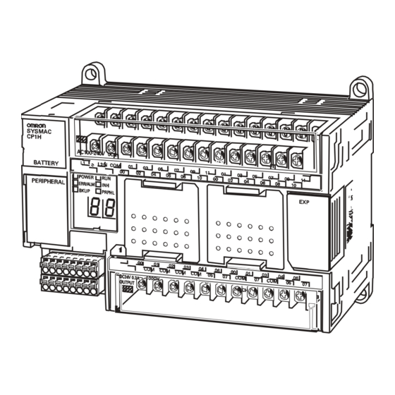
Part Names and Functions Section 2-1 Part Names and Functions 2-1-1 CP1H CPU Units Front Back (12) Option Board slots (11) Power supply, ground, (13) Input indicators 1 (left) and 2 (right) and input terminal block (1) Battery cover (2) Operation indicators (3) Peripheral USB port L2/N POWER... - Page 79 Part Names and Functions Section 2-1 BKUP A user program, parameters, or Data Memory are (Yellow) being written or accessed in the built-in flash mem- ory (backup memory). The BKUP indicator also lights while user programs, parameters, and Data Memory are being restored when the PLC power supply is turned ON.
- Page 80 Part Names and Functions Section 2-1 Setting Description Application Default Used for peripheral Used to enable a Serial bus. Communications Option Board mounted in Option According to PLC Board Slot 2 to be used Setup. by the peripheral bus. A395.12 ON Used to bring about a given condition without A395.12 OFF...
- Page 81 Part Names and Functions Section 2-1 (11) Power Supply, Ground, and Input Terminal Block Power supply ter- Used to provide a 100- to 240-VAC or 24-VDC power minals supply. Ground terminals Functional ground ( Connect this ground to strengthen noise immunity and to prevent electric shock.
-
Page 82: Cp1W-Cif01 Rs-232C Option Boards
Part Names and Functions Section 2-1 (17) Connector for CJ Unit Adapter A maximum total of two CJ-series Special I/O Units or CPU Bus Units can be connected by mounting a CP1W-EXT01 CJ Unit Adapter to the side of a CP1H CPU Unit. CJ-series Basic I/O Units, however, cannot be connected. -
Page 83: Cp1W-Cif11/Cif12 Rs-422A/485 Option Boards
Part Names and Functions Section 2-1 RS-232C Connector Abbr. Signal name Signal direction Frame Ground SD (TXD) Send Data Output RD (RXD) Receive Data Input RS (RTS) Request to Send Output CS (CTS) Clear to Send Input Power Supply DR (DSR) Data Set Retry Input ER (DTR) -
Page 84: Specifications
Specifications Section 2-2 DIP Switch for Operation Settings Settings ON (both ends) Terminating resistance selection Resistance value: 220Ω typical 2-wire 2-wire or 4-wire selection (See note 1.) 4-wire 2-wire 2-wire or 4-wire selection (See note 1.) 4-wire Not used. RS control enabled RS control selection for RD (See note 2.) RS control disabled (Data... - Page 85 Specifications Section 2-2 Power supply AC power supply DC power supply classification Model numbers • XA CPU Units • XA CPU Units • Y CPU Units CP1H-XA40DR-A CP1H-XA40DT-D CP1H-Y20DT-D CP1H-XA40DT1-D • X CPU Units CP1H-X40DR-A • X CPU Units CP1H-X40DT-D CP1H-X40DT1-D Dielectric strength 2,300 VAC 50/60 Hz for 1 min between the...
- Page 86 Specifications Section 2-2 Type X CPU Units XA CPU Units Y CPU Units Model CP1H-X40DR-A CP1H-XA40DR-A CP1H-Y20DT-D CP1H-X40DT-D CP1H-XA40DT-D CP1H-X40DT1-D CP1H-XA40DT1-D Function blocks Maximum number of function block definitions: 128 Maximum number of instances: 256 Languages usable in function block definitions: Ladder diagrams, structured text (ST) Instruction length 1 to 7 steps per instruction...
- Page 87 Specifications Section 2-2 Type X CPU Units XA CPU Units Y CPU Units Model CP1H-X40DR-A CP1H-XA40DR-A CP1H-Y20DT-D CP1H-X40DT-D CP1H-XA40DT-D CP1H-X40DT1-D CP1H-XA40DT1-D Pulse out- Pulse outputs Unit version 1.0 and earlier: 2 outputs, 1 Hz to 100 kHz puts 2 outputs, 1 Hz to 100 kHz Trapezoidal or S-curve acceleration and (Transistor 2 outputs, 1 Hz to 30 kHz...
-
Page 88: I/O Memory Details
Specifications Section 2-2 Type X CPU Units XA CPU Units Y CPU Units Model CP1H-X40DR-A CP1H-XA40DR-A CP1H-Y20DT-D CP1H-X40DT-D CP1H-XA40DT-D CP1H-X40DT1-D CP1H-XA40DT1-D Maximum subroutine number Maximum jump number Scheduled interrupts Clock function Supported. Accuracy (monthly deviation): −4.5 min to −0.5 min (ambient temperature: 55°C), −2.0 min to +2.0 min (ambient temperature: 25°C), −2.5 min to +1.5 min (ambient temperature: 0°C) Memory... -
Page 89: I/O Specifications For Xa And X Cpu Units
Specifications Section 2-2 Type X CPU Units XA CPU Units Y CPU Units Model CP1H-X40DR-A CP1H-XA40DR-A CP1H-Y20DT-D CP1H-X40DT-D CP1H-XA40DT-D CP1H-X40DT1-D CP1H-XA40DT1-D TR Area 16 bits: TR0 to TR15 HR Area 8,192 bits (512 words): H0.00 to H511.15 (words H0 to H511) AR Area Read-only (Write-prohibited) 7,168 bits (448 words): A0.00 to A447.15 (words A0 to A447) - Page 90 Specifications Section 2-2 Setting Input Functions in Functions for the normal input terminals in the built-in inputs can be individu- the PLC Setup ally allocated by making selections in the PLC Setup. Input Input operation High-speed counter Origin search function terminal operation block...
- Page 91 Specifications Section 2-2 Input Specifications Normal Inputs Item Specification CIO 0.04 to CIO 0.11 CIO 0.00 to CIO 0.03 and CIO 1.04 to CIO 1.11 CIO 1.00 to CIO 1.03 Input voltage +10% 24 VDC −15% Applicable inputs 2-wire and 3-wire sensors Input impedance 3.0 kΩ...
- Page 92 Specifications Section 2-2 Simultaneously ON Inputs-Ambient Temperature Characteristic No. of simultaneously ON inputs Input voltage: 24 V DC Input voltage: 26.4 V DC Ambient temperature (°C) High-speed Counter Inputs Differential Pulse plus Up/down input Increment phase mode direction input mode mode mode CIO 0.04,...
- Page 93 Specifications Section 2-2 Interrupt Inputs and Input bits CIO 0.00 to CIO 0.03 and CIO 1.00 to CIO 1.03 can be used not Quick-response Inputs only as normal inputs but also as interrupt or quick-response inputs depend- ing on the settings in the PLC Setup. Input bit Interrupt inputs Quick-response inputs...
- Page 94 Specifications Section 2-2 Output When the When a pulse output instruction When the origin search When the PWM terminal instructions to (SPED, ACC, PLS2, or ORG) is function is set to be used in instruction is block the right are executed the PLC Setup, and an executed...
- Page 95 Specifications Section 2-2 125 VAC resistive load 30 VDC/250 VAC resistive load 30 VDC τ = 7 ms 125 VAC cosφ = 0.4 250 VAC cosφ = 0.4 0.2 0.3 0.5 0.7 1 Contact current (A) Common terminal current (A) Ambient temperature (°C) Transistor Outputs (Sinking or Sourcing) Normal Outputs...
- Page 96 Specifications Section 2-2 Item Specification CIO 100.00 to CIO 100.07 CIO 101.00 and CIO 101.02 to CIO 101.01 CIO 101.07 Fuse 1 fuse/common (See note 1.) Circuit configuration • Normal outputs CIO 100.00 to CIO 100.07 • Normal outputs CIO 101.00, CIO 101.01 and (Sinking Outputs) CIO 101.02 to CIO 101.07 (Sinking Outputs)
-
Page 97: Built-In Analog I/O Specifications (Xa Cpu Units Only)
Specifications Section 2-2 Pulse Outputs (CIO 100.00 to CIO 100.07) Item Specification Max. switching capacity 30 mA/4.75 to 26.4 VDC Min. switching capacity 7 mA/4.75 to 26.4 VDC Max. output frequency 100 kHz Output waveform 4 µs min. 2 µs min. The OFF and ON refer to the output transistor. - Page 98 Specifications Section 2-2 Analog I/O Specifications Model CP1H-XA40DR-A CP1H-XA40DT-D CP1H-XA40DT1-D Item Voltage I/O (See note 1.) Current I/O (See note 1.) Analog Number of 4 inputs (4 words allocated) Input Sec- inputs tion 0 to 5 V, 1 to 5 V, 0 to 10 V, or −10 to 10 V Input signal 0 to 20 mA or 4 to 20 mA range...
-
Page 99: I/O Specifications For Y Cpu Units
Specifications Section 2-2 2-2-5 I/O Specifications for Y CPU Units Relationship between Built-in Inputs and Terminal Block Arrangement Terminal Block Arrangement Upper Terminal Block 24-VDC input terminals − B0+ Z0+ B1+ Z1+ A0− B0− Z0− A1− B1− Z1− Special high-speed counter terminals CIO 0 CIO 1 Normal input terminals... - Page 100 Specifications Section 2-2 Input terminal Input operation setting High-speed counter Origin search block operation setting function Word Terminal/ Normal Interrupt Quick- High-speed counters 0 to 3 Origin search inputs inputs response set to be used. function for pulse (See note.) inputs outputs 0 and 1 set to be used.
- Page 101 Specifications Section 2-2 Normal Inputs Item Specification CIO 0.04, CIO 0.00, CIO 1.04 and CIO 0.05, CIO 0.01, and CIO 1.05 CIO 0.10, and CIO 1.00 to CIO 0.11 CIO 1.03 Input voltage +10% 24 VDC −15% Applicable inputs 2-wire and 3-wire sensors Input impedance 3.0 kΩ...
- Page 102 Specifications Section 2-2 Differential Pulse plus Up/down Increment input mode direction input mode mode input mode Max. count fre- 500 kHz (4×) 1 MHz quency 0.04, 0.10 A-phase pulse Pulse input Increment Increment input pulse input pulse input 0.05, 0.11 B-phase pulse Direction input Decrement...
- Page 103 Specifications Section 2-2 Relationship between Built-in Outputs and Terminal Block Arrangement Terminal Block Arrangement Lower Terminal Block CW0+ CW1+ CCW0+ CCW1+ − CW0− CW1− CCW0− CCW1− Special pulse output terminals 24-VDC input CIO 100 CIO 101 terminals Normal output terminals (See note.) Note 24-VDC input terminals can be used as the power supply terminals for CIO100.04...
- Page 104 Specifications Section 2-2 Output Specifications Special Pulse Outputs Item Specification Special pulse outputs Line-driver output, AM26LS31 or equivalent Max. output current 20 mA Max. output frequency 1 MHz Circuit configuration CWn+ CWn− CCWn+ CCWn− !Caution Connect a load of 20 mA or less to the output load. Connecting a load exceeding 20 mA may cause the Unit to malfunction.
- Page 105 Specifications Section 2-2 (2) If the ambient temperature is maintained below 50°C, up to 0.9 A/com- mon can be used. Common terminal current (A) Ambient temperature (°C) !Caution Do not connect a load to an output terminal or apply a voltage in excess of the maximum switching capacity.
-
Page 106: Cp-Series Expansion I/O Unit I/O Specifications
Specifications Section 2-2 2-2-6 CP-series Expansion I/O Unit I/O Specifications Input Specifications (CP1W-40EDR/40EDT/40EDT1/20EDR1/20EDT/20EDT1/8ED) Item Specification Input voltage +10% 24 VDC −15% Input impedance 4.7 kΩ Input current 5 mA typical ON voltage 14.4 VDC min. OFF voltage 5.0 VDC max. ON delay 0 to 32 ms max. - Page 107 Specifications Section 2-2 Note (1)Under the worst conditions, the service life of output contacts is as shown above. The service life of relays is as shown in the following diagram as a guideline. 120 VAC resistive load 24 VDC τ = 7 ms 120 VAC cosφ...
- Page 108 Specifications Section 2-2 ■ Output Load Current and Ambient Temperature (CP1W-32ER/16ER) With the CP1W-32ER/16ER, the load current is restricted depending on the ambient temperature. Design the system considering the load current based on the following graph. Ambient temperature (°C) Transistor Output (Sinking or Sourcing) Item Specification CP1W-40EDT...
- Page 109 Specifications Section 2-2 (2) If the ambient temperature is maintained below 50°C, up to 0.9 A/com- mon can be used. 50 55 (°C) Ambient temperature !Caution Do not connect a load to an output terminal or apply a voltage in excess of the maximum switching capacity.
-
Page 110: Cp1H Cpu Unit Operation
CP1H CPU Unit Operation Section 2-3 CP1H CPU Unit Operation 2-3-1 Overview of CPU Unit Configuration The CP1H CPU Unit memory consists of the following blocks. 12 or 24 built-in inputs (See note 1.) CPU Unit User program Flash memory Memory Cassette User... - Page 111 CP1H CPU Unit Operation Section 2-3 • CX-Programmer operations can be used to transfer data from RAM to the Memory Cassette or from the built-in flash memory to the Memory Cassette. • When the power supply is turned ON, data is transferred from the Memory Cassette to the built-in flash memory.
- Page 112 CP1H CPU Unit Operation Section 2-3 Routing Tables Tables specifying the communications paths from the Communications Units on the local PLC to remote PLCs connected on other networks must be regis- tered in all the CPU Units in network PLCs to send and receive data between networks.
- Page 113 CP1H CPU Unit Operation Section 2-3 Built-in Flash Memory Flash memory is built into the CP1H CPU Units. Data in the following areas is automatically backed up to the flash memory whenever it is written in any way other than by instructions in the user program, e.g., when the CX-Programmer or PT is used to transfer or edit data, edit the program online, or transfer data from a Memory Cassette.
-
Page 114: Flash Memory Data Transfers
CP1H CPU Unit Operation Section 2-3 2-3-2 Flash Memory Data Transfers Built-in Flash Memory Writing to Flash Memory Data Transfer method User program and This data is automatically transferred from RAM to flash mem- parameter data ory when a project is transferred from the CX-Programmer, when the data is written to RAM from a PT or other external device, or when the data is transferred from a Memory Cas- sette. - Page 115 CP1H CPU Unit Operation Section 2-3 Reading from Flash Memory Data Read method User program and This data is automatically read to RAM when power is turned parameter data DM Area data Reading this data when power is turned ON can be enabled or disabled in the PLC Setup.
-
Page 116: Memory Cassette Data Transfers
CP1H CPU Unit Operation Section 2-3 2-3-3 Memory Cassette Data Transfers Writing to a Memory Cassette Data Method Source User program and Data is written to a Memory Data in the built-in flash mem- parameter data Cassette using write opera- ory is written to the Memory tions from the CX-Program- Cassette. - Page 117 CP1H CPU Unit Operation Section 2-3 Reading from a Memory Cassette Data Method Destination User program and This data is transferred by Data in the Memory Cassette parameter data turning SW2 on the DIP is transferred to RAM and switch to ON and turning ON then automatically transferred the power supply.
-
Page 118: Cpu Unit Operation
CPU Unit Operation Section 2-4 CPU Unit Operation 2-4-1 General Flow The following flowchart shows the overall operation of the CPU Unit. First the user program is executed and then I/O is refreshed and peripheral servicing is performed. These processes are then repeated in cyclic fashion. Power ON Startup Initialize hardware... -
Page 119: I/O Refreshing And Peripheral Servicing
CPU Unit Operation Section 2-4 2-4-2 I/O Refreshing and Peripheral Servicing I/O Refreshing I/O refreshing involves cyclically transferring data with external devices using preset words in memory. I/O refreshing includes the following: • Refreshing between CPU Unit built-in I/O, CP-series Expansion Units, and CP-series Expansion I/O Units and I/O words in the CIO Area •... -
Page 120: I/O Refresh Methods
CPU Unit Operation Section 2-4 Service Description Communications port servic- • Servicing to execute network communications or serial communications for the SEND, RECV, CMND or PMCR instructions using communications ports 0 to 7 (internal logical ports) • Servicing to execute background execution using communications ports 0 to 7 (internal logical ports) Built-in flash memory access •... - Page 121 CPU Unit Operation Section 2-4 Immediate Refreshing When the immediate refreshing variation of an instruction is specified and the instruction’s operand is an input bit or word in the Built-in I/O Area, the word containing the bit or the word itself will be refreshed. Immediate refresh 0.00 CIO 0...
-
Page 122: Initialization At Startup
CPU Unit Operation Section 2-4 2-4-4 Initialization at Startup The following initializing processes will be performed once each time the power is turned ON. • Confirm mounted Units and I/O allocations. • Clear the non-holding areas of I/O memory according to the status of the IOM Hold Bit. -
Page 123: Cpu Unit Operating Modes
CPU Unit Operating Modes Section 2-5 CPU Unit Operating Modes 2-5-1 Operating Modes The CPU Unit has three operating modes that control the entire user program and are common to all tasks. PROGRAM: Programs are not executed and preparations, such as initial- izing the PLC Setup and other settings, transferring pro- grams, checking programs, force-setting and force-resetting can be executed prior to program execution. -
Page 124: Operating Mode Changes And I/O Memory
CPU Unit Operating Modes Section 2-5 2-5-3 Operating Mode Changes and I/O Memory Operating Mode Changes and I/O Memory Mode Changes Non-holding areas Holding Areas • I/O bits • HR Area • Data Link bits • DM Area • CPU Bus Unit bits •... -
Page 125: Power Off Operation
Power OFF Operation Section 2-6 Note A Programming Console cannot be connected to a CP1H CPU Unit. If Use programming console is set, the CPU Unit will start in RUN mode. Power OFF Operation 2-6-1 Overview The following processing is performed when CPU Unit power is turned OFF. Power OFF processing will be performed if the power supply voltage falls below the specified value while the CPU Unit is in RUN or MONITOR mode. -
Page 126: Instruction Execution For Power Interruptions
Power OFF Operation Section 2-6 2. A momentary power interruption that lasts more than 10 ms for AC power or more than 2 ms for DC power may or may not be detected. 85% of the rated voltage or less for AC power 90% of the rated voltage or less or DC power 10 ms Time... -
Page 127: Computing The Cycle Time
Computing the Cycle Time Section 2-7 Computing the Cycle Time 2-7-1 CPU Unit Operation Flowchart The CPU Unit processes data in repeating cycles from the overseeing pro- cessing up to peripheral servicing as shown in the following diagram. Power ON Checks Unit connection status. -
Page 128: Cycle Time Overview
Computing the Cycle Time Section 2-7 2-7-2 Cycle Time Overview The cycle time depends on the following conditions. • Type and number of instructions in the user program (in all cyclic tasks that are executed during a cycle, and within interrupt tasks for which the execution conditions have been satisfied) •... - Page 129 Computing the Cycle Time Section 2-7 4: I/O Refreshing Details Processing time and fluctuation cause CPU Unit built- Outputs from the CPU Unit to the actual I/O refresh time for each Unit multiplied by the number of in I/O and I/O outputs are refreshed first for each Unit, Units used.
-
Page 130: Functions Related To The Cycle Time
Computing the Cycle Time Section 2-7 2-7-3 Functions Related to the Cycle Time Minimum Cycle Time Set the minimum cycle time to a non-zero value to eliminate inconsistencies in I/O responses. A minimum cycle time can be set in the PLC Setup between 1 and 32,000 ms in 1-ms increments. -
Page 131: I/O Refresh Times For Plc Units
Computing the Cycle Time Section 2-7 Related Words Name Addresses Description Maximum Cycle A262 and These words contain the maximum cycle time in Time A263 increments of 0.1 ms. The time is updated every cycle and is recorded in 32-bit binary (0 to FFFF FFFF hex, or 0 to 429,496,729.5 ms). - Page 132 Computing the Cycle Time Section 2-7 Name Model I/O refresh time per Unit Temperature Sensor Units CP1W-TS001 0.25 ms CP1W-TS002 0.52 ms CP1W-TS003 0.67 ms CP1W-TS004 0.47 ms CP1W-TS101 0.25 ms CP1W-TS102 0.52 ms CompoBus/S I/O Link Unit CP1W-SRT21 0.21 ms Note The I/O refresh time for CPU Unit built-in I/O is included in overhead processing.
-
Page 133: Cycle Time Calculation Example
Computing the Cycle Time Section 2-7 2-7-5 Cycle Time Calculation Example The following example shows the method used to calculate the cycle time when CP-series Expansion I/O Units only are connected to a CP1H CPU Unit. Conditions Item Details CP1H CP1W-40EDR 2 Units 40-pt I/O Unit... -
Page 134: I/O Response Time
Computing the Cycle Time Section 2-7 When editing online, the cycle time will be extended by according to the edit- ing that is performed. Be sure that the additional time will not adversely affect system operation. Note When there is one task, online editing is processed all in the cycle time follow- ing the cycle in which online editing is executed (written). -
Page 135: Interrupt Response Times
Computing the Cycle Time Section 2-7 I/O refresh Input Input ON delay (Interrupt to CPU Unit) Cycle time Cycle time Instruction Instruction Instruction execution execution execution Output ON delay Output Maximum I/O response time Calculation Example Conditions: Input ON delay 1 ms Output ON delay 0.1 ms... - Page 136 Computing the Cycle Time Section 2-7 been executed. The length of the interrupt response time for I/O interrupt tasks depends on the following conditions. About 0.3 ms Item Interrupt response time Counter interrupts Rise time: 50 µs Hardware response Fall time: 50 µs Minimum: 98 µs Minimum: 187 µs Software interrupt...
-
Page 137: Serial Plc Link Response Performance
Computing the Cycle Time Section 2-7 Scheduled interrupt time Internal timer Software interrupt response time Scheduled interrupt task (2) When using input interrupt or pulse output 2/3 and analog input/output (XA type only), pay attention to the possibility that timer interrupt cannot be executed within short time interval. -
Page 138: Pulse Output Change Response Time
Computing the Cycle Time Section 2-7 Pulse output instruction Start time 53 µs SPED: continuous 55 µs SPED: independent 65 µs ACC: continuous 69 µs ACC: independent, trapezoidal 70 µs ACC: independent, triangular 74 µs PLS2: trapezoidal 76 µs PLS2: triangular 2-7-11 Pulse Output Change Response Time The pulse output change response time is the time for any change made by executing an instruction during pulse output to actually affect the pulse output... -
Page 139: Installation And Wiring
SECTION 3 Installation and Wiring This section describes how to install and wire the CP1H. Fail-safe Circuits ..........Installation Precautions . -
Page 140: Fail-Safe Circuits
Fail-safe Circuits Section 3-1 Fail-safe Circuits Always set up safety circuits outside of the PLC to prevent dangerous condi- tions in the event of errors in the PLC or external power supply. In particular, be careful of the following points. Supply Power to the If the PLC's power supply is turned ON after the controlled system's power PLC before the... -
Page 141: Installation Precautions
Installation Precautions Section 3-2 Installation Precautions 3-2-1 Installation and Wiring Precautions Always consider the following factors when installing and wiring the PLC to improve the reliability of the system and make the most of the CP1H func- tions. Ambient Conditions Do not install the PLC in any of the following locations. - Page 142 Installation Precautions Section 3-2 Accessibility for • To ensure safe access for operation and maintenance, separate the PLC Operation and as much as possible from high-voltage equipment and moving machinery. Maintenance • The PLC will be easiest to install and operate if it is mounted at a height of about 1,000 to 1,600 mm.
-
Page 143: Mounting
Mounting Section 3-3 • Do not install the CP1H in any of the following orientations. Mounting 3-3-1 Mounting in a Panel When mounting the CP1H CPU Unit in a panel, use either surface installation or DIN Track installation. Surface Installation Even if a DIN Track is not used, a CP1H CPU Unit and CP-series Expansion Units or Expansion I/O Units can be mounted using M4 screws. - Page 144 Mounting Section 3-3 DIN Track Installation CJ-series Special I/O Units or CPU Bus Units must be mounted to a DIN Track, along with the CP1H CPU Unit. Secure the DIN Track with screws in at least three places. CJ1W-TER01 CP1W-EXT01 CJ-series End Cover CJ Unit Adapter (included with CJ Unit Adapter)
- Page 145 Mounting Section 3-3 Use I/O Connecting Cable when connecting CP-seriess Expansion Units and Expansion I/O Units at the same time as CJ-series Special I/O Units or CPU Bus Units. CP1H CPU Unit DIN Track CP1W-CN811 I/O Connecting Cable Wiring Ducts Whenever possible, route I/O wiring through wiring ducts.
- Page 146 Mounting Section 3-3 Routing Wiring Ducts Install the wiring ducts at least 20 mm between the tops of the Racks and any other objects, (e.g., ceiling, wiring ducts, structural supports, devices, etc.) to provide enough space for air circulation and replacement of Units. Input duct Output duct Power duct...
-
Page 147: Connecting Cp-Series Expansion Units And Expansion I/O Units
Mounting Section 3-3 Mounting Dimensions 140±0.5 100±0.2 Four, M4 For the dimensions of Units other than CP1H CPU Units, refer to Appendix B Dimensions Diagrams. Mounting Height The mounting height is approximately 90 mm. When a cable is connected to an Option Board, however, the additional height must be factored in. - Page 148 Mounting Section 3-3 Unit A (mm) 140 ±0.5 CP1H CPU Unit 140 ±0.2 Expansion I/O Unit, 32 or 40 I/O points 76 ±0.2 Expansion I/O Unit, 20 I/O points 76 ±0.2 Expansion I/O Unit, 16 outputs 56 ±0.2 Expansion I/O Unit, 8 inputs 56 ±0.2 Expansion I/O Unit, 8 outputs 76 ±0.2...
-
Page 149: Connecting Cj-Series Units
Mounting Section 3-3 3. Replace the cover on the CPU Unit's or the Expansion I/O Unit's expansion connector. SYSM AC CP1H AC10 0-240 V BAT TER Y L2/N COM POWE R PER IPHE RAL ERR/A LM BKUP PRPH L 40 ED R DC24 V 0.3A 100C H OUTP UT... -
Page 150: Din Track Installation
Mounting Section 3-3 • Slide the yellow sliders at the top and bottom of each Unit to lock the Units together. Move the sliders toward the back until they lock into place. Lock Release Slider Note If the sliders are not secured properly, the Unit may not function properly. 3. - Page 151 Mounting Section 3-3 2. Lower the Units so that they catch on the top of the DIN Track, and then press them forward all the way to the DIN Track at the bottom. 3. Press in all of the DIN Track mounting pins to securely lock the Units in place.
-
Page 152: Wiring Cp1H Cpu Units
Wiring CP1H CPU Units Section 3-4 DIN Track Mount the DIN Track in the control panel with screws in at least three places. • DIN Track: PFP-50N (50 cm), PFP-100N (100 cm), or PFP-100N2 (100 cm) Secure the DIN Track to the control panel using M4 screws separated by 210 mm (6 holes). -
Page 153: Wiring Power Supply And Ground Lines
Wiring CP1H CPU Units Section 3-4 3-4-1 Wiring Power Supply and Ground Lines CPU Units with AC Power Supply Wiring the AC Power Supply and Ground Lines 100 to 240 VAC at 50/60 Hz MCCB Upper terminal block L2/N COM LG: Functional ground terminal GR: Protective ground terminal Ground (100 Ω... - Page 154 Wiring CP1H CPU Units Section 3-4 • The GR terminal is a ground terminal. To prevent electrical shock, use a min.) of 100 Ω or less. dedicated ground line (2 mm • The line ground terminal (LG) is a noise-filtered neutral terminal. If noise is a significant source of errors or if electrical shocks are a problem, con- nect the line ground terminal (LG) to the ground terminal (GR) and ground both with a ground resistance of 100 Ω...
-
Page 155: Wiring Built-In I/O
Wiring CP1H CPU Units Section 3-4 3-4-2 Wiring Built-in I/O Wiring Precautions Double-checking I/O Double-check the specifications for the I/O Units. In particular, do not apply a Specifications voltage that exceeds the input voltage for Input Units or the maximum switch- ing capacity for Output Units. - Page 156 Wiring CP1H CPU Units Section 3-4 Connecting I/O Use the following information for reference when selecting or connecting input Devices devices. DC Input Devices Connectable DC Input Devices (for DC Output Models) Contact output CP1H Two-wire DC output CP1H Sensor power supply NPN open-collector output Sensor...
- Page 157 Wiring CP1H CPU Units Section 3-4 • The circuit below should not be used for I/O devices with a voltage output. Sensor power supply Output CP1H − Precautions when When using a two-wire sensor with a 24-V DC input device, check that the fol- Connecting a Two-wire DC lowing conditions have been met.
- Page 158 In this example, the sensor's power supply voltage is provided to input bit CIO 0.00 and a 100-ms timer delay (the time required for an OMRON Proximity Sensor to stabilize) is created in the program. After the Completion Flag for the timer turns ON, the sensor input on input bit CIO 0.01 will cause output bit...
-
Page 159: Wiring Safety And Noise Controls
Wiring CP1H CPU Units Section 3-4 3-4-3 Wiring Safety and Noise Controls I/O Signal Wiring Whenever possible, place I/O signal lines and power lines in separate ducts or conduits both inside and outside of the control panel. (1) = I/O cables (2) = Power cables In-floor duct Conduits... -
Page 160: Wiring Methods
Wiring Methods Section 3-5 Low-current cables PLC I/O wiring 300 mm min. Control cables PLC power supply cable and general control circuit wiring 300 mm min. Power cables Power lines Ground to 100 Ω or less • If the I/O wiring and power cables must be placed in the same duct, they must be shielded from each other using grounded steel sheet metal. - Page 161 Wiring Methods Section 3-5 Output Wiring (Terminal Block is Removable) CP1H-XA40DR-A and Lower Terminal Block CP1H-X40DR-A (Relay CIO 101 Output) CIO 100 − COM COM COM COM CIO 100 CIO 101 CP1H-XA40DT-D and Lower Terminal Block CP1H-X40DT-D (Sinking CIO 100 CIO 101 Transistor Output) NC 00...
-
Page 162: Example I/O Wiring For Y Cpu Units
Wiring Methods Section 3-5 3-5-2 Example I/O Wiring for Y CPU Units Input Wiring (Terminal The input circuits for Y CPU Units have 24 points/common. Use power lines Block is Removable) with sufficient current capacity for the COM terminals. Encoder Power supply CIO 0 CIO 1... -
Page 163: Pulse Input Connection Examples
Wiring Methods Section 3-5 3-5-3 Pulse Input Connection Examples For a 24-VDC Open- This example shows the connections to an encoder with phase-A, phase-B, collector Encoder and phase Z inputs. CP1H CPU Unit (X or Y CPU Unit) (Differential phase input mode) Phase A Black (High-speed counter 0:... -
Page 164: Pulse Output Connection Examples
Wiring Methods Section 3-5 Power provided. Encoder CP1H CPU Unit Shielded twisted-pair cable A0− A− B0− B− Z− Z0− 3-5-4 Pulse Output Connection Examples This example shows a connection to a motor driver. Always check the specifi- cations of the motor driver before actually connecting it. For open-collector output, use a maximum of 3 m of wiring between the CP1H CPU Unit and the motor driver. - Page 165 Wiring Methods Section 3-5 CW/CCW Pulse Output and Pulse Plus Direction Output Using a 24-VDC Photocoupler Input Motor Driver 24-V DC power supply CPIH CPU Unit Motor driver (for 24-V input) − 24-VDC power supply for outputs (−) CW pulse output (Pulse output)
-
Page 166: Wiring Built-In Analog I/O (Xa Cpu Units Only)
Wiring Methods Section 3-5 Connection Example 2 5-V DC power supply CPIH CPU Unit Motor driver (for 5-V input) − (−) 100.02 CW pulse output (Pulse output) (−) 100.03 CCW pulse output (Direction output) Note The values inside the parentheses are for using pulse and direction outputs. 3-5-5 Wiring Built-in Analog I/O (XA CPU Units Only) XA CPU Units come with an analog I/O terminal block. - Page 167 Wiring Methods Section 3-5 Analog Input Terminal Block (Terminal Block is Removable) 3 4 5 6 7 8 Function IN1+ IN1− IN2+ IN2− IN3+ IN3− IN4+ IN4− Analog Output Terminal Block (Terminal Block is Removable) 9 10 11 12 13 14 15 16 Function OUT V1+ OUT I1+...
- Page 168 Wiring Methods Section 3-5 circuiting the plus and minus terminals. If the range is set for 1 to 5 V and 4 to 20 mA, however, the Open-circuit Detection Flag will turn ON when the plus and minus terminals are short-circuited. Terminal Block Wiring When wiring the analog I/O terminal block, either use ferrules or solid wires.
-
Page 169: Cp-Series Expansion I/O Unit Wiring
CP-series Expansion I/O Unit Wiring Section 3-6 I/O Wiring Precautions To enable using the analog I/O under optimal conditions, be careful of the fol- lowing points for noise reduction. • Use 2-conductor shielded twisted-pair cable for the I/O wiring, and do not connect the shield. - Page 170 CP-series Expansion I/O Unit Wiring Section 3-6 40-point I/O Units (CP1W-40ED ) (Terminal Block is not Removable) Input Wiring CIO m+1 CIO m+2 24 VDC − − NC COM 01 CIO m+1 CIO m+2 Output Wiring CP1W-40EDR (Relay Output) NC COM COM COM 03 COM 06 COM COM 06 250 VAC...
- Page 171 CP-series Expansion I/O Unit Wiring Section 3-6 CP1W-40EDT1 (Sourcing Transistor Output) NC COM COM COM 03 COM 06 COM COM 06 4.5 to 30 VDC 32-point Output Units (CP1W-32E ) (Terminal Block is not Removable) Output Wiring CP1W-32ER (Relay Outputs) Upper Terminal Block Lower Terminal Block CIO n+1...
- Page 172 CP-series Expansion I/O Unit Wiring Section 3-6 Output Wiring CP1W-32ET1 (Sourcing Transistor Outputs) Upper Terminal Block Lower Terminal Block CIO n+1 CIO n+2 CIO n+3 CIO n+4 COM COM COM COM NC NC NC 06 NC COM COM COM COM CIO n+1 CIO n+2 CIO n+3...
- Page 173 CP-series Expansion I/O Unit Wiring Section 3-6 CP1W-20EDT (Sinking Transistor Output) COM COM COM 03 COM 06 CP1W-20EDT1 (Sourcing Transistor Output) COM COM COM 03 COM 06 16-point Output Units (CP1W-16E ) (Terminal Block is not Removable) Output Wiring CP1W-16ER (Relay Outputs) Unit Lower Terminal Block Unit Upper Terminal Block NC COM...
- Page 174 CP-series Expansion I/O Unit Wiring Section 3-6 Output Wiring CP1W-16ET (Sinking Transistor Outputs) Upper Terminal Block Lower Terminal Block CIO n+1 CIO n+2 NC COM COM COM NC COM CIO n+2 CIO n+1 CP1W-16ET1 (Sourcing Transistor Outputs) Upper Terminal Block Lower Terminal Block CIO n+2 CIO n+1...
- Page 175 CP-series Expansion I/O Unit Wiring Section 3-6 8-point Output Units (CP1W-8E ) (Terminal Block is not Removable) Output Wiring CP1W-8ER (Relay Output) Unit Upper Terminal Block Unit Lower Terminal Block CP1W-8ET (Sinking Transistor Output) Unit Upper Terminal Block Unit Lower Terminal Block 4.5 to 30 VDC −...
- Page 176 CP-series Expansion I/O Unit Wiring Section 3-6...
-
Page 177: I/O Memory Allocation
SECTION 4 I/O Memory Allocation This section describes the structure and functions of the I/O Memory Areas and Parameter Areas. Overview of I/O Memory Area........4-1-1 I/O Memory Area . -
Page 178: Overview Of I/O Memory Area
Overview of I/O Memory Area Section 4-1 Overview of I/O Memory Area 4-1-1 I/O Memory Area This region of memory contains the data areas that can be accessed as instruction operands. I/O memory includes the CIO Area, Work Area, Holding Area, Auxiliary Area, DM Area, Timer Area, Counter Area, Task Flag Area, Data Registers, Index Registers, Condition Flag Area, and Clock Pulse Area. - Page 179 Overview of I/O Memory Area Section 4-1 Area Size Range Task usage Allocation Word Access Change Forcing access access from CX- Read Write Programmer status TR Area 16 bits TR0 to Shared by TR15 all tasks Data Memory Area 32,768 D00000 words (Note...
-
Page 180: Overview Of The Data Areas
Overview of I/O Memory Area Section 4-1 4-1-2 Overview of the Data Areas ■ CIO Area It is not necessary to input the “CIO” acronym when specifying an address in the CIO Area. The CIO Area is generally used for data exchanges, such as I/O refreshing with PLC Units. - Page 181 Overview of I/O Memory Area Section 4-1 CPU Bus Unit Area These words are used when connecting the CJ-series CPU Bus Units. Words that aren’t used by CPU Bus Units may be used in programming. Special I/O Unit Area These words are used when connecting the CJ-series Special I/O Units. Words that aren’t used by Special I/O Units may be used in programming.
- Page 182 Overview of I/O Memory Area Section 4-1 Auxiliary Area (A) These words are allocated to specific functions in the system. Refer to Appendix C Auxiliary Area Allocations by Function and Appendix D Auxiliary Area Allocations by Address for details on the Auxiliary Area. Word Read-only area A447...
- Page 183 Overview of I/O Memory Area Section 4-1 Counter Area (C) There are two parts to the Counter Area: the Counter Completion Flags and the Counter Present Values (PVs). Up to 4,096 counters with counter num- bers C0 to C4095 can be used. Counter Completion Flags These flags are read as individual bits.
-
Page 184: Clearing And Holding I/O Memory
Overview of I/O Memory Area Section 4-1 4-1-3 Clearing and Holding I/O Memory Area Fatal error generated Mode changed PLC power turned ON Execution of FALS Other fatal errors PLC Setup set to PLC Setup set to clear IOM Hold Bit hold IOM Hold Bit status status... - Page 185 Overview of I/O Memory Area Section 4-1 Note *The following areas of I/O memory will be cleared during mode changes (between PROGRAM and RUN/MONITOR) unless the IOM Hold Bit is ON: the CIO Area (I/O Area, Data Link Area, CPU Bus Unit Area, Special I/O Unit Area, DeviceNet (CompoBus/D) Area, and Internal I/O Areas), Work Area, Timer Completion Flags, and Timer PVs.
-
Page 186: I/O Area And I/O Allocations
I/O Area and I/O Allocations Section 4-2 I/O Area and I/O Allocations Input Bits: CIO 0.00 to CIO 16.15 (17 words) Output Bits: CIO 100.00 to CIO 116.15 (17 words) The starting words for inputs and outputs are predetermined for CP1H CPU Unit. -
Page 187: Allocations To Built-In General Purpose I/O On The Cpu Unit
I/O Area and I/O Allocations Section 4-2 4-2-2 Allocations to Built-in General Purpose I/O on the CPU Unit The bits that are allocated depend on the model of CPU Unit, as shown in the following figures. Allocations for X and XA CPU Units (24 Inputs/16 Outputs) Bits are allocated for X and XA CPU Units as shown in the following figure. -
Page 188: Allocations To Cp1H Y Cpu Units (12 Inputs/8 Outputs)
I/O Area and I/O Allocations Section 4-2 4-2-3 Allocations to CP1H Y CPU Units (12 Inputs/8 Outputs) Bits are allocated to a Y CPU Unit in discontinuous positions, as shown in the figure below, due to allocations for the pulse I/O terminals. CPU Unit Expansion Unit CIO 2.00 on... - Page 189 I/O Area and I/O Allocations Section 4-2 I/O Unit, or CPU Unit are automatically allocated. This word is indicated as “CIO m” for input words and as “CIO n” for output words. Unit Input bits Output bits No. of No. of Addresses No.
- Page 190 I/O Area and I/O Allocations Section 4-2 Units with 16 Output Points (CP1W-16E Sixteen output bits in two words are allocated in two words (bits 00 to 07 in CIO n and bits 00 to 07 in CIO n+1). Output Can be used as work bits.
- Page 191 I/O Area and I/O Allocations Section 4-2 Unit Input words Output words Analog Output Units CP1W-DA021 None 2 words CIO n to CIO n+1 CP1W-DA041 None 4 words CIO n to CIO n+3 CP1W-DA042 Temperature Sensor Units CP1W-TS001 2 words CIO m to CIO m+1 None CP1W-TS002 4 words CIO m to CIO m+3 None CP1W-TS003...
-
Page 192: I/O Allocation Examples
I/O Area and I/O Allocations Section 4-2 4-2-5 I/O Allocation Examples Do not exceed the connection restrictions when connecting Expansion Units and Expansion I/O Units. 1. A maximum of up to 7 Units can be connected. 2. A maximum of 15 input and output words can be allocated (Input: up to CIO 16, output: up to CIO 116). -
Page 193: Built-In Analog I/O Area (Xa Cpu Units Only)
Built-in Analog I/O Area (XA CPU Units Only) Section 4-3 Built-in Analog I/O Area (XA CPU Units Only) Built-in Analog Input Bits: CIO 200 to CIO 203 (4 words) Built-in Analog Output Bits: CIO 210 to CIO 211 (2 words) The built-in analog inputs and built-in analog outputs for XA CPU Units are always allocated words between CIO 200 and CIO 211. -
Page 194: Data Link Area
Data Link Area Section 4-4 Data Link Area Data Link Area addresses range from CIO 1000 CIO 1199 (bits CIO 1000.00 to CIO 1199.15). Words in the Link Area are used for data links when LR is set as the data link area for Controller Link Networks. It is also used for PLC Links. -
Page 195: Cpu Bus Unit Area
CPU Bus Unit Area Section 4-5 CPU Bus Unit Area The CPU Bus Unit Area contains 400 words with addresses ranging from CIO 1500 to CIO 1899. Words in the CPU Bus Unit Area can be allocated to CPU Bus Units to transfer data such as the operating status of the Unit. Each Unit is allocated 25 words based on the Unit’s unit number setting. -
Page 196: Special I/O Unit Area
Special I/O Unit Area Section 4-6 Special I/O Unit Area The Special I/O Unit Area contains 960 words with addresses ranging from CIO 2000 to CIO 2959. Words in the Special I/O Unit Area are allocated to transfer data, such as the operating status of the Unit. Each Unit is allocated 10 words based on its unit number setting. -
Page 197: Serial Plc Link Area
Serial PLC Link Area Section 4-7 Serial PLC Link Area The Serial PLC Link Area contains 90 words with addresses ranging from CIO 3100 to CIO 3189 (bits CIO 3100.00 to CIO 3189.15). Words in the Serial PLC Link Area can be used for data links with other PLCs. Serial PLC Links exchange data among CPU Units via the built-in RS-232C ports, with no need for special programming. - Page 198 DeviceNet Area Section 4-8 The following words are allocated to the DeviceNet Unit when the remote I/O slave function is used with fixed allocations. Area Output Area Input Area (master to slaves) (slaves to master) Fixed Allocation Area 1 CIO 3370 CIO 3270 Fixed Allocation Area 2 CIO 3570...
-
Page 199: Internal I/O Area
Internal I/O Area Section 4-9 Internal I/O Area The Internal I/O (Work) Area contains 512 words with addresses ranging from W0 to W511. These words can be used in programming as work words. There are unused words in the CIO Area (CIO 1200 to CIO 1499 and CIO 3800 to CIO 6143) that can also be used in the program, but use any available words in the Work Area first because the unused words in the CIO Area may be allocated to other applications when functions are expanded. -
Page 200: Auxiliary Area (A)
Auxiliary Area (A) Section 4-11 area). These words cannot be specified as instruction operands in the user program. Precautions When a Holding Area bit is used in a KEEP(011) instruction, never use a nor- mally closed condition for the reset input if the input device uses an AC power supply. -
Page 201: Timers And Counters
Timers and Counters Section 4-13 Examples In this example, a TR bit is used when two outputs have been directly con- nected to a branch point. Instruction Operand 0.00 0.02 0.03 0.00 0.01 TR 0 0.01 0.04 0.05 0.02 0.03 TR 0 0.04 0.05... - Page 202 Timers and Counters Section 4-13 The refresh method for timer PVs can be set from the CX-Programmer to either BCD or binary. Note It is not recommended to use the same timer number in two timer instructions because the timers will not operate correctly if they are timing simultaneously. (If two or more timer instructions use the same timer number, an error will be generated during the program check, but the timers will operate as long as the instructions are not executed in the same cycle.)
-
Page 203: Counter Area (C)
Timers and Counters Section 4-13 4-13-2 Counter Area (C) The 4,096 counter numbers (C0000 to C4095) are shared by the CNT, CNTX(546), CNTR(012), CNTRX(548), CNTW(814), and CNTWX(818) instructions. Counter Completion Flags and present values (PVs) for these instructions are accessed with the counter numbers. When a counter number is used in an operand that requires bit data, the counter number accesses the Completion Flag of the counter. -
Page 204: Data Memory Area (D)
Data Memory Area (D) Section 4-14 4-13-3 Changing the BCD or Binary Mode for Counters and Timers The refresh method for set values and present values for timers and counters can be changed from BCD mode (0000 to 9999) to binary method (0000 to FFFF) using the CX-Programmer This setting is made in common for all tasks for all timers and counters. - Page 205 Data Memory Area (D) Section 4-14 Forcing Bit Status Bits in the DM Area cannot be force-set or force-reset. Indirect Addressing Words in the DM Area can be indirectly addressed in two ways: binary-mode and BCD-mode. Binary-mode Addressing (@D) When a “@” character is input before a DM address, the content of that DM word is treated as binary and the instruction will operate on the DM word at that binary address.
-
Page 206: Index Registers
Index Registers Section 4-15 CPU Bus Units (D30000 to D31599) Each CPU Bus Unit is allocated 100 words (based on unit numbers 0 to F). Refer to the Unit’s operation manual for details on the function of these words. With some CPU Bus Units such as Ethernet Units, initial settings must be reg- istered in the CPU Unit’s Parameter Area;... - Page 207 Index Registers Section 4-15 With the offset and increment/decrement variations, the Index Registers can be set to base values with MOVR(560) or MOVRW(561) and then modified as pointers in each instruction. I/O Memory Pointer Set to a base value with MOVR(560) or MOVRW(561).
- Page 208 Index Registers Section 4-15 PLC memory Regular address data area MOVE TO REGISTER instruction address I/O memory MOVR(560) 0002 IR0 Pointer #0001 #0020 Note The PLC memory addresses are listed in the diagram above, but it isn’t nec- essary to know the PLC memory addresses when using Index Registers. Since some operands are treated as word data and others are treated as bit data, the meaning of the data in an Index Register will differ depending on the operand in which it is used.
-
Page 209: Using Index Registers
Index Registers Section 4-15 tions shown in the following table. Use these instructions to operate on the Index Registers as pointers. The Index Registers cannot be directly addressed in any other instructions, although they can usually be used for indirect addressing. Instruction group Instruction name Mnemonic... - Page 210 Index Registers Section 4-15 4. Steps 2 and 3 are processed repeatedly until the conditions are met. Note Adding, subtracting incrementing, or decrementing for the Index Register is performed using one of the following methods. • Each Type of Indirect Addressing for Index Registers: Auto-increment (,IR + or ,IR ++), auto-decrement (,-IR or ,--IR ), constant offset (constant ,IR ), and DR offset (DR ,IR ) for Index...
-
Page 211: Precautions For Using Index Registers
Index Registers Section 4-15 W0.00 MOVRW The PLC memory address for the PV area for TO is set in IR0. 0000 D100 W0.00 MOVR The PLC memory address for the T0000 Completion Flag for TO is set in IR1. W0.01 MOVR The PLC memory address for W0.00 0001... - Page 212 Index Registers Section 4-15 Limitations when Using Index Registers • It is only possible to read the Index Register for the last task executed within the cycle from the CX-Programmer. If using Index Registers with the same number to perform multiple tasks, it is only possible with the CX- Programmer to read the Index Register value for the last task performed within the cycle from the multiple tasks, nor is it possible to write the Index Register value from the CX-Programmer.
-
Page 213: Data Registers
Data Registers Section 4-16 Note Be sure to use PLC memory addresses in Index Registers. IR storage words for task 1 Task 1 D1001 and D1000 stored in IR0 Actual memory address of CIO 0 (0000C000 hex) stored in IR0 Contents of IR0 stored in D01001 and D01000 IR storage words for task 2... - Page 214 Data Registers Section 4-16 Normal instructions can be used to store data in Data Registers. Forcing Bit Status Bits in Data Registers cannot be force-set and force-reset. I/O Memory Set to a base value with MOVR(560) or Pointer MOVRW(561). Set with a regular instruction.
-
Page 215: Task Flags
Task Flags Section 4-17 4-17 Task Flags Task Flags range from TK00 to TK31 and correspond to cyclic tasks 0 to 31. A Task Flag will be ON when the corresponding cyclic task is in executable (RUN) status and OFF when the cyclic task hasn’t been executed (INI) or is in standby (WAIT) status. - Page 216 Condition Flags Section 4-18 Name Symbol Function Carry Flag P_CY Turned ON when there is a carry in the result of an arithmetic opera- tion or a “1” is shifted to the Carry Flag by a Data Shift instruction. The Carry Flag is part of the result of some Data Shift and Symbol Math instructions.
-
Page 217: Clock Pulses
Clock Pulses Section 4-19 Saving and Loading Condition Flag Status The CP1-H CPU Units support instructions to save and load the Condition Flag status (CCS(282) and CCL(283)). These can be used to access the sta- tus of the Condition Flags at other locations in a task or in a different task. The following example shows how the Equals Flag is used at a different loca- tion in the same task. - Page 218 Clock Pulses Section 4-19 The Clock Pulses are read-only; they cannot be overwritten from instructions or the CX-Programmer. The Clock Pulses are cleared at the start of operation. Using the Clock Pulses The following example turns CIO 100.00 ON and OFF at 0.5 s intervals. 100.00 Instruction Operand...
-
Page 219: Basic Cp1H Functions
SECTION 5 Basic CP1H Functions This section describes the CP1H’s interrupt and high-speed counter functions. Interrupt Functions ..........5-1-1 Overview of CP1H Interrupt Functions . -
Page 220: Interrupt Functions
Interrupt Functions Section 5-1 Interrupt Functions 5-1-1 Overview of CP1H Interrupt Functions The CP1H CPU Unit’s processing is normally cyclical (overseeing processing → → → program execution I/O refreshing peripheral servicing), with cyclic tasks executed in the program execution stage of the cycle. The interrupt functions can be used to temporarily interrupt this cyclic processing and exe- cute a particular program when a predefined condition occurs. - Page 221 Interrupt Functions Section 5-1 Creating an Interrupt Task Program 1,2,3... 1. Select NewPLC1 [CP1H] Offline in the project workspace, right-click, and select Insert Program in the pop-up menu. A new program called NewProgram2 (unassigned) will be inserted in the project workspace. 2.
- Page 222 Interrupt Functions Section 5-1 If you click the X Button in the upper-right corner of the window, you can cre- ate the program that will be executed as interrupt task 140. The programs allocated to each task are independent and an END(001) instruction must be input at the end of each program.
- Page 223 Interrupt Functions Section 5-1 a. The following example shows duplicate processing by an interrupt task, which interrupts processing of a +B instruction between the first and third operands and overwrites the same memory address. Cyclic task Interrupt task #0010 #0001 Flow of Processing Read D0 value (1234).
-
Page 224: Input Interrupts (Direct Mode)
Interrupt Functions Section 5-1 b. The following example shows duplicate processing by an interrupt task, which interrupts processing while BSET is writing to a block of words and yields an incorrect comparison result. Interrupt task Cyclic task BSET #1234 Equals Flag Flow of Processing #1234 set in D0. - Page 225 Interrupt Functions Section 5-1 Input Terminal Arrangement Upper Terminal Block Input interrupt 5 Input interrupt 1 (Example: AC Power Supply Modules) Input interrupt 7 Input interrupt 3 L2/N COM Inputs (CIO 0) Inputs (CIO 1) Input interrupt 2 Input interrupt 6 Input interrupt 0 Input interrupt 4 Setting the Input Functions in the PLC Setup...
- Page 226 Interrupt Functions Section 5-1 Setting the Input Functions in the PLC Setup Normally, bits CIO 0.00 to CIO 0.01 and CIO 1.00 to CIO 1.03 are used as normal inputs. When using these inputs for input interrupts, use the CX-Pro- grammer to change the input’s setting in the PLC Setup.
- Page 227 Interrupt Functions Section 5-1 PLC Setup Click the Built-in Input Tab to display the Interrupt Input settings (at the bottom of the tab). Set the input function to Interrupt for each input that will be used as an input interrupt. Note (1) Interrupt Input settings IN0 to IN7 correspond to input interrupt numbers 0 to 7.
- Page 228 Interrupt Functions Section 5-1 MSKS(690) Operands Input interrupt Interrupt 1. Up-differentiation or 2. Enabling/Disabling number task Down-differentiation the input interrupt number Input Execution Input Enable/ interrupt condition interrupt Disable number number Input interrupt 0 110 (or 10) #0000: Up- 100 (or 6) #0000: differenti- Enable inter-...
-
Page 229: Input Interrupts (Counter Mode)
Interrupt Functions Section 5-1 Operation When execution condition W0.00 goes ON, MSKS(690) is executed to enable CIO 0.00 as an up-differentiated input interrupt. If CIO 0.00 goes from OFF to ON (up-differentiation), processing of the cyclic task that is currently being executed will be interrupted and processing of interrupt task 140 will start. - Page 230 Interrupt Functions Section 5-1 Procedure Select the input interrupts (counter • Determine the inputs to be used for input mode). interrupts and corresponding task numbers. ↓ Wire the inputs. • Wire the inputs. ↓ • Use the CX-Programmer to select the inter- Set the PLC Setup.
- Page 231 Interrupt Functions Section 5-1 MSKS(690) Operands Input interrupt Interrupt 1. Up-differentiation or 2. Enabling/Disabling the number task Down-differentiation input interrupt number Input Count Input Enable/ interrupt trigger interrupt Disable number number Input interrupt 0 110 (or 10) #0000: Up- 100 (or 6) #0002: Start differenti- counting down...
-
Page 232: Scheduled Interrupts
Interrupt Functions Section 5-1 When CIO 0.01 goes from OFF to ON 200 times, processing of the cyclic task that is currently being executed will be interrupted and processing of interrupt task 141 will start. When the interrupt task processing is completed, process- ing of the interrupted ladder program will restart. - Page 233 Interrupt Functions Section 5-1 Scheduled Interrupt Interval Setting Note (1) Set a scheduled interrupt time (interval) that is longer than the time re- quired to execute the corresponding interrupt task. (2) If the scheduled time interval is too short, the scheduled interrupt task will be executed too frequently, which may cause a long cycle time and ad- versely affect the cyclic task processing.
- Page 234 Interrupt Functions Section 5-1 MSKS(690) Operands Operand Interrupt time interval (period) Time units set in Scheduled time PLC Setup interval Scheduled interrupt Interrupt time number Scheduled interrupt 0 #0000 to #270F 10 ms 10 to 99,990 ms (interrupt task 2) (0 to 9999) 1 ms 1 to 9,999 ms...
-
Page 235: High-Speed Counter Interrupts
Interrupt Functions Section 5-1 Scheduled interrupt 2 is executed every 30.5 ms. W 0.00 30.5 ms 30.5 ms 30.5 ms Internal clock Cyclic task Cyclic task Cyclic task Cyclic task Interrupt Interrupt Interrupt processing processing processing processing Interrupt Interrupt Interrupt task 2 task 2 task 2... - Page 236 Interrupt Functions Section 5-1 PLC Setup Click the Built-in Input Tab to and set the high-speed counters that will be used for interrupts. PLC Setup Item Setting Use high speed counter 0 to 3 Use counter Counting mode Linear mode Circular mode (ring mode) Circular Max.
- Page 237 Interrupt Functions Section 5-1 X/XA CPU Units Input Terminal Arrangement High-speed counter 1 (Phase B, Decrement, High-speed counter 0 or Direction input) (Phase Z or Reset input) High-speed counter 0 High-speed counter 2 (Phase B, Decrement, (Phase B, Decrement, or Direction input) or Direction input) High-speed counter 3 High-speed counter 2...
- Page 238 Interrupt Functions Section 5-1 Y CPU Units Input Terminal Arrangement High-speed counter 1 (Phase A, Increment, or Count input) High-speed counter 1 (Phase B, Decrement, or High-speed counter 0 Direction input) (Phase Z or Reset input) High-speed counter 1 High-speed counter 0 (Phase Z or Reset input) (Phase B, Decrement, or High-speed counter 2...
- Page 239 Interrupt Functions Section 5-1 High-speed Counter Memory Areas Content High-speed counter (All CP1H CPU Units) Leftmost 4 digits A271 A273 A317 A319 Rightmost 4 digits A270 A272 A316 A318 Range Compari- ON for match in range 1 A274.00 A275.00 A320.00 A321.00 son Condition Met ON for match in range 2 A274.01 A275.01 A320.01 A321.01 Flags...
- Page 240 Interrupt Functions Section 5-1 Contents of the Target-value Comparison Table Comparison Table Depending on the number of target values in the table, the target-value com- parison table requires a continuous block of 4 to 145 words. 0001 to 0030 hex (1 to 48 target values) Number of target values Target value 1 (rightmost digits) 0000 0000 to FFFF FFFF hex...
- Page 241 Interrupt Functions Section 5-1 Operand Settings Port specifier #0000 to #0003 Pulse outputs 0 to 3 #0010 High-speed counter 0 #0011 High-speed counter 1 #0012 High-speed counter 2 #0013 High-speed counter 3 #0100 to #0107 Input interrupts 0 to 7 (in counter mode) #1000 or #1001 PWM(891) output 0 or 1 Control data #0000...
- Page 242 Interrupt Functions Section 5-1 4. Use CTBL(882) to start the comparison operation with high-speed counter 0 and interrupt task 10. W0.00 CTBL(882) Use high-speed counter 0. # 0000 # 0000 Register a target-value comparison table and start comparison operation. D100 00 First comparison table word 5.
- Page 243 Interrupt Functions Section 5-1 Word Setting Function D20004 #000C Range 1 interrupt task number = 12 (C hex) D20005 to Range 2 lower and upper limit values Range 2 settings D20008 #0000 (Not used and don’t need to be set.) D20009 #FFFF Disables range 2.
-
Page 244: High-Speed Counters
High-speed Counters Section 5-2 5-1-6 External Interrupts An external interrupt task performs interrupt processing in the CPU Unit in response to an input from a CJ-series Special I/O Unit or CPU Bus Unit con- nected to the CPU Unit. The reception of these interrupts is always enabled. External interrupts require no special settings in the CPU Unit, although an interrupt task with the specified number must be included in the user program. -
Page 245: High-Speed Counter Specifications
High-speed Counters Section 5-2 • The counting mode can be set to linear mode or circular (ring) mode. • The counter reset method can be set to Z phase signal + software reset, software reset, Z phase signal + software reset (continue comparing), or software reset (continue comparing). - Page 246 High-speed Counters Section 5-2 Item Specification Count values Linear mode: 80000000 to 7FFFFFFF hex Ring mode: 00000000 to Ring SV (The Ring SV (Circular Max. Count) is set in the PLC Setup and the setting range is 00000001 to FFFFFFFF hex.) High-speed counter PV storage locations High-speed counter 0: A271 (leftmost 4 digits) and A270 (rightmost 4 digits) High-speed counter 1: A273 (leftmost 4 digits) and A272 (rightmost 4 digits)
- Page 247 High-speed Counters Section 5-2 Function High-speed counter number Reset Bit Used for the PV software reset. A531.00 A531.01 A531.02 A531.03 High-speed Counter Gate When a counter's Gate Bit is ON, the counter's A531.08 A531.09 A531.10 A531.11 PV will not be changed even if pulse inputs are received for the counter.
- Page 248 High-speed Counters Section 5-2 Up/Down Mode The up/down mode uses two signals, an increment pulse input and a decre- ment pulse input. Increment pulse Decrement pulse Conditions for Incrementing/Decrementing the Count Decrement Increment Count value pulse pulse ↑ Decrement ↑ Increment ↓...
- Page 249 High-speed Counters Section 5-2 Lower and Upper Limits of the Range The following diagrams show the lower limit and upper limit values for incre- ment mode and up/down mode. Increment Mode 4294967295 (000000 hex) (FFFFFFFF hex) PV overflow Up/Down Mode −2147483648 +2147483647 (00000000 hex)
- Page 250 High-speed Counters Section 5-2 sequently, when the Reset Bit is turned ON in the ladder program, the phase- Z signal does not become effective until the next PLC cycle. One cycle Phase-Z Reset Bit PV not PV not reset reset reset reset reset...
-
Page 251: Procedure
High-speed Counters Section 5-2 5-2-3 Procedure • High-speed counters 0 to 3 on X/XA CPU Units and high-speed counters 2 and 3 on Y CPU Units: 24 VDC input, Response Select high-speed counter 0 to 3. frequency: 50 kHz for single-phase, 100 kHz for differential phase •... -
Page 252: Plc Setup
High-speed Counters Section 5-2 5-2-4 PLC Setup The settings for high-speed counters 0 to 3 are located in the Built-in Input Tab of the CX-Programmer’s PLC Settings Window. Settings in the Built- in Input Tab Item Setting Use high speed counter 0 to 3 Use counter Counting mode Linear mode Circular mode (ring mode) - Page 253 High-speed Counters Section 5-2 X/XA CPU Units Input Terminal Arrangement High-speed counter 1 (Phase B, Decrement, or High-speed counter 0 Direction input) (Phase Z or Reset input) High-speed counter 0 High-speed counter 2 (Phase B, Decrement, or (Phase B, Decrement, or Direction input) Direction input) High-speed counter 3...
- Page 254 High-speed Counters Section 5-2 Y CPU Units Input Terminal Arrangement High-speed counter 1 (Phase A, Increment, or Count input) High-speed counter 1 (Phase B, Decrement, or High-speed counter 0 Direction input) (Phase Z or Reset input) High-speed counter 1 High-speed counter 0 (Phase Z or Reset input) (Phase B, Decrement, or High-speed counter 2...
-
Page 255: Pulse Input Connection Examples
High-speed Counters Section 5-2 5-2-6 Pulse Input Connection Examples Encoders with 24 VDC Open-collector Outputs This example shows how to connect an encoder that has phase-A, phase-B, and phase-Z outputs. X/XA CPU Unit (Differential Input Mode) Phase A Black (High-speed counter 0: Phase A, 0 V) Encoder (Power: 24 VDC) Phase B... -
Page 256: Ladder Program Example
High-speed Counters Section 5-2 Encoders with Line Driver Outputs (Conforming to Am26LS31) Y CPU Unit (Differential phase input mode) Black (High-speed counter 0: Phase A, LD+) Black A− (stripped) (High-speed counter 0: Phase A, LD-) Encoder White (High-speed counter 0: Phase B, LD+) White B−... - Page 257 High-speed Counters Section 5-2 ■ I/O Allocation Input Terminals Input terminal Usage Word CIO 0 Start measurement by pushbutton switch (normal input). Detect trailing edge of measured object (normal input). Not used. (normal input) Detect leading edge of measured object for high-speed counter 0 phase-Z/reset input (see note).
- Page 258 High-speed Counters Section 5-2 ■ PLC Setup Select the Use high speed counter 0 Option in the PLC Setup’s Built-in Input Tab. Item Setting High-speed counter 0 Use high speed counter 0 Counting mode Linear mode Circular Max. Count Reset method Software reset Input Setting Up/Down inputs...
-
Page 259: Additional Capabilities And Restrictions
High-speed Counters Section 5-2 Word Setting Function D10005 to Range 2 lower and upper limit values Range 2 settings D10008 #0000 (Not used and don’t need to be set.) D10009 #FFFF Disables range 2. D10014 #FFFF Set the fifth word for ranges 3 to 7 (listed at left) to #FFFF to D10019 disable those ranges. - Page 260 High-speed Counters Section 5-2 • When a high-speed counter is being used (enabled in the PLC Setup), the input cannot be used as a general-purpose (normal) input, interrupt input, or quick-response input. Starting Interrupt Tasks based on Comparison Conditions Data registered in advance in a comparison table can be compared with the actual counter PVs during operation.
- Page 261 High-speed Counters Section 5-2 Set the target values so that they do not occur at the peak or trough of count value changes. Match Match Target value 1 Target value 1 Target value 2 Target value 2 Match Match not recognized. Range Comparison The specified interrupt task is executed when the high-speed counter PV is within the range defined by the upper and lower limit values.
- Page 262 High-speed Counters Section 5-2 Pausing Input Signal Counting (Gate Function) If the High-speed Counter Gate Bit is turned ON, the corresponding high- speed counter will not count even if pulse inputs are received and the counter PV will be maintained at its current value. Bits A53108 to A53111 are the High-speed Counter Gate Bits for high-speed counters 0 to 3.
- Page 263 High-speed Counters Section 5-2 Item Specifications Measurement method Execution of the PRV(881) instruction Output data range Units: Hz Range: Differential phase input: 0000 0000 to 0003 0D40 hex (Y models: 0000 0000 to 0007 A120 hex) All other input modes: 0000 0000 to 0001 86A0 hex (Y models: 0000 0000 to 000F 4240 hex) Pulse Frequency Conversion The pulse frequency input to a high-speed counter can be converted to a rota-...
-
Page 264: Pulse Outputs
Pulse Outputs Section 5-3 Pulse Outputs 5-3-1 Overview Fixed duty factor pulses can be output from the CPU Unit's built-in outputs to perform positioning or speed control with a servo driver that accepts pulse inputs. ■ CW/CCW Pulse Outputs or Pulse + Direction Outputs The pulse output mode can be set to match the motor driver's pulse input specifications. - Page 265 Pulse Outputs Section 5-3 ■ Change Target Speed and Acceleration/Deceleration Rate during Acceleration or Deceleration When trapezoidal acceleration/deceleration is being executed according to a pulse output instruction (speed control or positioning), the target speed and acceleration/deceleration rate can be changed during acceleration or deceler- ation.
-
Page 266: Pulse Output Specifications
Pulse Outputs Section 5-3 Purpose Function Description Change speed in steps Use the ACC(888) instruction (con- When a speed control operation started with the (polyline approxima- tinuous) to change the acceleration ACC(888) instruction (continuous) is in progress, tion) during speed con- rate or deceleration rate. - Page 267 Pulse Outputs Section 5-3 Item Specifications Frequency acceleration and decel- Set in 1 Hz units for acceleration/deceleration rates from 1 Hz to 65,635 Hz (every 4 eration rates ms). The acceleration and deceleration rates can be set independently only with PLS2(887).
-
Page 268: Pulse Output Terminal Allocations
Pulse Outputs Section 5-3 5-3-3 Pulse Output Terminal Allocations The following diagrams show the terminals that can be used for pulse outputs in each CPU Unit. X/XA CPU Units ■ Output Terminal Block Arrangement Lower Terminal Block (Example: Transistor Outputs) Pulse output 0 Pulse output 1 PWM output 0... - Page 269 Pulse Outputs Section 5-3 ■ Setting Functions Using Instructions and PLC Setup Output When the When a pulse output instruction When the origin search When the PWM terminal instructions to (SPED, ACC, PLS2, or ORG) is executed function is enabled in instruction is block the right are not...
- Page 270 Pulse Outputs Section 5-3 ■ Setting Input Functions in the PLC Setup Input Input operation High-speed counters Origin search terminal block Word Normal inputs Interrupt inputs Quick-response High-speed counter Pulse output origin inputs operation enabled. (Use search function high speed counter enabled for pulse Option selected.) outputs 0 to 3.
- Page 271 Pulse Outputs Section 5-3 Y CPU Units ■ Output Terminal Block Arrangement Lower Terminal Block Pulse output 0 Pulse output 2 Pulse output 1 Pulse output 3 PWM output 0 Origin search 2 (Error counter reset output) Origin search 0 (Error counter reset output) CW0+ CCW0+ CW1+ CCW1+ −...
- Page 272 Pulse Outputs Section 5-3 ■ Input Terminal Block Arrangement Pulse output 3: Origin proximity input signal Pulse output 2: Origin input signal Pulse output 0: Origin input signal (line driver) Pulse output 0: Origin input signal (open collector) Upper Terminal Block Dedicated high-speed counter terminals Pulse output 0: Origin proximity input signal −...
- Page 273 Pulse Outputs Section 5-3 Input Input operation High-speed counters Origin search terminal block Word Normal Interrupt Quick-response High-speed counter operation Pulse output origin inputs inputs inputs enabled. (Use high speed counter search function Option selected.) enabled for pulse outputs 0 and 1. CIO 1 00 Normal input 6 Interrupt input 2 Quick-response High-speed counter 3 (phase-Z/reset)
-
Page 274: Pulse Output Patterns
Pulse Outputs Section 5-3 Function Pulse output number No-origin Flags 0: Origin established. A280.05 A281.05 A326.05 A327.05 ON when the origin has not been deter- 1: Origin not established. mined for the pulse output. At-origin Flags 0: Not stopped at origin. A280.06 A281.06 A326.06... - Page 275 Pulse Outputs Section 5-3 Changing Settings Operation Example applica- Frequency changes Description Procedure tion Instruction Settings Change Changing the Changes the fre- SPED(885) •Port Pulse frequency speed in speed during oper- quency (higher or (Continu- •Continu- one step ation lower) of the pulse ous) Target frequency output in one step.
- Page 276 Pulse Outputs Section 5-3 Stopping a Pulse Output Operation Example Frequency changes Description Procedure application Instruction Settings Stop pulse Immediate Stops the pulse out- SPED(885) •Port Pulse frequency output stop put immediately. or ACC(888) •Stop (Continu- pulse out- Present frequency ous) ↓...
- Page 277 Pulse Outputs Section 5-3 Independent Mode (Positioning) Starting a Pulse Output Operation Example Frequency changes Description Procedure application Instruction Settings Output with Positioning Starts outputting PULS(886) •Number Specified number of specified without accel- Pulse frequency pulses at the speci- ↓ of pulses pulses (Specified with speed...
- Page 278 Pulse Outputs Section 5-3 Specified number Specified number of pulses of pulses Pulse frequency Pulse frequency (Specified with (Specified with PULS(887).) PULS(886).) Target Target frequency frequency Time Execution of Execution of PLS2(887) ACC(888) Changing Settings Operation Example Frequency changes Description Procedure application Instruction...
- Page 279 Pulse Outputs Section 5-3 Operation Example Frequency changes Description Procedure application Instruction Settings PULS(886) •Number Change Changing PLS2(887) can be Specified number of Pulse speed the target executed during ↓ of pulses pulses (Specified frequency smoothly speed (fre- positioning to •Relative with PULS(886).) ACC(888)
- Page 280 Pulse Outputs Section 5-3 Operation Example Frequency changes Description Procedure application Instruction Settings PULS(886) •Number Change tar- Change the PLS2(887) can be Number of pulses get position target posi- executed during ↓ of pulses Number of not change with Pulse and speed tion and tar- positioning to...
- Page 281 Pulse Outputs Section 5-3 Stopping a Pulse Output Operation Example applica- Frequency changes Description Procedure tion Instruction Settings Stop pulse Immediate stop Stops the pulse out- PULS(886) •Stop output put immediately ↓ Pulse frequency pulse out- (Number of and clears the num- ACC(888) or pulses set- ber of output pulses...
- Page 282 Pulse Outputs Section 5-3 Switching from Continuous Mode (Speed Control) to Independent Mode (Positioning) Example applica- Frequency changes Description Procedure tion Instruction Settings Change from speed PLS2(887) can be ACC(888) •Port Outputs the number of control to fixed dis- executed during a (Continu- •Acceleration rate pulses specified in...
- Page 283 Pulse Outputs Section 5-3 Relationship between the The following table shows the pulse output operation for the four possible Coordinate System and combinations of the coordinate systems (absolute or relative) and the pulse Pulse Specification output (absolute or relative) specified when PULS(886) or PLS2(887) is exe- cuted.
- Page 284 Pulse Outputs Section 5-3 Pulse output Coordinate system specified in Relative coordinate system Absolute coordinate system PULS(886) or Origin not established: Origin established: PLS2(887 The No-origin Flag will be ON in this case. The No-origin Flag will be OFF in this case. Absolute pulse The absolute pulse specification cannot be Positions the system to an absolute position rel-...
- Page 285 Pulse Outputs Section 5-3 Current status PROGRAM mode RUN mode or MONITOR mode Operation Origin Origin not Origin Origin not established established established established Instruc- Origin search Status Status tion exe- performed by changes to changes to cution ORG(889) “Origin “Origin established.”...
- Page 286 Pulse Outputs Section 5-3 Output Pattern The output pattern for S-curve acceleration/deceleration is shown below. Example for PLS2(887) Pulse frequency Max. acceleration is 1.5 times set acceleration Deceleration Target specified Acceleration frequency for S-curve specified deceleration for S-curve acceleration deceleration acceleration Specified number of...
- Page 287 Pulse Outputs Section 5-3 Procedure Make the following settings in the PLC Setup. Pulse Output 0 to 3 Speed Curve Trapezium When a pulse output is executed with accelera- tion/deceleration, this setting determines S-shaped whether the acceleration/deceleration rate is lin- ear (trapezium) or S-shaped.
- Page 288 Pulse Outputs Section 5-3 Equations Source clock frequency Actual frequency (kHz) = Dividing ratio (Clock frequency x 2) + Set frequency Dividing ratio = INT Set frequency (kHz) x 2 The INT function extracts an integer from the fraction. The non-integer remainder is rounded.
-
Page 289: Origin Search And Origin Return Functions
Pulse Outputs Section 5-3 5-3-5 Origin Search and Origin Return Functions The CP1H CPU Units have two functions that can be used to determine the machine origin for positioning. 1,2,3... 1. Origin Search The ORG instruction outputs pulses to turn the motor according to the pat- tern specified in the origin search parameters. - Page 290 Pulse Outputs Section 5-3 5-3-5-1 Origin Search When ORG(889) executes an origin search, it outputs pulses to actually move the motor and determines the origin position using the input signals that indi- cate the origin proximity and origin positions. The input signals that indicate the origin position can be received from the servomotor's built-in phase-Z signal or external sensors such as photoelectric sensors, proximity sensors, or limit switches.
- Page 291 Pulse Outputs Section 5-3 Procedure • Output: Connect the outputs using the CW/CCW method or pulse + direction method. The same method must be used for all of the pulse outputs. Power supply for outputs: 24 V DC • Inputs: Connect the Origin input Signal, Near Origin Input Signal, and Positioning Complete Signal to the built-in input terminals allocated to the pulse output Wire the pulse output...
- Page 292 Pulse Outputs Section 5-3 ■ Limit Input Signal Setting Specify in the following PLC Setup whether to use the CW/CCW limit input signals only for origin searches or for all pulse output functions. These set- tings affect all pulse outputs. (This setting is called the Limited Input Signal Operation setting.) ■...
- Page 293 Pulse Outputs Section 5-3 Name Settings Time when read Origin Origin search X/XA CPU Units: Start of search high speed operation Unit version 1.1 and later: speed • Pulse outputs 0 to 3: (See 00000001 to 000186A0 hex note.) (1 Hz to 100 kHz) Unit version 1.0 and earlier: •...
- Page 294 Pulse Outputs Section 5-3 Explanation of the Origin Search Parameters Operating Mode The operating mode parameter specifies the kind of I/O signals that are used in the origin search. The 3 operating modes indicate whether the Error Counter Reset Output and Positioning Completed Input are used. Operating I/O signal Remarks...
- Page 295 Pulse Outputs Section 5-3 Origin Input Signal goes from OFF to ON while motor is decelerating. Origin Proximity Input Signal Origin Input Signal Original pulse output pattern Pulse output Origin Input Signal Starts when Error (error code ORG(889) is 0202) executed.
- Page 296 Pulse Outputs Section 5-3 Operating Mode 1 with Origin Proximity Input Signal Reverse (Origin Detection Method Setting = 0) When the deceleration time is short, the Origin Input Signal can be detected immediately after the Origin Proximity Input Signal goes from ON to OFF. Set a Origin Proximity Input Signal dog setting that is long enough (longer than the deceleration time.) Verify that the Origin Proximity Input...
- Page 297 Pulse Outputs Section 5-3 Operating Mode 2 (with Error Counter Reset Output, with Positioning Completed Input) This operating mode is the same as mode 1, except the Positioning Com- pleted Signal (INP) from the Servo Driver is used. Connect the Positioning Completed Signal from the Servo Driver to a normal input (origin search 0 to 3 input).
- Page 298 Pulse Outputs Section 5-3 Origin Detection Method 0: Origin Proximity Input Signal Reversal Required Deceleration starts when Origin Proximity Input Signal goes OFF→ON. Origin Proximity Input Signal After the Origin Proximity Input Signal has gone from OFF→ON→OFF, the motor is stopped when the Origin Input Signal goes OFF→ON.
- Page 299 Pulse Outputs Section 5-3 Origin Detection Method 2: Origin Proximity Input Signal Reversal Not Used Deceleration starts when Origin Proximity Input Signal goes OFF→ON. Origin Input Signal Proximity speed Pulse output for origin search Acceleration Initial speed Stop Start when ORG(889) is executed.
- Page 300 Pulse Outputs Section 5-3 Using Reversal Mode 1 Origin search 0: Reversal mode 1 operation Origin detection method 0: Origin Prox- Origin Proximity imity Input Sig- Input Signal nal reversal Origin Input required. Signal High speed for origin search Pulse output Proximity speed for origin search Stop Start...
- Page 301 Pulse Outputs Section 5-3 Using Reversal Mode 2 Origin search 1: Reversal mode 2 operation Origin detection method 0: Origin Proximity Input Origin Proximity Signal reversal required. Input Signal Origin Input Signal Pulse output Stop Start CW limit input signal Stop (See note.) Start...
- Page 302 Pulse Outputs Section 5-3 Origin search 1: Reversal mode 2 operation Origin detection method 2: Origin Proximity Input Origin Input Signal not used. Signal Proximity speed for origin search Pulse output Stop Start CW limit input signal (See note.) Stop Start Start Limit stop (error code 0201)
- Page 303 Pulse Outputs Section 5-3 Origin Compensation After the origin has been determined, the origin compensation can be set to compensate for a shift in the Proximity Sensor's ON position, motor replace- ment, or other change. Once the origin has been detected in an origin search, the number of pulses specified in the origin compensation is output, the current position is reset to 0, and the pulse output's No-origin Flag is turned OFF.
- Page 304 Pulse Outputs Section 5-3 Restrictions The motor can be moved even if the origin position has not been determined with the origin search function, but positioning operations will be limited as fol- lows: Function Operation Origin return Cannot be used. Positioning with absolute Cannot be used.
- Page 305 Pulse Outputs Section 5-3 Pulse Output Stop Error Codes Error name Error code Likely cause Corrective action Operation after error CW Limit Stop Input 0100 Stopped due to a CW limit signal Move in the CCW direction. Immediate stop, Signal input.
- Page 306 Pulse Outputs Section 5-3 Error name Error code Likely cause Corrective action Operation after error Origin Proximity 0206 •When an origin search with Check the installation positions Immediate stop, reversal at the limit is being per- Input Signal Origin of the Origin Proximity Input Sig- No effect on formed, the Limit Input Signal in Reverse Error...
- Page 307 Pulse Outputs Section 5-3 Instructions Used ORG(889) I/O Allocations (Example: X/XA CPU Units) ■ Inputs Input terminal Name Word CIO 0 Pulse Output 0 Origin Input Signal Pulse Output 0 Origin Proximity Input Signal CIO 1 CW limit detection sensor CCW limit detection sensor Word Name...
- Page 308 Pulse Outputs Section 5-3 PLC Setup Function Setting (example) Pulse Output 0 Origin Search Function Enable/Disable 1 hex: Enabled Pulse Output 0 Origin Search Operating Mode 1 hex: Mode 1 Pulse Output 0 Origin Search Operation Setting 0 hex: Reverse mode 1 Pulse Output 0 Origin Detection Method 0 hex: Origin detection method 0 Pulse Output 0 Origin Search Direction Setting...
-
Page 309: Origin Return
Pulse Outputs Section 5-3 5-3-6 Origin Return Overview Moves the motor to the origin position from any other position. The origin return operation is controlled by ORG(889). The origin return operation returns the motor to the origin by starting at the specified speed, accelerating to the target speed, moving at the target speed, and then decelerating to a stop at the origin position. - Page 310 Pulse Outputs Section 5-3 PLC Setup The various origin return parameters are set in the PLC Setup. Origin Return Parameters Name Settings Remarks Origin search/return initial X/XA CPU Units: Start of operation speed Unit version 1.1 and later: • Pulse outputs 0 to 3: 00000000 to 000186A0 hex (0 Hz to 100 kHz) Unit version 1.0 and earlier:...
-
Page 311: Pulse Output Procedures
Pulse Outputs Section 5-3 Origin Return Sets the motor's acceleration rate when the origin return function is decelerat- Deceleration Rate ing. Specify the amount to decrease the speed (Hz) per 4-ms interval. Executing an Origin Return P: Port specifier (Pulse output 0: #0000, Pulse output 1: #0001) ORG(889) Pulse output 0: #0000 Pulse output 1: #0001... - Page 312 Pulse Outputs Section 5-3 Single-phase Pulse Output with Acceleration/Deceleration ■ PULS(886) and ACC(888) • Pulse output method • CW/CCW inputs: Pulse outputs 0 to 3 • Pulse + direction inputs: Pulse outputs 0 to 3 Pulse outputs 0 and 1 use the same pulse output method. •...
-
Page 313: Instructions Used For Pulse Outputs
Pulse Outputs Section 5-3 Pulse Output with Trapezoidal Acceleration/Deceleration (Using PLS2(887)) • Pulse output method • CW/CCW inputs: Pulse outputs 0 to 3 • Pulse + direction inputs: Pulse outputs 0 to 3 Pulse outputs 0 and 1 use the same pulse output method. •... - Page 314 Pulse Outputs Section 5-3 The following table shows the kinds of pulse outputs controlled by each instruction. Instruction Function Positioning (independent mode) Speed control Origin (continuous mode) search Pulse Pulse output with Pulse Pulse output acceleration/deceler- output output without ation without with accelera-...
- Page 315 Pulse Outputs Section 5-3 SET PULSES: PULS(886) PULS(886) is used to set the pulse output amount (number of output pulses) for pulse outputs that are started later in the program using SPED(885) or ACC(888) in independent mode. PULS(886) P: Port specifier T: Pulse type N: Number of pulses Operand...
- Page 316 Pulse Outputs Section 5-3 Operand Contents First pulse frequency F and F+1 contain the pulse frequency setting, in units of word 1 Hz. (F contains the rightmost 4 digits and F+1 contains the leftmost 4 digits.) X/XA CPU Units: Unit version 1.1 and later: •...
- Page 317 Pulse Outputs Section 5-3 Operand Contents First Acceleration/deceleration rate: set- 0001 to FFFF hex (1 to 65,535 Hz) tings Specify the increase or decrease in the frequency per table pulse control period (4 ms). word S+1 and S and S+1 contain the target frequency setting, in units of 1 Hz.
- Page 318 Pulse Outputs Section 5-3 Operand Contents First Acceleration rate: set- 0001 to FFFF hex (1 to 65,535 Hz) tings Specify the increase or decrease in the frequency per table pulse control period (4 ms). word Deceleration rate: 0001 to FFFF hex (1 to 65,535 Hz) Specify the increase or decrease in the frequency per pulse control period (4 ms).
- Page 319 Pulse Outputs Section 5-3 ORIGIN SEARCH: ORG(889) performs an origin search or origin return operation. The required ORG(889) PLC Setup parameters must be set before performing an origin search or ori- gin return operation. Origin Search Positions the system to the origin based on the origin proximity input and ori- gin input signals.
- Page 320 Pulse Outputs Section 5-3 HIGH-SPEED COUNTER In addition to its interrupt and high-speed counter functions, PRV(881) can be PV READ: PRV(881) used to read the pulse output PV or pulse output status information. The status of the following flags is read as status information: •...
- Page 321 Pulse Outputs Section 5-3 Operand Contents First Reading PV After the pulse output PV is read, the 8-digit hexadecimal desti- data is stored in D and D+1. (D contains the rightmost 4 (D and D+1) nation digits and D+1 contains the leftmost 4 digits.) word Reading Bit 0...
- Page 322 Pulse Outputs Section 5-3 Combinations of The following tables show when a second pulse control instruction can be Pulse Control started if a pulse control operation is already being executed. Instructions Generally, a second independent-mode positioning instruction can be started if an independent-mode positioning instruction is being execute, and a second continuous-mode speed control instruction can be started if a continuous- mode speed control instruction is being executed.
- Page 323 Pulse Outputs Section 5-3 • The frequency can be changed. (The target frequency can even be changed during acceleration or deceleration.) • The acceleration/deceleration rate can be changed. (The rate can even be changed during acceleration or deceleration.) • The output mode and direction cannot be switched. (6) ACC(888) (Independent) to PLS2(887) •...
-
Page 324: Variable Duty Factor Pulse Outputs (Pwm(891) Outputs)
Pulse Outputs Section 5-3 5-3-9 Variable Duty Factor Pulse Outputs (PWM(891) Outputs) Overview PWM (Pulse Width Modulation) pulse outputs can be output with a specified duty factor. The duty factor is the ratio of the pulse's ON time and OFF time in one pulse cycle. -
Page 325: Example Pulse Output Applications
Pulse Outputs Section 5-3 5-3-10 Example Pulse Output Applications Outputting Pulses after a Preset Delay This example program waits for a preset time (0.5 ms) after the interrupt input (CIO 0.00) goes ON and then outputs 100,000 pulses at 100 kHz from pulse output 0. - Page 326 Pulse Outputs Section 5-3 Pulse Output 0 Settings PLC Setup setting details Do not use high-speed counter 0. Do not use the pulse output 0 origin search function. Scheduled Interrupt Time Unit Setting PLC Setup setting details Data Set the scheduled interrupt time units to 0.1 ms. 0002 hex...
- Page 327 Pulse Outputs Section 5-3 Ladder Program Cyclic Task (Task 0) P_First_Cycle_Task MSKS(690) Task Start Flag Built-in interrupt input 0 #0100 (IN0.00) Unmask (Enable #0000 interrupts.) Built-in Input 0 Interrupt Task (Interrupt Task 140) A280.04 MSKS(690) Pulse Output 0 Scheduled interrupt 2 #0014 Output In-progress (Reset start)
- Page 328 Pulse Outputs Section 5-3 Positioning (Trapezoidal Control) Specifications and When the start input (1.04) goes ON, this example program outputs 600,000 Operation pulses from pulse output 0 and turns the motor. 50,000 Hz Acceleration rate Target frequency 300 Hz/4 ms Deceleration rate 200 Hz/4 ms Number of...
- Page 329 Pulse Outputs Section 5-3 Jog Operation Specifications and • Low-speed jog operation (CW) will be executed from pulse output 1 while Operation input 1.04 is ON. • Low-speed jog operation (CCW) will be executed from pulse output 1 while input 1.05 is ON. Target frequency 1,000 Hz CW Low-speed...
- Page 330 Pulse Outputs Section 5-3 DM Area Settings Settings to Control Speed while Jogging (D0 to D1 and D10 to D15) Setting details Address Data Target frequency (low speed): 1,000 Hz #03E8 #0000 Acceleration rate: 100 Hz/4 ms #0064 Target frequency (high speed): 100,000 Hz D011 #86A0 #0001...
- Page 331 Pulse Outputs Section 5-3 1.06 A281.04 ACC(888) High-speed Pulse Output Pulse output 1 #0001 CW Start in Progress Specifies CW/CCW output method, #0000 CW side, and continuous mode. Acceleration rate and target frequency SET 200.02 200.02 1.06 ACC(888) High-speed High-speed #0001 CW output in CW Start...
- Page 332 Pulse Outputs Section 5-3 ■ System Configuration Jogging switch IN 1.04 Positioning switch IN 1.05 Cutter start Emergency stop switch OUT 101.00 IN 1.07 Cutter finished IN 1.06 Cut operation finished OUT 101.01 Pulse output (CW/CCW) Built-in I/O other than pulse outputs are used. ■...
- Page 333 Pulse Outputs Section 5-3 Instructions Used SPED(885) PLS2(887) Preparation ■ PLC Setup There are no settings that need to be made in the PLC Setup. ■ DM Area Settings Speed Settings for Jogging (D0 to D3) Setting details Address Data Target frequency: 1,000 Hz #03E8 #0000...
- Page 334 Pulse Outputs Section 5-3 Ladder Program 1.04 A280.04 SPED (885) Jogging Pulse Output Switch In-Progress Target frequency Flag 1,000Hz W0.00 1.04 W0.00 SPED (885) Jogging Jogging Switch Flag Target frequency: RSET W0.00 Fixed-distance Feed 1.05 @PLS2 (887) Positioning Switch 1.06 Cutter Finished Cutter activated...
- Page 335 Pulse Outputs Section 5-3 Remarks 1,2,3... 1. PLS22(887) used a relative pulse setting. This enables operation even if the origin is not defined. The present position in A276 (lower 4 digits) and A277 (upper 4 digits) is set to 0 before pulse output and then contains the specified number of pulses.
- Page 336 Pulse Outputs Section 5-3 ■ Operation Pattern 1,2,3... 1. An origin search is performed. 2. Fixed-distance positioning is repeated. 3. The system is returned to the original position. Origin (servo Origin limit phase Z) proximity limit 1. Origin search 2. Fixed-distance positioning repeated 50,000 Hz (C350 hex)
- Page 337 Pulse Outputs Section 5-3 Wiring Example Using SmartStep A-series Servo Driver Origin Search Switch (CIO 0.02) Emergency Stop Switch (CIO 0.05) Stocker Moving (CIO 100.02) PCB Storage Completed (CIO 0.03) Stocker Movement Completed (CIO 0.04) PCB Storage Enable (CIO 100.03) SmartStep A-series Servo Driver R88A-CPU00@S and resistor...
- Page 338 Pulse Outputs Section 5-3 Operation 1,2,3... 1. An origin search is performed using the Origin Search Switch (CIO 0.02). 2. When the origin search is finished, the PCB Storage Enabled Output (CIO 100.03) is turned ON. 3. When a PCB has been stored, the stocker is raised (relative positioning) using the PCB Storage Completed Input (CIO 0.03).
- Page 339 Pulse Outputs Section 5-3 Settings for PLS2(887) to Return to Start (D10 to D17) Setting details Address Data Acceleration rate: 300 Hz/4 ms #012C Deceleration rate: 200 Hz/4 ms #00C8 Target frequency: 50,000 Hz #C350 #0000 Number of output pulses: 10,000 × 15 pulses #49F0 #0002 Starting frequency: 100 Hz...
- Page 340 Pulse Outputs Section 5-3 Ladder Program Jog Operation W0.00 0.02 W0.01 Origin Search in progress Origin Origin Search Search Switch ORG(889) Completed W0.00 #0000 #0000 Origin Search in W0.01 A280.05 progress Origin Search Completed No Origin Flag 100.03 W0.01 W0.02 PCB Storage enabled Origin Search...
- Page 341 Pulse Outputs Section 5-3 When the stocker is not full (C0=OFF), store PCB, and repeat lift positioning after PCB storage is completed. W0.05 W0.04 C0000 PCB Stored Lift Stocker positioning full completed When the stocker is full (C0=ON), move the stocker, and start lower positioning after stocker movement is completed.
- Page 342 Pulse Outputs Section 5-3 Palletize: Two-axis Multipoint Positioning Specifications and Operation ■ Outline Y axis Cylinder X axis Workpieces grasped and moved. ■ Operation Pattern 1,2,3... 1. An origin search is performed. 2. A workpiece is grasped and moved to position A. 3.
- Page 343 Pulse Outputs Section 5-3 Wiring Example Using SmartStep A-series Servo Driver, XW2Z Cables, and XW2B I/O Terminal Origin Search Switch (CIO 0.04) Emergency Stop Switch (CIO 0.05) SMARTSTEP A-series Servo Driver X axis R88A-CPU00@S and resistor Y axis SMARTSTEP A-series Servo Driver R88A-CPU00@S and resistor...
- Page 344 Pulse Outputs Section 5-3 X Axis CP1H CPU Unit SMARTSTEP A-series Servo Driver Power Supply Terminal R88A-CPU00@S 24-VDC power supply(+) 24-VDC power supply(-) Output Terminal Block 1.6 kΩ CW output (CIO 100.00) Pulse −CW 1.6 kΩ output CCW output (CIO 100.01) +CCW −CCW +ECRST...
- Page 345 Pulse Outputs Section 5-3 Operation 1,2,3... 1. An origin search is performed using the Origin Search Switch (CIO 0.04). 2. When the origin search is finished, the following operations are performed continuously. Move to A. Move to B and return to A. Move to C and return to A.
- Page 346 Pulse Outputs Section 5-3 ■ DM Area Settings Starting Frequency Setting details Address Data X-axis starting frequency #0000 Y-axis starting frequency #0000 PLS2(887) Settings to Move from Origin to Position A Setting details Address Data X axis Acceleration rate: 2,000 Hz/4 ms #07D0 Deceleration rate: 2,000 Hz/4 ms #07D0...
- Page 347 Pulse Outputs Section 5-3 Setting details Address Data Y axis Acceleration rate: 2,000 Hz/4 ms #07D0 Deceleration rate: 2,000 Hz/4 ms #07D0 Target frequency: 100,000 Hz #86A0 #0001 Number of output pulses: 50,000 pulses #C350 #0000 PLS2(887) Settings to Move from Position A to Position C Setting details Address Data...
- Page 348 Pulse Outputs Section 5-3 Ladder Program 0.04 Origin W0.00 Search Switch W0.00 W1.14 Origin Search start W1.15 RSET Origin W0.00 Search completed Operation 1: Positioning to A W0.00 W0.01 W0.01 W1.00 Positioning to A start W2.00 RSET Positioning W0.01 to A completed Operation 2: Positioning to B W0.01...
- Page 349 Pulse Outputs Section 5-3 W0.03 W0.04 W0.04 W1.02 Positioning to C start W2.02 RSET Positioning W0.04 to C completed Operation 3: Positioning to A W0.04 W0.05 W0.05 W3.01 Positioning to A start W2.00 RSET Positioning W0.05 to A completed Operation 4: Positioning to D W0.05 W0.06 W0.06...
- Page 350 Pulse Outputs Section 5-3 A280.05 A281.05 W1.15 Origin Search completed No Origin No Origin Flag Flag Positioning to A Start and Completion for X and Y axis W1.00 @PLS2 (887) Positioning to A start W3.00 Positioning to A start W3.01 Positioning to A start...
- Page 351 Pulse Outputs Section 5-3 @PLS2 (887) A280.03 A281.03 W2.02 Positioning to C completed Pulse pulse output output completed completed Positioning to D Start and Completion for X and Y axis W1.03 @PLS2 (887) Positioning to D start @PLS2 (887) A280.03 A281.03 W2.03 Positioning to D...
- Page 352 Pulse Outputs Section 5-3 Limit Input Setting CW limit input 0.04 A540.08 signal X axis Built-in input IN6 CCW limit input 0.05 A540.09 signal X axis Built-in input IN7 CW limit input 0.08 A541.08 signal Y axis Built-in input IN8 CCW limit input 0.09 A541.09...
- Page 353 Pulse Outputs Section 5-3 Feeding Wrapping Material: Interrupt Feeding Specifications and Feeding Wrapping Material in a Vertical Pillow Wrapper Operation Start Switch (CIO 1.04) Speed control Marker sensor Position (Built-in input IN0) control Pulse output (CW/CCW) ■ Operation Pattern Speed control is used to feed wrapping material to the initial position. When the marker sensor input is received, fixed-distance positioning is performed before stopping.
- Page 354 Pulse Outputs Section 5-3 Preparation ■ PLC Setup Setting details Enable using built-in input IN0 as an interrupt input. Note The interrupt input setting is read when the power supply is turned ON. ■ DM Area Settings Speed Control Settings to Feed Wrapping Material to Initial Position Setting details Address Data...
- Page 355 Pulse Outputs Section 5-3 Ladder Program Cyclic Task Program (Executed at Startup) [Program Name: New Program1] 000000 (000000) [Section Name: Section1] Enabling Input Interrupt 0 (IN0) [OP1] A200.11 MSKS (690) [OP2] P_First_Cycle First Cycle Flag Feeding Material with Speed Control 000001 (000002) Material being...
-
Page 356: Quick-Response Inputs
Quick-response Inputs Section 5-4 Quick-response Inputs Overview The quick-response inputs can read pulses with an ON time shorter than the cycle time (as short as 30 µs). Use the quick-response inputs to read signals shorter than the cycle time, such as inputs from photomicrosensors. Up to 8 quick-response inputs can be used in the X/XA CPU Units and up to 6 quick-response inputs can be used in the Y CPU Units. - Page 357 Quick-response Inputs Section 5-4 Terminal Arrangement Upper Terminal Block Quick-response input 1 Quick-response input 5 (AC Power Supply Model) Quick-response input 7 Quick-response input 3 L2/N COM CIO 0 inputs CIO 1 inputs Quick-response input 6 Quick-response input 2 Quick-response input 0 Quick-response input 4 Setting the Input Functions in the PLC Setup Normally, bits CIO 0.00 to CIO 0.03 and CIO 1.00 to CIO 1.03 are used as...
- Page 358 Quick-response Inputs Section 5-4 Setting the Input Functions in the PLC Setup Normally, bits CIO 0.00 to CIO 0.01 and CIO 1.00 to CIO 1.03 are used as normal inputs. When using these inputs for input interrupts, use the CX-Pro- grammer to change the input’s setting in the PLC Setup.
-
Page 359: Analog I/O (Xa Cpu Units)
Analog I/O (XA CPU Units) Section 5-5 Analog I/O (XA CPU Units) The XA CPU Units of the CP1H CPU Units are equipped with 4 built-in analog inputs and 2 built-in analog outputs. Built-in analog inputs (A/D) Built-in analog Analog Voltage/Current outputs (D/A) Input Switch I/O Specifications... - Page 360 Analog I/O (XA CPU Units) Section 5-5 Item Voltage output Current output Resolution 1/6000 or 1/12000 (Select in PLC Setup.) ±0.4% full scale Overall accu- At 25°C racy ±0.8% full scale 0 to 55°C −10 to 10 V D/A conver- Resolution of 1/6000: F448 to 0BB8 hex FS sion data Resolution of 1/12000: E890 to 1770 hex FS...
- Page 361 Analog I/O (XA CPU Units) Section 5-5 When the resolution is set to 1/12,000, the 0 to 10-V range corresponds to hexadecimal values 0000 to 2EE0 (0 to 12,000). The entire data range is FDA8 to 3138 (−600 to 12,600). A negative voltage is expressed as a two’s complement.
- Page 362 Analog I/O (XA CPU Units) Section 5-5 Converted Data Hexadecimal (Decimal) 189C (6300) 1770 (6000) 0000 (0) 0.8 V 5 V 5.2 V FED4 (−300) 0 to 20 mA Inputs When the resolution is set to 1/6,000, the 0 to 20-mA range corresponds to hexadecimal values 0000 to 1770 (0 to 6,000).
- Page 363 Analog I/O (XA CPU Units) Section 5-5 The following diagram shows conversion values for 1/6,000 resolution. Converted Data Hexadecimal (Decimal) 189C (6300) 1770 (6000) 0000 (0) 3.2 mA 0 mA 20 mA 20.8 mA 4 mA FED4 (−300) −10 to 10 V Outputs Analog Output Signal Ranges When the resolution is set to 1/6,000, the hexadecimal values F448 to 0BB8...
- Page 364 Analog I/O (XA CPU Units) Section 5-5 0 to 5 V Outputs When the resolution is set to 1/6,000, the hexadecimal values 0000 to 1770 (0 to 6,000) correspond to an analog voltage range of 0 to 5 V. When the resolution is set to 1/12,000, the hexadecimal values 0000 to 2EE0 (0 to 12,000) correspond to an analog voltage range of 0 to 5 V.
- Page 365 Analog I/O (XA CPU Units) Section 5-5 4 to 20 mA Outputs When the resolution is set to 1/6,000, the hexadecimal values 0000 to 1770 (0 to 6,000) correspond to an analog current range of 4 to 20 mA. When the resolution is set to 1/12,000, the hexadecimal values 0000 to 2EE0 (0 to 12,000) correspond to an analog current range of 4 to 20 mA.
- Page 366 Analog I/O (XA CPU Units) Section 5-5 Procedure • When using analog inputs, use the Analog Voltage/Current Input Switches to set the Set the Analog Input DIP Switch. inputs as voltage or current inputs. (Each input is set independently.) ↓ •...
- Page 367 Analog I/O (XA CPU Units) Section 5-5 1. Setting the Analog Voltage/Current Input Switches Each analog input can be set for use as a voltage input or current input. OFF: Voltage input (factory default setting) ON: Current input Analog input 4 selection switch Analog input 3 selection switch Analog input 2 selection switch Analog input 1 selection switch...
- Page 368 Analog I/O (XA CPU Units) Section 5-5 3. Wiring Analog I/O Wiring Analog Inputs Analog Analog V IN/IIN V IN/IIN Analog Analog output output Input Input device device Terminal Terminal − − (current (voltage Block Block output) output) Turn ON the input's Analog Turn OFF the input's Analog Voltage/Current Input Switch.
- Page 369 Analog I/O (XA CPU Units) Section 5-5 Ω Ω Min. impedance 25MHz: 90 , 100 MHz : 160 Recommended installation method (6) Refer to the following diagram regarding wiring disconnections when volt- age input is being used. Analog output device 1 Analog output device 2...
- Page 370 Analog I/O (XA CPU Units) Section 5-5 If the same power supply is being used by the connected devices and a dis- connection occurs at points A or B in the above diagram, an unwanted circuit path will occur as shown along the dotted line in the diagram. If that occurs, a voltage of approximately 1/3 to 1/2 of the output voltage of the other con- nected device will be generated.
- Page 371 Analog I/O (XA CPU Units) Section 5-5 Writing Analog Output SV The ladder program can be used to write data to the memory area words Data where the set value is stored. Write the output SV data to CIO 210 to CIO 211.
- Page 372 Analog I/O (XA CPU Units) Section 5-5...
-
Page 373: Advanced Functions
SECTION 6 Advanced Functions This section describes all of the advanced functions of the CP1H that can be used to achieve specific application needs. Serial Communications ......... . 6-1-1 Overview. -
Page 374: Serial Communications
The frame headers and end codes can be specified. Standard device with serial communications Serial gate- OMRON components supporting CompoWay/F or Mod- Converts received FINS com- way (to bus-RTU slave devices mands into CompoWay/F or CompoWay/ Modbus-RTU commands and... - Page 375 1:1 connec- tions.) RS-232C NT Link CP1H CPU Unit Host Link Host computer or OMRON PT (Programmable Terminal) 1) Various control commands such as reading and writing I/O memory, changing the operating mode, and force- Personal computer setting/resetting bits can be...
- Page 376 Serial Communications Section 6-1 6-1-2 No-protocol Communications No-protocol communications enable sending and receiving data using the TRANSMIT (TXD(236)) and RECEIVE (RXD(235)) instructions without using a protocol and without data conversion (e.g., no retry processing, data type conversion, or process branching based on received data). The communica- tions mode for the serial port must be set for no-protocol communications in the PLC Setup.
- Page 377 Serial Communications Section 6-1 Procedure Set the PLC Setup from the CX- Programmer. (Set the communications mode to RS-232C and set the parameters.) Power OFF Connect the CPU Unit and external device through the RS-232C port. (Mounting the RS-232C Option Board in option slot 1 or 2. Set the DIP switch on the front of Turn OFF pin 4 to use serial port 1.
- Page 378 This enables easily controlling Modbus-com- pliant slaves, such as Inverters, through serial communications. The following OMRON Inverters support Modbus-RTU slave operation: 3G3JV, 3G3MV, and 3G3RV. The communications mode in the PLC Setup must be set to the Gateway...
- Page 379 Modbus-RTU Modbus-RTU Master Execution Bit for Port 1 A640.00 Modbus-RTU OMRON Inverters 3G3JV, 3G3MV, or 3G3RV DM Fixed Allocation Modbus-RTU commands are stored in the DM Area in D32200 to D32249 for Words for the serial port 1 and in D32300 to D32349 for serial port 2. When a response is...
- Page 380 Serial Communications Section 6-1 Error Codes The following error codes are stored in an allocated DM Area word when an error occurs in Modbus-RTU Easy Master function execution. Code Name Description 0x00 Normal end Not an error. 0x01 Illegal address The slave address specified in the parameter is illegal (248 or higher).
- Page 381 OMRON components that support CompoWay/F or Modbus-RTU slave functionality Note Refer to OMRON’s Smart Library website for the most recent information on using SAPs and function blocks. Serial Gateway Function When a FINS command is received, it is automatically converted to the proto- col corresponding to the message and sent on the serial communications path.
- Page 382 Serial Communications Section 6-1 This functionality is enabled when the serial communications mode is set to Serial Gateway. FINS message (on network or CPU bus) (Serial port 1 or 2) 2803 FINS header CompoWay/F command CompoWay/F command Serial port 1 or 2 on CPU Unit 2804 FINS header...
-
Page 383: Serial Plc Links
Serial Communications Section 6-1 CPU Unit Serial Gateway Function Specifications Item Specification Pre-conversion data FINS (via FINS network, Host Link FINS, toolbus, NT Link, or CPU bus) Conversion functions FINS commands addressed to serial port 1 or 2 on the CPU Unit are converted to CompoWay/F commands (after removing the header) if the FINS command code is 2803 hex and to Modbus-RTU commands (after removing the... - Page 384 Serial Communications Section 6-1 Configuration 1:N Connections between CP1H/CJ1M CPU Units (8 Nodes Maximum) CP1H CPU Unit (Polling Unit) RS-422A/485 Option Board RS-422A/485 Shared data CJ1M CPU Unit (Polled Unit) CP1H CPU Unit CP1H CPU Unit (Polled Unit) (Polled Unit) 8 nodes maximum 1:1 Connections between CP1H/CJ1M CPU Units CJ1M CPU Unit...
- Page 385 Serial Communications Section 6-1 to the connected PT’s unit number and the addresses of Polled Units that are not present in the network. These data areas are undefined in all nodes.) Example: Complete Link Method, Highest Unit Number: 3 In the following diagram, Polled Unit No. 2 is either a PT or is a Unit not present in the network, so the area allocated for Polled Unit No.
- Page 386 Serial Communications Section 6-1 Example: Polling Unit Link Method, Highest Unit Number: 3 In the following diagram, Polled Unit No. 2 is a PT or a Unit not participating in the network, so the corresponding area in the Polling Unit is undefined. Polling Unit Polled Unit No.0 Polled Unit No.1...
- Page 387 Serial Communications Section 6-1 Allocated Words Complete Link Method Address Link words 1 word 2 words 3 words 10 words CIO 3100 Polling Unit CIO 3100 CIO 3100 to CIO 3100 to CIO 3100 to CIO 3101 CIO 3102 CIO 3109 Polled Unit No.
- Page 388 Serial Communications Section 6-1 Procedure The Serial PLC Links operate according to the following settings in the PLC Setup in the Polling Unit and Polled Units. Settings at the Polling Unit 1,2,3... 1. Set the serial communications mode of serial port 1 or 2 to Serial PLC Links (Polling Unit).
- Page 389 Serial Communications Section 6-1 Related Auxiliary Area Flags for Serial Port 1 Name Address Details Read/write Refresh timing Serial Port 1 A394.00 to When serial port 1 is Read • Cleared when power is turned ON. Communicating A394.07 being used in NT link •...
- Page 390 Serial Communications Section 6-1 Related Auxiliary Area Flags for Serial Port 2 Name Address Details Read/write Refresh timing Serial Port 2 A393.00 to When Serial Port 2 is Read • Cleared when power is turned ON. Communicating A393.07 being used in NT link •...
- Page 391 Serial Communications Section 6-1 6-1-6 1:N NT Links In the CP Series, communications are possible with PTs (Programmable Ter- minals) using NT Links in 1:N mode. NS-series or NT31/NT631(C)-V2 PT NS-series or NT31/NT631(C)-V2 PT RS-422A/485 RS-232C 1:N NT Link 1:N NT Links CP1H CPU Unit CP1H CPU Unit Note Communications are not possible using the 1:1-mode NT Link protocol.
-
Page 392: Host Link Communications
Serial Communications Section 6-1 6-1-7 Host Link Communications The following table shows the host link communication functions available in CP1H PLCs. Select the method that best suits your application. Command Command type Communications method Configuration flow Create frame in the host com- Host computer Directly connect the host computer in a 1:1 Host link command... - Page 393 Serial Communications Section 6-1 Procedure Set the PLC Setup from the CX- Programmer. (Set the communications mode to Host Link and set the parameters.) Power OFF Connect the CPU Unit and external device via RS-232C. (Mount the RS-232C Option Board in option slot 1 or 2.) Turn pin 4 OFF when suing serial port 1.
- Page 394 Serial Communications Section 6-1 Type Header Name Function code I/O mem- CIO AREA WRITE Writes the specified data (word units only) to the CIO Area, starting from the ory write specified word. commands LINK AREA WRITE Writes the specified data (word units only) to the Link Area, starting from the specified word.
- Page 395 Serial Communications Section 6-1 Type Header Name Function code Host Link ABORT (command Aborts the host link command that is currently being processed. communi- only) cations INITIALIZE (com- Initializes the transmission control procedure of all PLCs connected to the processing mand only) host computer.
-
Page 396: Analog Adjuster And External Analog Setting Input
Analog Adjuster and External Analog Setting Input Section 6-2 Message Communications Functions The FINS commands listed in the table above can also be transmitted through the network from other PLCs to the CPU Unit. Observe the following points when transmitting FINS commands through the network. FINS commands are sent with CMND(490) from the CPU Unit’s program. -
Page 397: External Analog Setting Input
Analog Adjuster and External Analog Setting Input Section 6-2 6-2-2 External Analog Setting Input When a voltage of 0 to 10 V is applied to the CP1H CPU Unit's external ana- log setting input terminal, the voltage is converted from analog to digital and the PV in A643 can be changed to any value within a range of 0 to 256 (0000 to 0100 hex). -
Page 398: 7-Segment Led Display
7-Segment LED Display Section 6-3 7-Segment LED Display A two-digit 7-segment LED display makes it easy to monitor PLC status. This improves the human-machine interface for maintenance, making it easier to detect troubles that may occur during machine operation. The items indicated below can be displayed. - Page 399 7-Segment LED Display Section 6-3 Memory Cassette Transfer When data is transferred between the Memory Cassette and the CPU Unit, or Progress Display when a verification is started, the percentage of data remaining to be trans- ferred or verified is displayed as a percentage (99% to 00%). It is also dis- played for automatic transfers at startup.
-
Page 400: Battery-Free Operation
Battery-free Operation Section 6-4 Individually Displaying 7-segment LED Segments and Dots Any code can be displayed by using SCTRL(048) to turn ON the bits corre- sponding to individual segments and dots. W0.02 SCTRL (048) Displays data. D200 D200 Displays "H." Displayed "t." Left digit Right digit Bit 8... - Page 401 Battery-free Operation Section 6-4 • When battery-free operation is used, the Output OFF Flag (A500.15) in the Auxiliary Area becomes unstable. When the Output OFF Flag turns ON, all outputs turn OFF, so include the following program for clearing the Output OFF Flag at the start of operation.
-
Page 402: Memory Cassette Functions
Memory Cassette Functions Section 6-5 2. Set IOM Hold Bit Status at Startup and Forced Status Hold Bit Status at Startup to Clear (OFF). 3. Set Read DM from flash memory to Read. (Only when DM initial values have been saved as described above.) !Caution The CP1H CPU Units automatically back up the user program and parameter data to flash memory when these are written to the CPU Unit. -
Page 403: Mounting And Removing A Memory Cassette
Memory Cassette Functions Section 6-5 Data stored on Memory Cassette Location in CPU Unit Comment data Variable tables Built-in flash memory (Com- for user pro- ment Memory Area) grams (I/O comments, rung com- Built-in flash memory (Com- ments, program comments) ment Memory Area) Program indexes (section Built-in flash memory (Com-... - Page 404 Memory Cassette Functions Section 6-5 Removal 1,2,3... 1. Turn OFF the power supply to the PLC. 2. Grasp the end of the Memory Cassette between the thumbnail and index finger, and slide it upwards to remove it. SYS MAC CP1 H AC1 00-2 40V BA TTE RY L2/N CO M...
- Page 405 Memory Cassette Functions Section 6-5 6-5-3 Operation Using the CX-Programmer Use the following procedure for the Memory Cassette function. 1,2,3... 1. Select PLC - Edit - Memory Cassette/DM. The following Memory Cassette Transfer/Data Memory Backup Dialog Box will be displayed. 2.
-
Page 406: Memory Cassette Data Transfer Function
Memory Cassette Functions Section 6-5 6-5-4 Memory Cassette Data Transfer Function Writing from the CPU The CX-Programmer's Memory Cassette function can be used to write data Unit to the Memory from the CPU Unit to the Memory Cassette. The data to be written can be individually specified. - Page 407 Memory Cassette Functions Section 6-5 Automatic Transfer With just a simple DIP switch setting, data stored in advance in the Memory from the Memory Cassette can be automatically read when the power is turned ON, and written to the corresponding areas in the CPU Unit. Cassette at Startup Mount a Memory Card and set DIP switch pin SW2 to ON, and then turn the power OFF and back ON.
- Page 408 Memory Cassette Functions Section 6-5 Reading Data from The CX-Programmer's Memory Cassette function can be used to read data the Memory Cassette stored on the Memory Cassette, and transfer it to the corresponding areas in the CPU Unit. The data to be read can be individually specified. to the CPU Unit CX-Programmer CP1H CPU Unit...
- Page 409 Memory Cassette Functions Section 6-5 • For XA CPU Units, the built-in analog output control is temporarily stopped while a Memory Cassette data transfer or verification is in progress. Therefore, if the IOM Hold Bit (A500.12) is ON and the exter- nally transmitted analog output value is being held when the operating mode is switched from RUN or MONITOR to PROGRAM and a Memory Cassette data transfer or verification is executed, the analog output value...
-
Page 410: Program Protection
Program Protection Section 6-6 7. Remove the Memory Cassette, and replace the Memory Cassette slot cov- 8. Return the setting of DIP switch pin SW2 to OFF, and close the cover. 9. Turn the power supply to the CPU Unit back ON. Note After the automatic transfer from the Memory Cassette at startup has been completed, the transfer will not start again automatically (regardless of the... - Page 411 Program Protection Section 6-6 2. Input the password. If the password is incorrect, one of the following mes- sages will be displayed and protection will not be released. UM Read Protection Task Read Protection 3. If an incorrect password is input five times consecutively, read protection will not be released even if the correct password is input on the sixth at- tempt and displaying and editing the entire user program or the specified tasks will be disabled for two hours.
- Page 412 Program Protection Section 6-6 Operating Procedure 1,2,3... 1. Right-click the tasks that will be password-protected, select Properties from the pop-up menu, and select the Task read protect Option on the Pro- gram Protection Tab Page. 2. Display the Protection Tab of the PLC Properties Dialog Box and register a password in the Task read protection Box.
-
Page 413: Write Protection
Program Protection Section 6-6 2. The entire program can be transferred to another CPU Unit even if individ- ual tasks in the program are read-protected. The task read protection will remain in effective for the password-protected tasks. 3. When the CX-Programmer is used to compare a user program in the com- puter's memory with a user program in the CPU Unit, password-protected tasks will be compared too. - Page 414 Program Protection Section 6-6 CPU Unit DIP Switch Name Settings User Program Memory Write Protection ON: Protected OFF: Not protected Confirming the User Program Date The dates the program and parameters were created can be confirmed by checking the contents of A90 to A97. Auxiliary Area Words Name Address...
-
Page 415: Protecting Program Execution Using The Lot Number
Program Protection Section 6-6 2. All tasks (programs) can be overwritten when program read protection is not enabled. Operating Procedure 1,2,3... 1. When registering a password in the UM read protection password Box or Task read protection Box, select the Prohibit from overwriting to a protect- ed program Option. - Page 416 Program Protection Section 6-6 X, Y, and Z in the lot number are converted to 10, 11, and 12, respectively, in A310 and A311. Some examples are given below. Lot number A311 A310 01805 0005 0801 30Y05 0005 1130 Application Examples The following instructions can be added to the program to create a fatal error and thus prevent program execution if an attempt is made to execute the pro- gram on a CPU Unit with the incorrect lot number.
-
Page 417: Failure Diagnosis Functions
Failure Diagnosis Functions Section 6-7 Failure Diagnosis Functions This section introduces the following functions. • Failure Alarm Instructions: FAL(006) and FALS(007) • Failure Point Detection: FPD(269) • Output OFF Bit 6-7-1 Failure Alarm Instructions: FAL(006) and FALS(007) The FAL(006) and FALS(007) instructions generate user-defined errors. FAL(006) generates a non-fatal error that allows program execution to con- tinue and FALS(007) generates a fatal error that stops program execution. - Page 418 Failure Diagnosis Functions Section 6-7 6-7-2 Failure Point Detection: FPD(269) FPD(269) performs time monitoring and logic diagnosis. The time monitoring function generates a non-fatal error if the diagnostic output isn’t turned ON within the specified monitoring time. The logic diagnosis function indicates which input is preventing the diagnostic output from being turned ON.
-
Page 419: Simulating System Errors
Failure Diagnosis Functions Section 6-7 Auxiliary Area Flags and Words Name Address Operation Error Code A400 When an error occurs, the error code is stored in A400. FAL Error Flag A402.15 Turns ON when FAL(006) is executed. FALS Error Flag A401.06 Turns ON when FALS(007) is executed. -
Page 420: Output Off Bit
Failure Diagnosis Functions Section 6-7 Auxiliary Area Flags and Words Name Address Operation FAL/FALS Number A529 Set a dummy FAL/FALS number to use to simu- for System Error late a system error. Simulation 0001 to 01FF hex: FAL/FALS numbers 1 to 511 0000 or 0200 to FFFF hex: No FAL/FALS number for system error simulation. -
Page 421: Clock
Clock Section 6-8 Clock A clock is built into the CP1H CPU Unit and is backed up by a battery. The current data is stored in the following words and refreshed each cycle. Name Addresses Function Clock data: A351.00 to A351.07 Second: 00 to 59 (BCD) A351 to A354 A351.08 to A351.15... - Page 422 Clock Section 6-8 Auxiliary Area Flags and Words Name Addresses Contents Start-up Time A510 and The time at which the power was A511 turned ON (year, month, day of month, hour, minutes, and seconds). Power Interruption Time A512 and The time at which the power was last A513 interrupted (year, month, day of month, hour, minutes, and seconds).
-
Page 423: Using Cp-Series Expansion Units And Expansion I/O Units
SECTION 7 Using CP-series Expansion Units and Expansion I/O Units This section describes how to use CP-series Expansion Units and Expansion I/O Units. Connecting CP-series Expansion Units and Expansion I/O Units ..Analog Input Units . -
Page 424: Connecting Cp-Series Expansion Units And Expansion I/O Units
Connecting CP-series Expansion Units and Expansion I/O Units Section 7-1 Connecting CP-series Expansion Units and Expansion I/O Units CP-series Expansion Units and Expansion I/O Units can be connected to the CP1H. The combined maximum number of Expansion Units and Expansion I/O Units that can be connected is seven. -
Page 425: Analog Input Units
Analog Input Units Section 7-2 Note CP1W-32ER/32ET/32ET1’s maximum number of simultaneously ON points is 24 (75%). • Up to 15 words can be used by Expansion Units and Expansion I/O Units for inputs and up to 15 words can be used for outputs. •... - Page 426 Analog Input Units Section 7-2 ■ Input Terminal Arrangement V IN1 Voltage input 1 I IN1 Current input 1 I IN1 VIN2 COM2 I IN3 VIN4 COM4 VIN1 COM1 I IN2 VIN3 COM3 I IN4 COM1 Input common 1 V IN2 Voltage input 2 I IN2 Current input 2...
- Page 427 Analog Input Units Section 7-2 Item CP1W-AD041 CP1W-AD042 Voltage Input Current Input Voltage Input Current Input Number of inputs 4 inputs (4 words allocated) Input signal range 0 to 5 VDC, 0 to 20 mA 0 to 5 VDC, 0 to 20 mA 1 to 5 VDC, or 4 to 20 mA 1 to 5 VDC,...
- Page 428 Analog Input Units Section 7-2 Converted Data Hexadecimal (Decimal) 19C8 (6600) 1770 (6000) −11V −10V 0000 (0) 10V 11V E890 (−6000) E638 (−6600) ■ 0 to 10 V Inputs When the resolution is 1/6,000, the 0 to 10 V range corresponds to hexadeci- mal values 0000 to 1770 (0 to 6,000).
- Page 429 Analog Input Units Section 7-2 Converted data Hexadecimal (Decimal) 189C (6300) 1770 (6000) −0.25V 0000 (0) 5.25 V FED4 (−300) When the resolution is 1/12,000, the 0 to 5 V range corresponds to hexadeci- mal values 0000 to 2EE0 (0 to 12,000). The entire data range is FDA8 to 3138 hex (–600 to 12,600).
- Page 430 Analog Input Units Section 7-2 ■ 0 to 20 mA Inputs When the resolution is 1/6,000, the 0 to 20 mA range corresponds to hexa- decimal values 0000 to 1770 (0 to 6,000). The range of data that can be con- verted is FED4 to 189C hex (–300 to 6,300).
- Page 431 Analog Input Units Section 7-2 Converted Data Hexadecimal (Decimal) 3138 (12600) 2EE0 (12000) 0000 (0) 3.2 mA 0 mA 20.8 mA 4 mA 20 mA FDA8 (−600) Averaging Function For analog inputs, the averaging function operates when the averaging bit is set to 1.
- Page 432 Analog Input Units Section 7-2 1. Connecting the Analog Input Unit Connect the Analog Input Unit to the CPU Unit. CP1W-AD041 CP1W-AD042 CPU Unit Analog Input Unit I IN1 VIN2 COM2 I IN3 VIN4 COM4 VIN1 COM1 I IN2 VIN3 COM3 I IN4 2.
- Page 433 Analog Input Units Section 7-2 Analog output device Analog output device 24 VDC For example, if analog input device 2 is outputting 5 V and the same power supply is being used as shown above, about 1/3, or 1.6 V, will be applied at the input for input device 1.
- Page 434 Analog Input Units Section 7-2 Wd (n+1) Even if analog inputs are not Analog input 2 Analog input 1 used, bits 15 in words n+1 and n+2 must be set to 1. Wd (n+2) Even if analog inputs are not Analog input 4 Analog input 3 used, bits 15 in words n+1...
- Page 435 Analog Input Units Section 7-2 Handling Unit Errors • When an error occurs in an Analog Input Unit, the analog input conversion data becomes 0000. • CP-series Expansion Unit errors are output to bits 0 to 6 of word A436. The bits are allocated from A436.00 in order starting with the Unit nearest the CPU Unit.
- Page 436 Analog Input Units Section 7-2 ■ Example:Scaling analog input values When a 0 to 10V voltage is input to the analog input word (CIO 3) of CP1W- AD042 as 0 to 12,000, convert the value into a value between 0 and 24,000 and output the result to D200.
- Page 437 Analog Input Units Section 7-2 C: Control word Set for “Signed Integer Data (Binary)”. Control word setting #0800: Binary numeral (0000 1000 0000 0000) The number of coordinates is 1 (m=1), so 14 13 12 11 10 9 set bit 0 to 7 to “0” (=m-1). Number of coordinates minus one (m+1), 00 to FF hex (1 m 256) Floating-point specification for S and D...
-
Page 438: Analog Output Units
Analog Output Units Section 7-3 Analog Output Units Each CP1W-DA021 Analog Output Unit provides two analog outputs. Each CP1W-DA041/CP1W-DA042 Analog Output Unit provides four analog outputs. • The analog output signal ranges are 1 to 5 V, 0 to 10 V, −10 to +10 V, 0 to 20 mA, and 4 to 20 mA. - Page 439 Analog Output Units Section 7-3 2. Expansion I/O Connecting Cable Connected to the CPU Unit or previous Expansion Unit. The cable is pro- vided with the Unit and cannot be removed. Note Do not touch the cables during operation. Static electricity may cause operat- ing errors.
- Page 440 Analog Output Units Section 7-3 Analog Output Signal The analog values depend on the output signal ranges, as shown in the fol- Ranges lowing diagrams. Note When the output exceeds the specified range, the output signal will be fixed at either the lower limit or upper limit.
- Page 441 Analog Output Units Section 7-3 10.5 V 10 V FED4 8000 0000 (0) (−300) Conversion Data 1770 189C 7FFF Hexadecimal (6000) (6300) (Decimal) −0.5 V When the resolution is 1/12,000, the hexadecimal values 0000 to 2EE0 (0 to 12000) correspond to an analog voltage range of 0 to 10 V. The entire output range is –0.5 to 10.5 V.
- Page 442 Analog Output Units Section 7-3 21 mA 20 mA Conversion 0000 (0) 8000 Data 1770 Hexadecimal 189C 7FFF 0 mA (6000) (Decimal) (6300) When the resolution is 1/12,000, the hexadecimal values 0000 to 2EE0 (0 to 12000) correspond to an analog voltage range of 0 to 20 mA. The entire output range is 0 to 21 mA.
- Page 443 Analog Output Units Section 7-3 Procedure • Connect Analog Output Units. Connect and wire Units. • Wire to analog input devices. • Write set data to output words Create a ladder program. CP1W-DA041/DA042: Words (n+1, n+2) CP1W-DA021: Word (n+1) • Set use of outputs. •...
- Page 444 Analog Output Units Section 7-3 2. Wiring Analog Outputs Internal Circuits The following diagram shows the internal circuit using CP1W-DA041/DA042 as an example, which wires analog outputs 1 to 4. In the case of CP1W- DA021, analog outputs 1 to 2 can be used. V OUT1 Analog output 1 I OUT1...
- Page 445 Analog Output Units Section 7-3 Writing Set Data Write the output use and the range code to words n+1 and n+2. For CP1W- DA021, only word n+1 can be used. The D/A conversion will start when the set data is transferred from the CPU Unit to the Analog Output Unit. Wd (n+1) Even if analog outputs are not Analog output 2...
- Page 446 Analog Output Units Section 7-3 TIM0005 is started when the power is Always ON Flag P_On turned ON. After 0.2 s (200 ms) elapses, the TIM0005 contact turns ON, and the 0005 data stored in D100 will be moved to 102 as the conversion data for analog #0002 T0005...
- Page 447 Analog Output Units Section 7-3 ■ Example:Scaling analog output values Convert a value between 200 and 500 in D300 into 2 to 5 V to output the volt- age from the analog output word (CIO 102) of CP1W-DA042. Unscaled data (200 to 500) (D300)
-
Page 448: Analog I/O Units
Analog I/O Units Section 7-4 Analog I/O Units 7-4-1 CP1W-MAD11 Analog I/O Units Each CP1W-MAD11 Analog I/O Unit provides 2 analog inputs and 1 analog output. • The analog input range can be set to 0 to 5 VDC, 1 to 5 VDC, 0 to 10 VDC, −10 to 10 VDC, 0 to 20 mA, or 4 to 20 mA. - Page 449 Analog I/O Units Section 7-4 (2) Expansion I/O Connecting Cable Connected to the expansion connector of a CP1H CPU Unit or a CP- series Expansion Unit or Expansion I/O Unit. The cable is provided with the Analog I/O Unit and cannot be removed. !Caution Do not touch the cables during operation.
- Page 450 Analog I/O Units Section 7-4 Item Voltage I/O Current I/O Analog Number of inputs 2 inputs (2 words allocated) Input Input signal range 0 to 5 VDC, 1 to 5 VDC, 0 to 20 mA or 4 to 20 mA Section 0 to 10 VDC, or −10 to 10 VDC ±15 V...
- Page 451 Analog I/O Units Section 7-4 −10 to 10 V Analog Input Signal Ranges The −10 to 10 V range corresponds to the hexadecimal values F448 to 0BB8 (−3000 to 3000). The entire data range is F31C to 0CE4 (−3300 to 3300). A negative voltage is expressed as a two’s complement.
- Page 452 Analog I/O Units Section 7-4 1 to 5 V The 1 to 5 V range corresponds to the hexadecimal values 0000 to 1770 (0 to 6000). The entire data range is FED4 to 189C (−300 to 6300). Inputs between 0.8 and 1 V are expressed as two’s complements. If the input falls below 0.8 V, open-circuit detection will activate and converted data will be 8000.
- Page 453 Analog I/O Units Section 7-4 −10 to 10 V Analog Output Signal Ranges The hexadecimal values F448 to 0BB8 (−3000 to 3000) correspond to an ana- log voltage range of −10 to 10 V. The entire output range is −11 to 11 V. Spec- ify a negative voltage as a two’s complement.
- Page 454 Analog I/O Units Section 7-4 0 to 20 mA The hexadecimal values 0000 to 1770 (0 to 6000) correspond to an analog current range of 0 to 20 mA. The entire output range is 0 to 21 mA. 21 mA 20 mA 8000 0000 (0)
- Page 455 Analog I/O Units Section 7-4 Using Analog I/O • Connect the Analog I/O Unit. Connect and wire the Unit. • Wire to analog I/O devices. • Analog inputs: 0 to 5 VDC, 1 to 5 VDC, 0 to 10 VDC, –10 to Create a ladder program.
- Page 456 Analog I/O Units Section 7-4 Connecting the Analog I/O This section describes how to connect an Analog I/O Unit to the CPU Unit. Unit and Setting the DIP Switch CPU Unit CP1W-MAD11 Analog I/O Unit Setting the Averaging Function DIP switch pins 1-1 and 1-2 are used to set the averaging function. When averaging is enabled, a moving average of the last eight input values is output as the converted value.
- Page 457 Analog I/O Units Section 7-4 Terminal Arrangements I OUT V IN0 COM0 I IN1 V OUT COM I IN0 V IN1 COM1 Note For current inputs, short V IN0 to I IN0 and V IN1 to I IN1. V OUT Voltage output I OUT Current output...
- Page 458 Analog I/O Units Section 7-4 (5) Refer to the following diagram regarding wiring disconnections when volt- age input is being used. Analog output device 1 Analog output device 2 24 VDC Example: If analog input device 2 is outputting 5 V and the same power supply is being used for both devices as shown above, approximately 1/3, or 1.6 V, will be applied to the input for input device 1.
- Page 459 Analog I/O Units Section 7-4 Creating a Ladder I/O Allocation Program Two input words and one output word are allocated to the Analog I/O Unit starting from the next word following the last word allocated to the CPU Unit or previous Expansion Unit or Expansion I/O Unit.
- Page 460 Analog I/O Units Section 7-4 Reading Analog Input Converted Values The ladder program can be used to read the memory area words where the converted values are stored. Values are output to the next two words (m + 1, m + 2) following the last input word (m) allocated to the CPU Unit or previous Expansion Unit or Expansion I/O Unit.
- Page 461 Analog I/O Units Section 7-4 First Cycle ON Flag A200.11 MOV(021) #8051 ← Writes the range code (8051) to the Unit. Always ON Flag P_On 0005 #0002 Execution T0005 condition MOV(021) ← Reads analog input 0's converted value. Execution T0005 condition MOV(021) ←...
-
Page 462: Part Names
Analog I/O Units Section 7-4 Part Names CP1W-MAD42/CP1W-MAD44 (1) Analog Input terminals (Terminal block is not removable) (4) Expansion connector (3) Expansion I/O connecting cable (2) Analog Output terminals (Terminal block is not removable) (1) Analog Input Terminals Connected to analog output devices. Input Terminal Arrangement for CP1W-MAD42/MAD44 V IN1 Voltage input 1... - Page 463 Analog I/O Units Section 7-4 Output Terminal Arrangement for CP1W-MAD44 V OUT1 Voltage output 1 I OUT1 Current output 1 COM1 Output common 1 V OUT2 Voltage output 2 I OUT2 Current output 2 COM2 Output common 2 V OUT3 Voltage output 3 I OUT3 Current output 3...
- Page 464 Analog I/O Units Section 7-4 Item Voltage I/O Current I/O Analog Number of inputs 4 inputs (4 words allocated) Input Input signal range 0 to 5 VDC, 1 to 5 VDC, 0 to 20 mA or 4 to 20 mA Section 0 to 10 VDC, or −10 to 10 VDC ±15 V...
- Page 465 Analog I/O Units Section 7-4 −10 to 10 V Analog Input Signal Ranges The −10 to 10 V range corresponds to the hexadecimal values E890 to 1770 (−6000 to 6000). The entire data range is E638 to 19C8 (−6600 to 6600). A negative voltage is expressed as a two’s complement.
- Page 466 Analog I/O Units Section 7-4 1 to 5 V The 1 to 5 V range corresponds to the hexadecimal values 0000 to 2EE0 (0 to 12000). The entire data range is FDA8 to 3138 (−600 to 12600). Inputs between 0.8 and 1 V are expressed as two’s complements. If the input falls below 0.8 V, open-circuit detection will activate and converted data will be 8000.
- Page 467 Analog I/O Units Section 7-4 −10 to 10 V Analog Output Signal Ranges The hexadecimal values E890 to 1770 (−6000 to 6000) correspond to an ana- log voltage range of −10 to 10 V. The entire output range is −11 to 11 V. Spec- ify a negative voltage as a two’s complement.
- Page 468 Analog I/O Units Section 7-4 0 to 20 mA The hexadecimal values 0000 to 2EE0 (0 to 12000) correspond to an analog current range of 0 to 20 mA. The entire output range is 0 to 21 mA. 21 mA 20 mA 8000 0000 (0)
- Page 469 Analog I/O Units Section 7-4 Using Analog I/O • Connect the Analog I/O Unit. Connect and wire the Unit. • Wire to analog I/O devices. • Analog inputs: 0 to 5 VDC, 1 to 5 VDC, 0 to 10 VDC, –10 to Create a ladder program.
- Page 470 Analog I/O Units Section 7-4 Writing D/A Conversion Data CPU Unit CP1W-MAD42 Ladder program (See note.) Analog output 1 Word (n+1) conversion value Analog output 2 Word (n+2) conversion value MOV(021) Writes the conversion values. Analog devices • Adjustment equipment “n”...
- Page 471 Analog I/O Units Section 7-4 Wiring Analog I/O Devices Internal Circuits Analog Inputs V IN1 250 Ω 510 kΩ I IN1 Analog input 1 COM1 (−) 510 kΩ V IN4 250 Ω 510 kΩ I IN4 Analog input 4 COM4 (−) 510 kΩ...
- Page 472 Analog I/O Units Section 7-4 Note (1) Connect the shield to the FG terminal to prevent noise. (2) When an input is not being used, short the + and − terminals. (3) Separate wiring from power lines (AC power supply lines, high-voltage lines, etc.) (4) When there is noise in the power supply line, install a noise filter on the input section and the power supply terminals.
- Page 473 Analog I/O Units Section 7-4 Creating a Ladder I/O Allocation Program Four input words and two output words are allocated to the CP1W-MAD42, starting from the next word following the last word allocated to the CPU Unit or previous Expansion Unit or Expansion I/O Unit. Four input words and four output words are allocated to the CP1W-MAD44, starting from the next word following the last word allocated to the CPU Unit or previous Expansion Unit or Expansion I/O Unit.
- Page 474 Analog I/O Units Section 7-4 Range Code Analog input range −10 to 10 V 0 to 10 V 1 to 5 V (4 to 20 mA) 0 to 5 V (0 to 20 mA) Set Data of Analog Outputs Value Enable DA Range Code Enable...
- Page 475 Analog I/O Units Section 7-4 The following table shows the output status after the initial processing is com- pleted. Output type Voltage output Current output Output range 0 to 10 V, 1 to 5 V 0 to 20 mA 4 to 20 mA −10 to +10 V Before range 0 mA...
- Page 476 Analog I/O Units Section 7-4 CP1W-MAD44 Analog Input Range Averaging Set data Destination input range code word Input 1 4 to 20 mA 1110 (E hex) Input 2 0 to 10 V 1001 (9 hex) Input 3 0 to 5 V 1111 (F hex) −10 to 10 V Input 4...
- Page 477 Analog I/O Units Section 7-4 Always ON Flag P_On 0005 #0002 Execution T0005 condition MOV(021) ← Reads analog input 1's of CP1W-MAD42 converted value. Execution T0005 condition MOV(021) ← Reads analog input 2's of CP1W-MAD42 converted value. Execution T0005 condition MOV(021) ←...
-
Page 478: Temperature Sensor Units
Temperature Sensor Units Section 7-5 Temperature Sensor Units 7-5-1 CP1W-TS 01/TS 02 Temperature Sensor Units CP1W-TS002/TS102 Temperature Sensor Units each provide up to four input points, and CP1W-TS001/TS101 Temperature Sensor Units each provide up to two input points. The inputs can be from thermocouples or platinum resis- tance thermometers. - Page 479 Temperature Sensor Units Section 7-5 Main Specifications Item CP1W-TS001 CP1W-TS002 CP1W-TS101 CP1W-TS102 Temperature sensors Thermocouples Platinum resistance thermometer Switchable between K and J, but same type Switchable between Pt100 and JPt100, but must be used for all inputs. same type must be used for all inputs. Number of inputs Allocated input words Max.
- Page 480 Temperature Sensor Units Section 7-5 Setting Temperature Ranges Note (1) Always turn OFF the power supply before setting the temperature range. (2) Never touch the DIP switch or rotary switch during Temperature Sensor Unit operation. Static electricity may cause operating errors. The Temperature Sensor Unit’s DIP switch and rotary switch are used to set the temperature unit, to select 2-decimal-place Mode is to be used, and to set the temperature input range.
- Page 481 Temperature Sensor Units Section 7-5 Setting CP1W-TS001/002 CP1W-TS101/102 Input type Range (°C) Range (°F) Input type Range (°C) Range (°F) −200 to 1,300 −300 to 2,300 −200.0 to 650.0 −300.0 to Pt100 1,200.0 −200.0 to 650.0 −300.0 to 0.0 to 500.0 0.0 to 900.0 JPt100 1,200.0...
- Page 482 Temperature Sensor Units Section 7-5 • Do not touch the cold junction compensator. Doing so may result in incor- rect temperature measurement. Platinum Resistance Thermometers CP1W-TS101 One or two Pt or JPt platinum resistance thermometers can be connected, but both of the thermometers must be of the same type and the same input range must be used for each.
- Page 483 Temperature Sensor Units Section 7-5 Example 1 CP1H CP1W-TS001/101 Temperature Sensor Unit CIO 0 CIO 2 Input word CIO 1 CIO 3 addresses Output word CIO 100 None addresses CIO 101 Example 2 CP1H CP1W-TS002/102 Temperature Sensor Unit CIO 2 CIO 0 Input word CIO 3...
- Page 484 Temperature Sensor Units Section 7-5 Startup Operation After power is turned ON, approximately 1 s is required for the first conversion data to be stored in the input word. During that period, the data will be 7FFE. Therefore, create a program as shown below, so that when operation begins simultaneously with startup it will wait for valid conversion data.
- Page 485 Temperature Sensor Units Section 7-5 Always ON P_On CMP(020) Detects completion of input 0 initialization. #7FFE (P_EQ) 1000.00 ON when input 0 has been initialized Always ON P_On CMP(020) Detects completion of input 1 initialization. #7FFE (P_EQ) 1000.01 ON when input 1 has been initialized 1000.00 Execution condition CMP(020)
- Page 486 Temperature Sensor Units Section 7-5 Programming with BCD(24) Instruction Always ON P_On Detects completion of input 0 initialization. CMP(020) #7FFE 1000.00 ON when input 0 has been initialized Execution condition 1000.00 Detects an open-circuit alarm or Unit CMP(020) error by checking whether the error code 7FFF has been output.
- Page 487 Temperature Sensor Units Section 7-5 Operation Binary to BCD conversion CIO 2 (when using SCL2 instruction) 1: Negative, 0: Non-negative 0: If data non-negative, "0000" stored in D1. 1: If data negative, "0001" stored in D1. Two-decimal-place If pin 2 on the DIP switch is turned ON, values are stored to two decimal Mode places.
- Page 488 Temperature Sensor Units Section 7-5 Data Conversion Example 1 Examples Temperature: 1,130.25°C ×100: 113025 Temperature Data: 01B981 (hexadecimal for 113025) Leftmost 3 Digits and Flags ×16 ×16 ×16 Flags Bits 11 to 08 07 to 04 03 to 00 Data Normal Flags Temperature...
- Page 489 Temperature Sensor Units Section 7-5 Example 3 −200.12°F Temperature: ×100: −20012 Temperature Data: FFB1D4 (hexadecimal for −20012) Leftmost 3 Digits and Flags ×16 ×16 ×16 Flags Bits 11 to 08 107 to 04 03 to 00 Data Normal Temperature Flags °F data Leftmost...
- Page 490 Temperature Sensor Units Section 7-5 In this example, 100 times the temperature data for temperature input 0 is stored in binary form in D100 to D102. CIO 2 Leftmost data CIO 200 Temperature input 0 Rightmost data 15 14 13 12 11 10 ×16 ×16...
- Page 491 Temperature Sensor Units Section 7-5 1000.02 2002.07 (non-negative data) BCDL(059) If the temperature data is non-negative, the binary data in CIO 2002 and CIO 2001 is 2001 converted to BCD and placed in D101 and D100 2002.07 (negative data) D100. −L(411) D102 If the temperature data is negative, the 2's...
- Page 492 Temperature Sensor Units Section 7-5 7-5-2 CP1W-TS003 Temperature Sensor Units CP1W-TS003 Temperature Sensor Unit provides up to four input points. The inputs can be from thermocouples or analog inputs. CP1W-TS003 Temperature Sensor Unit is allocated four input words, so no more than three Units can be connected.
- Page 493 Temperature Sensor Units Section 7-5 Main Specifications Item CP1W-TS003 Temperature sensors Thermocouples or analog input (See note1.) Switchable between K and J, but same type must be used for all inputs. Number of inputs Allocated input words Max. number of Units Accuracy at 25°C Thermocouple inputs (The larger of ±0.5% of converted value or ±2°C) ±1 digit max.
- Page 494 Temperature Sensor Units Section 7-5 Using Temperature Sensor Units • Connect the Temperature Sensor Units to the Connect the Temperature CPU Unit. Sensor Units. • Set the input type (temperature or analog input), Set the temperature or the input thermocouple (K or J) type and the analog ranges.
- Page 495 Temperature Sensor Units Section 7-5 SW 1 Setting Thermocouple type of temperature sensor Temperature unit °F °C Input type selection for Analog input the third input (Input 2) Thermocouple Input type selection for Analog input the fourth input (Input 3) Thermocouple Analog input signal 1 to 5V/4 to 20mA...
- Page 496 Temperature Sensor Units Section 7-5 • Each of the input circuits is calibrated with the cold junction compensator attached to the Unit. If the Unit is used with the cold junction compensator from other Units, the Unit will not be able to measure temperatures cor- rectly.
- Page 497 Temperature Sensor Units Section 7-5 Analog Input Signal When the input exceeds the specified range, the AD converted data will be Ranges fixed at either the lower limit or upper limit. 0 to 10 V The 0 to 10 V range corresponds to the hexadecimal values 0000 to 2EE0 (0 to 12000).
- Page 498 Temperature Sensor Units Section 7-5 Open-circuit Detection If the circuit is disconnected, the open-circuit detection function will operate Function for Temperature and the converted temperature data will be set to 7FFF. Open-circuit Detection The open-circuit detection function is activated when the input range is set to Function for Analog 1 to 5 V and the voltage drops below 0.8 V, or when the input range is set to 4 Inputs...
- Page 499 Temperature Sensor Units Section 7-5 Converted Analog Data Converted analog data from input 2 Converted analog data from input 3 “m” is the last input word allocated to the CPU Unit, Expansion I/O Unit, or Expansion Unit connected immediately before the Temperature Sensor Unit. Startup Operation After power is turned ON, approximately 1 s is required for the first conversion data to be stored in the input word.
-
Page 500: Wiring Diagram
Temperature Sensor Units Section 7-5 Wiring Diagram LOOP2+ LOOP3+ I IN3 LOOP0+ LOOP1+ V IN2 V IN3 LOOP2− LOOP3− I IN2 LOOP0− LOOP1− COM2 COM3 Temperature input 0 Cold junction Temperature Analog compensator input 2 device with Temperature input 1 voltage output Analog... - Page 501 Temperature Sensor Units Section 7-5 7-5-3 CP1W-TS004 Temperature Sensor Units CP1W-TS004 Temperature Sensor Unit provide up to twelve input points. The inputs can be from thermocouples. CP1W-TS004 Temperature Sensor Unit is allocated two input words and one output word, so no more than seven Units can be connected. Part Names Temperature Sensor Units: CP1W-TS004...
- Page 502 Temperature Sensor Units Section 7-5 Main Specifications Item CP1W-TS004 Temperature sensors Thermocouples Switchable between K and J, but same type must be used for all inputs. Number of inputs Allocated input words Allocated output words Accuracy 25°C (The larger of ±0.5% of converted value or ±2°C) ±1 digit max. (See note1.) 0 to 55°C (The larger of ±1% of converted value or ±4°C) ±1 digit max.
- Page 503 Temperature Sensor Units Section 7-5 Setting Temperature Ranges Note (1) Always turn OFF the power supply before setting the temperature range. (2) Never touch the DIP switch during Temperature Sensor Unit operation. Static electricity may cause operating errors. DIP Switch Settings !Caution Set the temperature range according to the type of temperature sensor con- nected to the Unit.
- Page 504 Temperature Sensor Units Section 7-5 Connecting Temperature Thermocouples Sensors Either K or J thermocouples can be connected, but all twelve of the thermo- couples must be of the same type and the same input range must be used for each. Temperature input 1 Cold junction Temperature input 11...
- Page 505 Temperature Sensor Units Section 7-5 Input Word Response. Input words stored in CIO m+2 Temperature data of the specified input word Output Word Read command data (input word specified) Read/Response Command and Temperature Data Output Input Word Word Command Read Response Temperature data command...
- Page 506 Temperature Sensor Units Section 7-5 Creating Ladder Program Write temperature data command Write temperature data command which read temperature data from input word to CIO n+1. Response confirmation After CP1W-TS004 receives CIO n+1 read command and CP1W-TS004’s internally specified input temperature data is ready, the value which is the same as the read command will be stored in CIO m+1.
- Page 507 Temperature Sensor Units Section 7-5 Programming Example The temperature data of CP1W-TS004 (12 inputs, input type is J type and temperature unit is °C) is stored in D0 to D11. When it occurs open-circuit alarm, W10.00~W10.11 is ON. CP1H CP1W-TS004 Temperature Sensor Unit CIO 0 CIO 2...
- Page 508 Temperature Sensor Units Section 7-5 First Cycle ON Flag Start to read temperature data. W0.00 W0.00 MOV(021) Write input 0’s read command (#9901) to CIO 102 (CIO n+1). #9901 If CIO 2 (CIO m+1) and read MOV(021) =(300) command are matched, store #9901 Read Input 0’s the temperature data (CIO...
- Page 509 Temperature Sensor Units Section 7-5 W0.03 MOV(021) #9904 MOV(021) =(300) #9904 Read Input 3’s temperature data W10.03 =(300) #7FFF W0.04 RSET W0.03 W0.04 MOV(021) #9905 MOV(021) =(300) #9905 Read Input 4’s temperature data W10.04 =(300) #7FFF W0.05 RSET W0.04 W0.05 MOV(021) #9906 MOV(021)
- Page 510 Temperature Sensor Units Section 7-5 W0.06 MOV(021) #9907 MOV(021) =(300) #9907 Read Input 6’s temperature data W10.06 =(300) #7FFF W0.07 RSET W0.06 W0.07 MOV(021) #9908 MOV(021) =(300) #9908 Read Input 7’s temperature data W10.07 =(300) #7FFF W0.08 RSET W0.07 W0.08 MOV(021) #9909 MOV(021)
- Page 511 Temperature Sensor Units Section 7-5 W0.09 MOV(021) #990A MOV(021) =(300) #990A Read Input 9’s temperature data W10.09 =(300) #7FFF W0.10 RSET W0.09 W0.10 MOV(021) #990B MOV(021) =(300) #990B Read Input 10’s temperature data W10.10 =(300) #7FFF W0.11 RSET W0.10 W0.11 MOV(021) #990C MOV(021)
-
Page 512: Compobus/S I/O Link Units
CompoBus/S I/O Link Units Section 7-6 CompoBus/S I/O Link Units The CP1H can function as a slave to a CompoBus/S Master Unit (or SRM1 CompoBus/S Master Control Unit) when a CP1W-SRT21 CompoBus/S I/O Link Unit is connected. The CompoBus/S I/O Link Unit establishes an I/O link of 8 inputs and 8 outputs between the Master Unit and the PLC. - Page 513 CompoBus/S I/O Link Units Section 7-6 LED Indicators Indicator Name Color Meaning COMM Communications Yellow ON: Communications in progress. Indicator OFF: Communications stopped or error has occurred. Error indicator ON: A communications error has occurred. OFF: Indicates normal communications or stand-by. CP1W-SRT21 CompoBus/S I/O Link Unit (2) DIP Switch 4 5 6...
-
Page 514: Operating Procedure
CompoBus/S I/O Link Units Section 7-6 (3) LED Indicators Used to show the CompoBus/S communications status. Indicator Name Color Meaning COMM Communications Yellow ON: Communications in progress. indicator OFF: Communications stopped or error has occurred. Error indicator ON: A communications error has occurred. - Page 515 CompoBus/S I/O Link Units Section 7-6 I/O Allocation I/O words are allocated to the CompoBus/S I/O Link Unit in the same way as to other Expansion Units and Expansion I/O Units, i.e., the next available input and output words are allocated. As shown below, when “m” is the last allo- cated input word and “n”...
- Page 516 CompoBus/S I/O Link Units Section 7-6 (3) Unused bits in input word cannot be used as work bits. Determining the Node Node Number Number and Making DIP • The CompoBus/S I/O Link Unit is a Slave Unit with 8 input bits and 8 out- Switch Settings put bits.
-
Page 517: Lcd Option Board
SECTION 8 LCD Option Board This section gives an outline of the LCD Option Board, explains how to install and remove the LCD Option Board, and describes the functions including how to monitor and make settings for the PLC. It also lists the errors during operation and provides probable causes and countermeasures for troubleshooting. -
Page 518: Features
Features Section 8-1 Features LCD Option Board is small but has a wide range of functions and is easy to use. Powerful Display and Setting Functions Equipped for easy display and set up of user-specified messages, time or other data of the PLC. User Monitor Screen Preset the screen, including I/O memory and text string, which user will moni- tor frequently. -
Page 519: Specifications
Specifications Section 8-2 Specifications Item Specification Model CP1W-DAM01 Type Built-in Serial port Only port 1 Communication protocol Toolbus 5V : 40mA DC consumption 24V : 0mA Dimensions 43×36×23 mm (W×H×D) Weight 20g max. Screen size 2.6cm×1.45cm Total characters on screen 4 lines×12 characters Font size 5×7 dot... -
Page 520: Part Names
Part Names Section 8-3 Part Names Front Back Corner Cut Connector Operation Button Button Function Cancel the setting and return to the up-level menu. Move the column cursor. Forward Press and hold the button, the column cursor will move for- ward continuously. -
Page 521: Installation And Removing
Installation and Removing Section 8-4 Installation and Removing Installation The following processing explains how to install and remove a LCD Option Board. !Caution Always turn OFF the power supply to the CPU Unit and wait until all the oper- ation indicators go out before installing or removing the LCD Option Board. 1,2,3... -
Page 522: Basic Operation
Basic Operation Section 8-5 Basic Operation 8-5-1 Startup According to the operation status of the LCD Option Board, it will display dif- ferent screens when the CPU Unit power is turned ON. Normal Startup When the CPU Unit power is turned ON, the LCD Option Board will initialize hardware and check EEPROM, then check communication between the LCD Option Board and the CPU Unit. -
Page 523: Screen Transitions
Basic Operation Section 8-5 8-5-2 Screen Transitions The screen transition of the LCD Option Board as shown in the following diagram. Setup Mode Monitor Mode Power to the CPU Unit turns ON Display main menu Select the menu Display User Monitor Screen (See note1) Enter Data Change Screen Enter the submenu... - Page 524 Basic Operation Section 8-5 Screen Transition Example in the Monitor Mode In this example, User Monitor Screen 1 and Message Screen 2, Message Screen 6 have been set. Control bit is OFF Clock Screen User Monitor Screen 1 Clock Screen Control bit 1 is ON Message Screen 2 Clock Screen...
-
Page 525: Operation Examples
Basic Operation Section 8-5 4. If another control bit is bigger, the display will swtich to another Message Screen after one of the control bit is OFF. If another control bit is smaller, the display will swtich to the Clock Screen after one of the control bit is OFF. 5. - Page 526 Basic Operation Section 8-5 Displaying I/O Memory Display any data of I/O memory. In this example, two word data on D10001 to D10002, D10003 to D10004 with unsigned decimal number will be displayed. 1,2,3... 1. Line 1 will display the default address D00000 in I/O memory, Line 2 to 4 will display one word data on D00000, D00001, D00002 with hex number when entering the Monitor Screen of I/O memory.
-
Page 527: Lcd Option Board Function
LCD Option Board Function Section 8-6 3. Use the Forward button to move the column cursor to the data of I/O memory. Use the Down or Up button to change the value of each digit. 4. Press the OK button to save the setting. Press the ESC button to return to the previous screen. - Page 528 LCD Option Board Function Section 8-6 Analog Monitor the value from the analog adjuster and external analog setting input of the PLC. Refer to Page 504 for details. Error History Display the list of error history and the details of each error. It is possible to display up to 20 screens.
- Page 529 LCD Option Board Function Section 8-6 Timer Switch Set day, weekly and calendar timers. It is possible to register up to 16 timers for each kind. Each timer can execute a trans-day, trans-week or trans-year operation. Refer to Page 526 for details. Data Backup The LCD Option Board can execute any of the following operations.
-
Page 530: Plc Mode
LCD Option Board Function Section 8-6 8-6-2 PLC Mode This function can display the present PLC mode and change the PLC mode. Example Change the PLC Mode from RUN to PRG. 1,2,3... 1. Switch to the Setup Mode. 2. Press the OK button to enter the Mode Screen. There is a choice of 3 PLC modes-RUN/MON/PRG. - Page 531 LCD Option Board Function Section 8-6 8-6-3 I/O Memory Setting Displaying I/O Memory Example Monitor two word data on D10001 to D10002, D10003 to D10004 with unsigned decimal number. 1,2,3... 1. Switch to the Setup Mode. 2. Press the Down button to select IO Memory. 3.
- Page 532 LCD Option Board Function Section 8-6 The following table shows the default address and the setting range for each I/O memory type. I/O memory type Default address Range 0000 0000 to 4095 0000 0000 to 4095 00000 00000 to 32767 000 to 959 0000 0000 to 6143...
- Page 533 LCD Option Board Function Section 8-6 Changing I/O Memory Example First change two word data on W000 to 12345678, then change one word data on W509 to 98F5 and set the control bit 509.05 to OFF. 1,2,3... 1. Switch to the Setup Mode. 2.
- Page 534 LCD Option Board Function Section 8-6 8. Press the Forward button to move the column cursor to the digit to be set. Use the Down or Up button to change the data to 12345678. 9. Press the OK button to save the setting. Press the ESC button to return to the previous screen.
- Page 535 LCD Option Board Function Section 8-6 14. Use the Up button to change the bit address to 05. 15. Use the Forward button to move the column cursor to the bit flag position. The present setting is the default setting. Select the bit flag in the following table.
- Page 536 LCD Option Board Function Section 8-6 8-6-4 PLC Setup This function can display and change the settings in the PLC Setup. Example 1 Change the CPU Unit Operating Mode from PRG to RUN. 1,2,3... 1. Switch to the Setup Mode. 2.
- Page 537 LCD Option Board Function Section 8-6 Example 2 Display the value of PLC Setup on 080. Then change the value to 0195. 1,2,3... 1. Switch to the Setup Mode. 2. Press the Down button to select PLC Setup. 3. Press the OK button to enter the PLC Setup menu. 4.
- Page 538 LCD Option Board Function Section 8-6 8. Press the OK button to save the setting. 9. Press the ESC or OK button to return to the PLC Setup Screen. 8-6-5 Analog Displaying Analog Settings Example Monitor the external analog setting input with unsigned decimal number. 1,2,3...
- Page 539 LCD Option Board Function Section 8-6 7. Press the ESC button to return to the previous screen. 8-6-6 Error This function can display the list of error history and the details of each error. It is possible to display up to 20 screens. User can also monitor the occurring errors in the Error Monitor Screen.
- Page 540 LCD Option Board Function Section 8-6 6. If there is more than one error, press the Down button to scroll the screen and display the details of the next error. 7. Press the ESC button to return to the Error History Screen. Press the Down button to select CLR ErrLog which is always below the last error.
- Page 541 LCD Option Board Function Section 8-6 3. Press the OK button to enter the Error menu. 4. Press the Down button to select ErrorMon. 5. Press the OK button to enter the Error Monitor Screen. Max. 2 errors that occur the earliest will be displayed. 6.
- Page 542 LCD Option Board Function Section 8-6 8-6-7 Memory Cassette Before Operation • Memory Cassette should be equipped into the PLC. Otherwise LCD can- not operate Memory Cassette. • Make sure that the PLC mode is PRG. If the PLC is in RUN or MON mode, the operation of Memory Cassette cannot be executed.
- Page 543 LCD Option Board Function Section 8-6 6. Press the OK button to start loading. A rate of loading will be displayed in the screen. 7. When the rate comes up to 0%, the loading is finished. Then it will display a complete screen.
- Page 544 LCD Option Board Function Section 8-6 6. Press the OK button to enter the "PLC->MC" Operation Screen. 7. Press the Down button to select OK. Note Selecting Cancel will result in a return to the previous menu. 8. Press the OK button to start saving. A rate of saving will be displayed in the screen.
- Page 545 LCD Option Board Function Section 8-6 5. Press the OK button to enter the Compare Operation Screen. 6. Press the Down button to select OK. Note Selecting Cancel will result in a return to the previous menu. 7. Press the OK button to start comparing. A rate of comparison will be displayed in the screen.
- Page 546 LCD Option Board Function Section 8-6 5. Press the OK button to enter the Clear Operation Screen. 6. Press the Down button to select OK. Note Selecting Cancel will result in a return to the previous menu. 7. Press the OK button to start clearing. A rate of clearance will be displayed in the screen.
- Page 547 LCD Option Board Function Section 8-6 4. Press the OK button to enter the User Monitor Setup Screen. The final digit of the Screen No. will be flashing. The following table shows the setting items for each display type. Display type Description Text Word...
- Page 548 LCD Option Board Function Section 8-6 Display type Default address Range Word 0000 0000 to 6143 000 to 511 000 to 511 000 to 959 0000 0000 to 4095 0000 0000 to 4095 00000 00000 to 32767 00 to 15 00 to 15 00 to 31 TMF(Timer flag)
- Page 549 LCD Option Board Function Section 8-6 14. Press the Down or Up button to select the display format &. 15. Use the Forward button to move the column cursor to the data length position. The present setting is W. Select the data length in the following table. Data length Meaning One word data...
- Page 550 LCD Option Board Function Section 8-6 Example 2 Display a text string "elevator" on the User Monitor Screen 2, Line 4, after the setting in example 1. 1,2,3... 1. Switch to the Setup Mode. 2. Press the Down button to select UserMonitor. 3.
- Page 551 LCD Option Board Function Section 8-6 9. Use the Down or Up button to select the character of each digit. Name the text string to elevator. 10. Press the OK button to save the setting. 11. Press the ESC or OK button to return to the User Monitor Setup Screen. 12.
- Page 552 LCD Option Board Function Section 8-6 4. Use the Up button to change the value to 0100. 5. Press the OK button to save the setting. The column cursor will return to the digit before the value. 6. Use the Down button to move the cursor to line 2. Note Only when the cursor is on the digit before the value, press the Down or Up button to b move the cursor to other lines.
- Page 553 LCD Option Board Function Section 8-6 Example 2 Change bit0 from OFF to ON. 1,2,3... 1. Press the Forward + OK button simultaneously to enter the Data Change Screen. 2. Use the Down button to move the cursor to line 2. 3.
- Page 554 LCD Option Board Function Section 8-6 4. Press the Down button to select Delete. 5. Press the OK button to enter the User Monitor Delete Screen. The final digit of the Screen No. will be flashing. 6. Use the Up button to change the Screen No. to 2. Note Press and hold the UP button until the Screen No.
-
Page 555: Message Screen
LCD Option Board Function Section 8-6 8-6-9 Message Screen This function can set or delete Message Screen. It is possible to register up to 16 screens. User can monitor the text message in the Message Screen when control bit is ON. Creating New Message Screen Example When control bit W100.01 is ON, the Message Screen 2 will display the data... - Page 556 LCD Option Board Function Section 8-6 6. Use the Forward button to move the column cursor to the position of lead- ing word address. The present setting is the default address. The following table shows the default address and the setting range for each screen when the leading word address is D09000.
- Page 557 LCD Option Board Function Section 8-6 DM Area Settings The text message is stored in the DM area. One character is 1 byte and one DM word is 2 bytes, so 24 DM words need to be used to store one screen message.
- Page 558 LCD Option Board Function Section 8-6 Select the character codes in the following table. Upper bits Lower bits...
- Page 559 LCD Option Board Function Section 8-6 Deleting Message Screen Example Delete the Message Screen 1. 1,2,3... 1. Switch to the Setup Mode. 2. Press the Down button to select Message. 3. Press the OK button to enter the Message menu. 4.
- Page 560 LCD Option Board Function Section 8-6 8-6-10 Timer Switch There are 3 kinds of timer, including Day, Weekly and Calendar Timer. It is possible to register up to 16 timers for each kind. Type Description Day timer Sometime in a day, set the related control bit to ON. Weekly timer Sometime in a week, set the related control bit to ON.
- Page 561 LCD Option Board Function Section 8-6 6. Use the Forward button to move the column cursor to the timer flag position. Press the Up button to select the timer flag Y. Select the timer flag in the following table. Timer flag Meaning Timer in use Timer not in use...
- Page 562 LCD Option Board Function Section 8-6 13. Use the Forward button to move the column cursor to the position of word address. The present setting is the default address. 14. Move the column cursor to the digit to be set. Use the Up button to change the word address to 509.
- Page 563 LCD Option Board Function Section 8-6 5. Press the OK button to enter the Calendar Timer Screen. The final digit of the Timer No. will be flashing. The following table shows the setting items. Description Timer flag Timer No. (01 to 16) ON date of PLC OFF date of PLC Word type...
- Page 564 LCD Option Board Function Section 8-6 13. Press the OK button to save the setting. 14. Press the ESC or OK button to return to the Calander Timer Screen. Note 1. If a timer is in use, when the timer switch turns ON, the LCD Option Board will send command to PLC one time every 1 second to make control bit ON, when the timer switch turns OFF, the LCD Option Board will send com- mand to PLC one time every 1 second to make control bit OFF.
- Page 565 LCD Option Board Function Section 8-6 Weekly Timer Calendar Timer Note Set the OFF date to 1 October, the Calendar Timer will turn OFF at 24:00 September.
-
Page 566: Data Backup
LCD Option Board Function Section 8-6 8-6-11 Data Backup User can save the user settings to DM memory area from one LCD Option Board and load to other LCD Option Boards from the DM memory area. Note Please do not take the DM area (D8000 to D8999) for other use. User settings which can be backed up as shown below. - Page 567 LCD Option Board Function Section 8-6 6. Press the OK button to display a load confirming screen. 7. Press the OK button to start loading. A rate of loading will be displayed in the screen. 8. When the rate comes up to 100%, the loading is finished. Then it will dis- play a complete screen.
- Page 568 LCD Option Board Function Section 8-6 5. Press the OK button to enter the Save Operation Screen. 6. Press the Down button to select OK. Note Selecting Cancel will result in a return to the previous menu. 7. Press the OK button to display a save confirming screen. 8.
-
Page 569: Language Selection
LCD Option Board Function Section 8-6 8-6-12 Language Selection Display for the LCD Option Board is available in 2 languages - English and Japanese. Example Change the display language from English to Japanese. 1,2,3... 1. Switch to the Setup Mode. 2. -
Page 570: Plc Cycle Time
LCD Option Board Function Section 8-6 8-6-13 PLC Cycle Time This function can display the cycle time of the CPU Unit. The operation method will be shown in the following example. 1,2,3... 1. Switch to the Setup Mode. 2. Press the Down button to select Other. 3. -
Page 571: Plc Clock Setting
LCD Option Board Function Section 8-6 8-6-14 PLC Clock Setting This function can change the setting of the built-in clock in the CPU Unit. Example Change PLC time to 12:00:00, PLC week to Saturday. 1,2,3... 1. Switch to the Setup Mode. 2. -
Page 572: Plc System Information
LCD Option Board Function Section 8-6 10. Press the ESC button to return to the Monitor Mode. 8-6-15 PLC System Information This function can display the system information of the CPU Unit. The opera- tion method will be shown in the following example. 1,2,3... -
Page 573: Lcd Backlight Setting
LCD Option Board Function Section 8-6 8-6-16 LCD Backlight Setting This function can make a setting for the LCD backlight. Example The backlight turns off after LCD has not been used for 5 minutes. 1,2,3... 1. Switch to the Setup Mode. 2. -
Page 574: Lcd Contrast Setting
LCD Option Board Function Section 8-6 8-6-17 LCD Contrast Setting This function can make a setting for the LCD contrast. Example Change the contrast of LCD display to 8. 1,2,3... 1. Switch to the Setup Mode. 2. Press the Down button to select Other. 3. -
Page 575: Lcd Factory Setting
LCD Option Board Function Section 8-6 8-6-18 LCD Factory Setting This function can initialize the factory setting of the LCD Option Board. The operation method will be shown in the following example. 1,2,3... 1. Switch to the Setup Mode. 2. Press the Down button to select Other. 3. -
Page 576: Trouble Shooting
Trouble Shooting Section 8-7 Trouble Shooting 8-7-1 Symptom at Power ON or during Operation Symptom Probable cause Possible solution No LCD display LCD connection error or no power supply Check if LCD is connected correctly and the from PLC. PLC power supply is normal. Still in startup waiting time. -
Page 577: Deleting Eeprom Error
Trouble Shooting Section 8-7 8-7-3 Deleting EEPROM Error 1,2,3... 1. A flashing error screen will be displayed when an error occurs. The following table shows the display items. Description Error type User Monitor setting error Message setting error Timer Switch setting error Language setting error Backlight setting error Contrast setting error... - Page 578 Trouble Shooting Section 8-7...
-
Page 579: Ethernet Option Board
9-1-3 Receiving Data from OMRON PLCs using Ethernet ... . Features ............ -
Page 580: Ethernet Option Board Function Guide
Ethernet Option Board Function Guide 9-1-1 Overall system configuration example Ethernet Option Board provides receiving commands by OMRON standard protocol FINS for CP1L and CP1H programmable controllers. The Ethernet Network Interface allows you to easily connect CP1L and CP1H Programma-... - Page 581 Use the UDP/IP version of the FINS communications service (i.e., Same Segment FINS/UDP). FINS/UDP is supported by many OMRON products and is com- patible with earlier Ethernet Units (CS1W-ETN01/ETN11/ETN21 and CJ1W- ETN11/ETN21). The CX-Programmer can be connected and used with FINS/UDP.
-
Page 582: Receiving Data From Omron Plcs Using Ethernet
FINS/UDP), and construct applications using the SEND(090), RECV(098), and CMND(490) instructions in the ladder program. FINS/UDP is supported by many OMRON products, and is compatible with earlier Ethernet Units (CS1W-ETN01/ETN11/ETN21 and CJ1W-ETN11/ETN21). The protocol pro- cessing for FINS/UDP is simpler than for FINS/TCP, giving FINS/UDP certain advantages in terms of performance. -
Page 583: Features
A variety of protocols make a wide range of applications for use on an Ether- net network. The protocols that can be selected include receiving commands by OMRON’s standard protocol FINS and reading Ethernet Option Board set- tings and status by HTTP. -
Page 584: System Configuration
System Configuration Section 9-3 System Configuration 9-3-1 System Configuration (3) Hub CX-Programmer CX-Integrator (2) Twisted pair cable (1) CP1W-CIF41 CP1L/CP1H Series PLC 9-3-2 Devices Required for Constructing a Network The basic configuration for a 100Base-TX Ethernet System consists of one hub to which nodes are attached in star form using twisted-pair cable. -
Page 585: Specifications
Specifications Section 9-4 Specifications Item Specifications Model number CP1W-CIF41 Type 100/10Base-TX (Auto-MDIX) Applicable PLCs CP1L and CP1H PLCs Unit classification CP1 option port unit Mounting location CP1L and CP1H micro PLC option port Max. number of Units that can be 2 sets (See note.) mounted Size of Buffers... -
Page 586: Fins Communications
FINS Communications Section 9-5 FINS Communications 9-5-1 FINS Communications Service Specifications Item Specification Number of nodes Message Length 1016 bytes max. Date Length 1004 bytes max. (See note) Number of buffer 14 (1016 bytes×6+240 bytes×8) Protocol name FINS/UDP method FINS/TCP method Protocol used UDP/IP TCP/IP... -
Page 587: Overview Of Fins Communication Service
FINS Communications Section 9-5 9-5-2 Overview of FINS Communication Service Basic Functions FINS commands can be received from other PLCs or computers on the same Ethernet network by executing SEND(090), RECV(098), or CMND (490) instructions in the ladder diagram program. This enables various control operations such as the reading and writing of I/O memory between PLCs, mode changes, and file memory operations. -
Page 588: Part Names
Part Names Section 9-6 Part Names Label Attach the label here to show IP address and subnet mask. Ethernet Connector Used to connect the Ethernet twisted-pair cable. LED Indicators Display the operating status of the Option Board. LED Indicators Indicator Color Status Meaning... -
Page 589: Comparison With Previous Models
Comparison with Previous Models Section 9-7 Comparison with Previous Models Model CP1L-EL/EM CP1W-CIF41 CS1W-ETN21 CJ1W-ETN21 Local IP address 192.168.250.FINS node 192.168.250.1 192.168.250.FINS node address address FINS node address Set in PLC setup Set in system settings Set by rotary switch Physical layer 100/10Base-TX 100/10Base-TX... - Page 590 Comparison with Previous Models Section 9-7 Improved FINS Message Communications from CP1W-CIF41 The following functions have been maintained according to the existing Ether- net Unit models for CP1W-CIF41. • The maximum number of nodes is 254. • Communications are enabled even if the host computer's IP address is dynamic.
-
Page 591: Installation And Initial Setup
Installation and Initial Setup Section 9-8 Installation and Initial Setup 9-8-1 Overview of Startup Procedure The following procedure is the same for the CS Series and CJ Series. Refer to Ethernet Unit Construction of Networks Operation Determine the local IP address Manual for CS/CJ Series (Cat. - Page 592 Installation and Initial Setup Section 9-8 9-8-2 Installation and Removing The following processing explains how to install and remove an Ethernet Option Board. !Caution Always turn OFF the power supply to the CPU unit and wait until all the oper- ation indicators go out before installing or removing the Ethernet Option Board.
- Page 593 Installation and Initial Setup Section 9-8 3. For CPU Units with 30, 40 or 60 I/O points, switch DipSW4 of the CPU unit to ON, if the Ethernet Option Board is mounted on the Option Board slot 1 (left side). Switch DipSW5 of the CPU unit to ON, if the Ethernet Option Board is mounted on the Option Board slot 2 (right side).
-
Page 594: Network Installation
Recommended products The following products are recommended for use with the Ethernet Option Board. Model Part Maker Specifications Inquires number 100BASE-TX OMRON W4S1-03B 10/100 Mbit/s 3-port hub OMRON W4S1-05B 10/100 Mbit/s 5-port hub PHOE- SWITCH 10/100 Mbit/s 5-port hub NIX CON-... - Page 595 Installation and Initial Setup Section 9-8 Precautions on Laying Twisted-pair Cable Basic Precautions • Press the cable connector in firmly until it locks into place at both the hub and the Ethernet Option Board. • After laying the twisted-pair cable, check the connection with a 10Base-T cable tester.
-
Page 596: Web Browser Setting Function
Installation and Initial Setup Section 9-8 Connecting the Cable !Caution Turn OFF the PLC’s power supply before connection or disconnecting twisted- pair cable. !Caution Allow enough space for the bending radius of the twisted-pair cable. 1,2,3... 1. Lay the twisted-pair cable. 2. - Page 597 Installation and Initial Setup Section 9-8 2. Input the default password “ETHERNET” and click the Login Button. 3. Select Settings from the menu on the left side of the window to display the Settings Menu.
- Page 598 Installation and Initial Setup Section 9-8 4. Select 1. IP address and Protocols - System to display System menu. 5. Make the required settings (i.e., the IP address in this example). 6. After entering the correct values, click the Transfer Button to transfer the settings to the Ethernet Option Board.
-
Page 599: Memory Allocations
Memory Allocations Section 9-9 Memory Allocations 9-9-1 CIO Area Allocation The memory allocation about communication services status in the CIO area of PLC is shown as the following diagram. The beginning CIO channel m is calculated by the following equation: m = CIO2980 + 10×(0xFD - Unit Address) Offset Service Status... - Page 600 Memory Allocations Section 9-9 Name Correction 0 to 1 Reserved Always 0. IP address setting The following cannot be used as IP address set- tings. error • Host IDs that are all 0 or all 1. • Network IDs that are all 0 or all 1. •...
-
Page 601: Dm Area Allocation
Memory Allocations Section 9-9 9-9-2 DM Area Allocation The memory allocation about system setup is shown as the following diagram. These data will be allocated to the DM area of PLC. The beginning DM chan- nel n is calculated by the following equation. Note 1. -
Page 602: Mode Setting
Memory Allocations Section 9-9 Mode Setting 15 14 13 12 11 10 Broadcast address IP address conversion method FINS/UDP port number FINS/TCP port number FINS/UDP destination IP mode FINS/TCP protect function Mode Settings Reserved Always 0. Broadcast address 0: 4.3BSD specifications 1: 4.2BSD specifications 2 to 3 IP address conversion method... - Page 603 Memory Allocations Section 9-9 IP Address Table n+9 to n+11 n+102 to n+104 Pointer of IP IP Address table IP address table address table records records Pointer of IP Address Table Point to the last recorder in IP address table. For example, if the last recorder number in IP address table is 6, the value of this channel is 6.
- Page 604 Memory Allocations Section 9-9 FINS/ TCP Port Settings 15 14 13 12 11 10 n+138 Protect setting (Connection No.2) Protect setting (Connection No.1) Settings Unit operation Reserved Always 0. Protect setting 0: The IP address of FINS/TCP connection No.1 is not under the protection.
-
Page 605: Web Browser Setup And Display
Web Browser Setup and Display Section 9-10 If the local IP address in the system setup is set to 0.0.0.0, this area will act as an IP address setting area. The value will be read by the Ethernet Option Board when the power is turned ON or the Ethernet Option Board restarted and is used as the local IP address. - Page 606 Web Browser Setup and Display Section 9-10 9-10-3 System System Format Item Contents Default IP Address Set the local IP address for the Ethernet Option Board. 192.168.250.1 • Setting range: 00.00.00.00 to 223.255.255.255 Subnet Mask Set the subnet mask for the Ethernet Option Board. 255.255.255.0 This is required if a method other than the IP address table method is used for address conversion.
- Page 607 Web Browser Setup and Display Section 9-10 Item Contents Default Broadcast Option Set the method for specifying IP addresses for broadcasting in All ‘1’ (4.3BSD) FINS/UDP. • All ‘1’ (4.3BSD): Broadcast with host number set to all ones. • All ‘0’ (4.2BSD): Broadcast with host number set to all zeros. Normally the default setting should be used.
- Page 608 Web Browser Setup and Display Section 9-10 9-10-4 HTTP HTTP Server Setup Item Contents Default WEB Password Set the password for accessing the Ethernet ETHERNET Option Board’s settings and status monitor- ing information. Port Number Set the port No. used to connect to the Web browser.
- Page 609 Web Browser Setup and Display Section 9-10 9-10-5 IP Address Table Set the IP address table that defines the relationship between FINS node addresses and IP addresses. With FINS/UDP, this is enabled only when the IP address table method is set to the IP address conversion method. Item Contents Default...
- Page 610 Web Browser Setup and Display Section 9-10 9-10-6 IP Router Table Set the IP router table when the Ethernet Option Board is to communicate through the IP router with nodes on another IP network segment. Item Contents Default IP Network Set the network ID from the IP address.
- Page 611 Web Browser Setup and Display Section 9-10 9-10-7 FINS/TCP FINS/TCP Connection Setup Item Contents Default Shows the connection number. This is a network API used when TCP is used for the FINS communica- tions service. Up to 2 can be used at a time, and they are identified by connection numbers 1 to 2.
-
Page 612: Unit Information
Web Browser Setup and Display Section 9-10 9-10-8 Unit Information Parameter Contents Model Show the model information of the Ethernet Option Board. Version Show the version information of the Ethernet Option Board. IP Address Show the IP address of the Ethernet Option Board. Subnet Mask Show the subnet mask of the Ethernet Option Board. -
Page 613: Unit Status
Web Browser Setup and Display Section 9-10 9-10-9 Unit Status Parameter Contents Error Flags Indicate the operating status and errors that occurred when the Ethernet Option Board is turned ON. Total Number of Packets Show the total number of packets received by the Ether- Received net Option Board. -
Page 614: Fins Status
Web Browser Setup and Display Section 9-10 9-10-10 FINS Status Parameter Contents Node Show the FINS node address. Connection Type Show the protocol used by connection with the related node address. Local Port No. Show the port number of the Ethernet Option Board for connection with the related node address. -
Page 615: Error Log
Web Browser Setup and Display Section 9-10 9-10-11 Error Log Parameter Contents Show the error recorder number. Error Code Show the error code of the error recorder. Detail Code Show the detail error code of the error recorder. Date Show the date of the error recorder. The functions of the buttons are as follows. -
Page 616: Trouble Shooting
Trouble Shooting Section 9-11 9-11 Trouble Shooting 9-11-1 Error Log The Ethernet Option Board provides an error log that records errors occurred during Ethernet Option Board operation. The contents of the error log can be read or cleared from the Web Brower. Logged Errors The following errors are recorded in the error log. - Page 617 Trouble Shooting Section 9-11 Error Codes Detailed error code Error Meaning Correction EEPROM code 1st byte 2nd byte 0002 CPU Unit service Monitor time (ms) Check and correct the Saved monitoring error CPU Unit’s operating envi- ronment. Note Recovery is possible for this error.
- Page 618 Trouble Shooting Section 9-11 Detailed error code Error Meaning Correction EEPROM code 1st byte 2nd byte 03C0 FLASH FINS/TCP setting error 01 to 02: Set the FINS/TCP Automatically settings correctly. Connection allocated FINS node address duplication Destination IP address error Destination port number error...
-
Page 619: Error Status
Trouble Shooting Section 9-11 9-11-2 Trouble-shooting with Indicators and Error Code Display Error code Error Probably Cause Correction Indicator (hex) CPU Unit service Service from the CPU 0002 Check and correct the CPU Unit’s operating monitoring error Unit was not completed environment. -
Page 620: Sample Application
Sample Application Section 9-12 9-12 Sample Application The following examples show how to connect online from a CX-Programmer on an Ethernet network to a PLC on the Ethernet network. Note Please use CX-Programmer version 8.1 or higher (CX-ONE version 3.1 or higher). - Page 621 Sample Application Section 9-12 CX-Programmer’s Change PLC Dialog Box Item Setting PLC name PLC1 Network classification Ethernet Network Tab FINS transmission source address FINS destination Network number Node address Frame length 1,004bytes Response monitor time 5 seconds Driver Tab Workstation node address Automatic generation method Not selected Ethernet Option Board IP address...
- Page 622 Sample Application Section 9-12 Network Settings (Network Tab) Network Settings (Driver Tab)
- Page 623 Sample Application Section 9-12 ■ System Configuration Example 2: Using Routing Tables In this example, an online connection is made via the Ethernet to a PLC on a Controller Link network (PLC3 in the diagram below) from a CX-Programmer / CX-Integrator connected to the Ethernet network.
-
Page 624: Buffer Configuration (Cp1W-Cif41)
Buffer Configuration (CP1W-CIF41) Section 9-13 Routing Table Settings and Transfer to Each PLC Set the routing tables with CX-Integrator, and transfer them. 1,2,3... 1. Using CX-Integrator, connect online, and select Routing table - Settings. Then create FINS local routing tables (a local network table and a relay network table). -
Page 625: Program Transfer, Trial Operation, And Debugging
SECTION 10 Program Transfer, Trial Operation, and Debugging This section describes the processes used to transfer the program to the CPU Unit and the functions that can be used to test and debug the program. 10-1 Program Transfer..........10-2 Trial Operation and Debugging. -
Page 626: Program Transfer
Program Transfer Section 10-1 10-1 Program Transfer The CX-Programmer is used to transfer the programs, PLC Setup, I/O mem- ory data, and I/O comments to the CPU Unit with the CPU Unit in PROGRAM mode. The following procedure is used. 1,2,3... -
Page 627: Differential Monitoring
Trial Operation and Debugging Section 10-2 10-2-2 Differential Monitoring When the CPU Unit detects that a bit set by the CX-Programmer has changed from OFF to ON or from ON to OFF, the results are indicated in the Differenti- ate Monitor Completed Flag (A508.09). The Flag will turn ON when conditions set for the differential monitor have been met. - Page 628 Trial Operation and Debugging Section 10-2 10-2-3 Online Editing The Online Editing function is used to add to or change part of a program in a CPU Unit directly from the CX-Programmer when the CPU Unit is in MONI- TOR or PROGRAM mode. This function is designed for minor program changes without stopping the CPU Unit.
- Page 629 Trial Operation and Debugging Section 10-2 4. Edit the instructions. 5. Select Program - Online Edit - Send Changes The instructions will be check and, if there are no errors, they will be transferred to the CPU Unit. The instructions in the CPU Unit will be overwritten and cycle time will be increased at this time.
-
Page 630: Tracing Data
Trial Operation and Debugging Section 10-2 10-2-4 Tracing Data The Data Trace function samples specified I/O memory data using any one of the following timing methods. It stores the sampled data in Trace Memory, where they can be read and checked later from the CX-Programmer. •... - Page 631 Trial Operation and Debugging Section 10-2 Note Use the CX-Programmer to turn ON the Sampling Start Bit (A508.15). Never turn ON this bit from the user program. Sampling Start Bit Trace Start Bit Trace Trigger Monitor Flag Trace Busy Flag Trace Completed Flag Sampling The following traces can be executed.
- Page 632 Trial Operation and Debugging Section 10-2 Related Auxiliary Bits/Words Name Address Description Sampling Start Bit A508.15 Use the CX-Programmer to turn ON this bit to start sampling. This bit must be turned ON from the CX-Programmer. Do not turn this bit ON and OFF from the user program.
-
Page 633: Troubleshooting
SECTION 11 Troubleshooting This section provides information on hardware and software errors that occur during CP1H operation. 11-1 Error Classification and Confirmation ......11-2 Troubleshooting . -
Page 634: Error Classification And Confirmation
Error Classification and Confirmation Section 11-1 11-1 Error Classification and Confirmation Error Categories Errors in CP1H CPU Units can be broadly divided into the following four cate- gories. Category Comments CPU Error A WDT (watchdog timer) error is generated in the CPU Unit, the CPU Unit will malfunction, and operation will stop. - Page 635 Error Classification and Confirmation Section 11-1 CPU Unit Indicators and Error Meanings in RUN or MONITOR Mode Indicator Fatal Non- Peripheral port Output error standby error fatal communica- OFF Bit error tions error turned ON POWER Not lit Not lit Not lit ERR/ALM Not lit...
- Page 636 Error Classification and Confirmation Section 11-1 Fatal Errors 8.0. → f.1. → → → Memory error Location of memory error Example Displays for Locations of Memory Errors → 0.0. → → 0.1. User program → 0.0. → → 1.0. PLC setup →...
- Page 637 Error Classification and Confirmation Section 11-1 8.0. → e.0. → I/O setting error 8.0. → f.0. → → → Program error Program error details Example Displays of Program Errors → 0.1. → → 0.0. Instruction processing error → 0.2. → →...
- Page 638 Error Classification and Confirmation Section 11-1 Non-fatal Errors 4.1. → 0.1. → FAL instruction executed for FAL number 001 4.2. → 0.0. → FAL instruction executed for FAL number 256 4.2. → f.f. → FAL instruction executed for FAL number 511 0.0.
-
Page 639: Troubleshooting
Troubleshooting Section 11-2 ■ Fatal Errors Error Error code Error flag Error information (A400) Meaning Address Memory error 80F1 A401.15 Memory error A403 location I/O bus error 80C0 to 80C7, A401.14 I/O bus error A404 80CA, 80CE, details 80CF Duplicate number 80E9 A401.13 Duplicate CPU... -
Page 640: Error Processing Flowchart
Troubleshooting Section 11-2 11-2-1 Error Processing Flowchart Confirm the error category by referring to the status of the CPU Unit indicators and the 7-segment display, investigate the cause for the error in the error tables, and take corrective actions. Error occurred. Check the power supply POWER indicator lit? (sections 11-2-2 and 11-3). -
Page 641: Fatal Errors
Troubleshooting Section 11-2 11-2-3 Fatal Errors ■ CPU Unit Indicators POWER POWER Not lit ERR/ALM ERR/ALM BKUP PRPHL BKUP PRPHL There may be a CPU error or a fatal error if operation stops (i.e., the RUN indi- cator turns OFF) and the ERR/ALM indicator lights. Error code for fatal errors will be updated on the 7-segment display. - Page 642 Troubleshooting Section 11-2 ■ Reference Information Error flag Memory Error Flag, A401.15 Error code (A400) 80F1 Error information Memory Error Location, A403 I/O Bus Errors An I/O bus error occurs in data transfer between the CPU Units and Units connected to the I/O bus. Cycle the power supply. If operation is not restored when the power supply has been cycled, turn OFF the power supply and check that connections are proper and that there is no damage.
- Page 643 Troubleshooting Section 11-2 ■ Reference Information Error flag Duplication Error Flag, A401.13 Error code (A400) 80E9 Error information CPU Bus Unit Duplication Number Flags, A410 Special I/O Unit Duplicate Number Flags, A411 to A416 Too Many I/O Points The number of CP-series Expansion Units, CP-series Expansion I/O Units, or CJ-series Units connected exceeds the restriction for the number of Units or words for the system configuration.
- Page 644 Troubleshooting Section 11-2 Program Error A program error indicates a problem with the user program. Refer to the error information, check the program, and correct the mistakes. Clear the error once the problem has been corrected. 8.0. → f.0. → →...
- Page 645 Troubleshooting Section 11-2 ■ Reference Information Error flag Program Error Flag, A401.09 Error code (A400) 80F0 Error information Program error details, A294 to A299 Cycle Time Too Long Seven-segment Probable cause and possible remedy display 8.0.→9.f.→ This error occurs when the cycle time PV exceeds the maximum cycle time set in the PLC Setup.
-
Page 646: Cpu Errors
A WDT (watchdog) error occurred in the CPU Unit. (This does lit or it is frozen. not occur in normal use.) Cycle the power supply. The Unit may be faulty. Consult your OMRON representative. ■ Reference Information Error flag None... - Page 647 Troubleshooting Section 11-2 Errors Created with for FAL Instructions A FAL instruction was executed in the program to create a non-fatal error. Seven-segment display Probable cause and possible remedy FAL instruction The executed FAL number 001 to 511 will be stored 4.1.→0.1.→...
- Page 648 Troubleshooting Section 11-2 PLC Setup Errors 0.0. → 9.b. → → → PLC Setup setting error location Seven-segment display Probable cause and possible remedy 0.0.→9.b.→ →0.0.→0.0.→ PLC Setup A set value error occurred in the PLC Setup. Internal address: 0000 hex The address of the error is stored in A406 in 16-bit binary.
- Page 649 Troubleshooting Section 11-2 Special I/O Unit Errors Seven-segment display Probable cause and possible remedy Special I/O Unit A data exchange error has occurred between the 0.3.→0.0.→ error, unit num- CPU Unit and one of the Special I/O Units. ber 0 Note Information on where the data exchange error Special I/O Unit 0.3.→s.f.→...
-
Page 650: Other Errors
Troubleshooting Section 11-2 11-2-6 Other Errors Communications Errors ■ CPU Unit Indicators POWER POWER ERR/ALM ERR/ALM BKUP PRPHL BKUP Not lit PRPHL Seven-segment Probable cause and possible remedy display None An error has occurred in the communications between the periph- eral port and connected device. -
Page 651: Error Log
Error Log Section 11-3 11-3 Error Log Each time an error occurs, the error code is shown on the 7-segment display and the CPU Unit stores error information in the Error Log Area of the Auxil- iary Area (A100 to A199). The error information includes the error code (stored in A400), error contents, and time that the error occurred. -
Page 652: Troubleshooting Unit Errors
Troubleshooting Unit Errors Section 11-4 11-4 Troubleshooting Unit Errors CPU Unit Symptom Cause Remedy POWER indicator is not lit. PCB short-circuited or damaged. Replace Unit. Correct program. Replace Unit. RUN indicator is not lit. (1) Error in program (fatal error) Replace Unit. - Page 653 Troubleshooting Unit Errors Section 11-4 Symptom Cause Remedy Input irregularly turns ON/ (1) External input voltage is low or unstable. Adjust external input voltage to within rated OFF. range. (2) Malfunction due to noise. Take protective measures against noise, such as: •...
- Page 654 Troubleshooting Unit Errors Section 11-4 Outputs Symptom Cause Remedy Not all outputs turn ON (1) Load is not supplied with power. Supply power (2) Load voltage is low. Adjust voltage to within rated range. (3) Terminal block screws are loose. Tighten screws (4) Faulty terminal block connector contact.
-
Page 655: Inspection And Maintenance
SECTION 12 Inspection and Maintenance This section provides inspection and maintenance information. 12-1 Inspections ........... 12-1-1 Inspection Points. -
Page 656: Inspections
Inspections Section 12-1 12-1 Inspections Daily or periodic inspections are required in order to maintain the PLC’s func- tions in peak operating condition. 12-1-1 Inspection Points Although the major components in CP-series PLCs have an extremely long life time, they can deteriorate under improper environmental conditions. Peri- odic inspections are thus required to ensure that the required conditions are being kept. -
Page 657: Unit Replacement Precautions
• If a faulty Unit is being returned for repair, describe the problem in as much detail as possible, enclose this description with the Unit, and return the Unit to your OMRON representative. • For poor contact, take a clean cotton cloth, soak the cloth in industrial alcohol, and carefully wipe the contacts clean. -
Page 658: Replacing User-Serviceable Parts
Replacing User-serviceable Parts Section 12-2 Note 1. When replacing a CPU Unit, be sure that not only the user program but also all other data required for operation is transferred to or set in the new CPU Unit before starting operation, including DM Area and HR Area set- tings. - Page 659 Replacing User-serviceable Parts Section 12-2 Low Battery Indications The ERR/ALM indicator on the front of the CPU Unit will flash when the bat- tery is nearly discharged. ERR/ALM indicator When the ERR/ALM indicator flashes, connect the CX-Programmer to the peripheral port and read the error messages. If a low battery message appears on the CX-Programmer (see note 1) and the Battery Error Flag (A402.04) is ON (see note 1), first check whether the battery is properly con- nected to the CPU Unit.
- Page 660 Replacing User-serviceable Parts Section 12-2 Procedure 1,2,3... 1. Turn OFF the power to the CPU Unit. or If the CPU Unit has not been ON, turn it ON for at least five minutes and then turn it OFF. Note If power is not turned ON for at least five minutes before replacing the battery, the capacitor that backs up memory when the battery is re- moved will not be fully charged and memory may be lost before the new battery is inserted.
-
Page 661: Appendices
Appendix A Standard Models CPU Units Name and Model Specifications Remarks appearance Power Outputs Inputs supply CP1H X CPU Units CP1H-X40DR-A 100 to 16 relay outputs 24 VDC Memory capacity: 20 Ksteps 240 VAC 24 inputs High-speed counters: 100 kHz, 4 counters CP1H-X40DT-D 24 VDC 16 transistor... - Page 662 CPU Unit. Ethernet Option Board CP1W-CIF41 Can be used to communicate with these units supported OMRON FINS/TCP, FINS/ UDP protocol. Memory Cassette CP1W-ME05M Used to save CPU Unit user programming, parameters, and data or to copy these to another CPU Unit.
- Page 663 Standard Models Appendix A CP-series Expansion I/O Units Name and Model Specifications Remarks appearance Inputs Outputs 40-point I/O Units CP1W-40EDR 24 VDC 16 relay outputs 24 inputs CP1W-40EDT 16 transistor outputs, sinking CP1W-40EDT1 16 transistor outputs, sourcing 32-point Output Units CP1W-32ER None 32 relay outputs CP1W-32ET...
- Page 664 Standard Models Appendix A Expansion Units Name and appearance Model Specifications Remarks Analog I/O Unit CP1W-MAD11 2 analog inputs 0 to 5 V, 1 to 5 V, 0 to 10 V, −10 to +10 V, 0 to 20 mA, 4 to 20 mA 1 analog output 1 to 5 V, 0 to 10 V, −10 to +10 V, 0 to 20 mA, 4 to 20 mA...
- Page 665 Standard Models Appendix A Name and appearance Model Specifications Remarks Temperature Sensor CP1W-TS004 Thermocouple inputs K or J, 12 inputs Units CompoBus/S I/O Link CP1W-SRT21 As a CompoBus/S slave, 8 inputs and 8 outputs are allocated. Unit CJ-series Special I/O Units Name and appearance Model Specifications...
- Page 666 Standard Models Appendix A Name and appearance Model Specifications Remarks Temperature Control CJ1W-TC001 Thermo- 4 control Open-collector NPN outputs --- Units couple loops CJ1W-TC002 Open-collector PNP outputs inputs B, S, CJ1W-TC003 2 control Open-collector NPN outputs K, J, T, or L loops CJ1W-TC004 Open-collector PNP outputs...
- Page 667 Standard Models Appendix A Name and appearance Model Specifications Remarks Ethernet Unit CJ1W-ETN21 100Base-TX or 10Base-T Controller Link Unit CJ1W-CLK21 Data exchange: 20,000 words maximum FL-net Unit CJ1W-FLN22 100Base-TX DeviceNet Unit CJ1W-DRM21 Control points: 3,200 maximum (2,000 words) Maintenance Products Name and appearance Model Specifications...
- Page 668 Standard Models Appendix A...
-
Page 669: Dimensions Diagrams
Appendix B Dimensions Diagrams X, XA, and Y CPU Units Four, 4.5 dia. holes... - Page 670 Dimensions Diagrams Appendix B Optional Products CP1W-CIF01/CIF11/CIF12 Option Boards 0.15 16.5 35.9 13.5 16.5 19.7 0.15 16.5 35.9 13.5 15.7 16.5 0.15 36.4...
- Page 671 Dimensions Diagrams Appendix B CP1W-DAM01 LCD Option Board 0.45 20.9 20.6 13.3 CP1W-CIF41 Ethernet Option Board 36.4 >ABS+PC< CP1W-ME05M Memory Cassette 18.6 14.7...
- Page 672 Dimensions Diagrams Appendix B Expansion I/O Units 40-point I/O Units (CP1W-40EDR/40EDT/40EDT1) 110 100 90 40EDR Four, 4.5 dia. holes 32-point Output Units (CP1W-32ER/32ET/32ET1) 32ER Four, 4.5 dia. holes...
- Page 673 Dimensions Diagrams Appendix B 20-point I/O Units (CP1W-20EDR1/20EDT/20EDT1) 00 01 02 03 04 05 06 07 08 09 10 11 100±0.2 20EDR1 00 01 02 03 04 05 06 07 76±0.2 Two, 4.5 dia. holes 16-point Output Unit (CP1W-16ER/16ET/16ET1) 90 100±0.2 76±0.2 Two, 4.5 dia.
- Page 674 Dimensions Diagrams Appendix B Expansion Units CP1W-AD041/CP1W-AD042 Analog Input Units CP1W-DA041/CP1W-DA042 Analog Output Units CP1W-MAD11/CP1W-MAD42/CP1W-MAD44 Analog I/O Units 100±0.2 76±0.2 Two, 4.5 dia. holes CP1W-TS001/101/002/102/003 Temperature Sensor Units 100±0.2 76±0.2 Two, 4.5 dia. holes CP1W-TS004 Temperature Sensor Units 90 100±0.2 Two,4.5 dia.
- Page 675 Dimensions Diagrams Appendix B CP1W-SRT21 CompoBus/S I/O Link Unit COMM 100±0.2 SRT21 BD H NC(BS+) BD L NC(BS-) 56±0.2 Two, 4.5 dia. holes Products Related to Using CJ-series Units CP1W-EXT01 CJ Unit Adapter 16.4 65.5 65.5...
- Page 676 Dimensions Diagrams Appendix B CJ1W-TER01 End Cover 14.7 CJ-series Special I/O Units and CPU Bus Units CJ1W-MCH71 79.8 70.9...
-
Page 677: Auxiliary Area Allocations By Function
Appendix C Auxiliary Area Allocations by Function Initial Settings Name Address Description Access Updated IOM Hold Bit A500.12 Turn this bit ON to retain the status of the I/O Memory when shift- Read/write ing from PROGRAM to RUN or MONITOR mode or vice versa or when turning ON the power supply. - Page 678 Auxiliary Area Allocations by Function Appendix C Built-in Inputs Analog Adjustment and External Analog Setting Input Name Address Description Access Updated Analog Adjustment A642 Stores the value set on the analog adjuster as a hexadecimal Read-only When analog value (resolution: 1/256). adjustment is turned 0000 to 00FF hex...
- Page 679 Auxiliary Area Allocations by Function Appendix C Name Description Read/Write Updated High-speed Counter PV Contains the PV of the high-speed counter. Read-only • Cleared when power is turned ON. • Cleared when operation starts. • Updated each cycle during oversee- ing process.
- Page 680 Auxiliary Area Allocations by Function Appendix C Built-in Outputs Pulse Outputs 0 to 3 Item Pulse output Pulse output Pulse output Pulse output Pulse Output PV Leftmost 4 digits A277 A279 A323 A325 Rightmost 4 digits A276 A278 A322 A324 Pulse Output Accel/Decel Flag A280.00 A281.00...
- Page 681 Auxiliary Area Allocations by Function Appendix C Name Description Read/Write Updated Pulse Output, Output ON when pulses are being output. Read-only • Cleared when power is turned In-progress Flag OFF: Stopped • Cleared when operation starts or ON: Outputting pulses. stops.
- Page 682 Auxiliary Area Allocations by Function Appendix C Special I/O Unit Flags/Bits Name Address Description Access Updated Special I/O Unit Initializa- A330.00 to These flags are ON while the corresponding Special I/O Read-only tion Flags A335.15 Unit is initializing after its Special I/O Unit Restart Bit (A502.00 to A507.15) is turned ON or the power is turned ON.
-
Page 683: Data Tracing
Auxiliary Area Allocations by Function Appendix C Task Information Name Address Description Access Updated Task Number when Program A294 This word contains the task number of the task that was Read-only Stopped being executed when program execution was stopped because of a program error. Maximum Interrupt Task A440 Contains the Maximum Interrupt Task Processing Time... -
Page 684: Comment Memory
Auxiliary Area Allocations by Function Appendix C Comment Memory Name Address Description Access Updated Program Index File Flag A345.01 Turns ON when the comment memory contains a pro- Read-only gram index file. OFF: No file ON: File present Comment File Flag A345.02 Turns ON when the comment memory contains a com- Read-only... - Page 685 Auxiliary Area Allocations by Function Appendix C Program Error Information Name Address Description Access Updated Other Fatal Error Flag A401.00 ON when a fatal error that is not defined for A401.01 to A401.15 occurs. Detailed information is output to the bits of A314.
- Page 686 Auxiliary Area Allocations by Function Appendix C PLC Setup Error Information Name Address Description Access Updated PLC Setup Error Flag A402.10 ON when there is a setting error in the PLC Setup. Read-only (non-fatal error) PLC Setup Error Location A406 When there is a setting error in the PLC Setup, the loca- Read-only tion of that error is written to A406 in 4-digit hexadecimal.
- Page 687 Auxiliary Area Allocations by Function Appendix C Name Address Description Access Updated Duplication Error Flag A401.13 ON in the following cases: Read-only (fatal error) • Two CPU Bus Units have been assigned the same unit number. • Two Special I/O Units have been assigned the same unit number.
- Page 688 Auxiliary Area Allocations by Function Appendix C Name Address Description Access Updated Option Board Error Flag A315.13 ON when the Option Board is removed while the power is Read-only When an error being supplied. occurs CPU Unit operation will continue and the ERR/ALM indi- cator will flash.
- Page 689 Auxiliary Area Allocations by Function Appendix C Power Supply Information Name Address Description Access Updated Startup Time A510 and These words contain the time at which the power was Read/write A511 turned ON. The contents are updated every time that the power is turned ON.
- Page 690 Auxiliary Area Allocations by Function Appendix C Memory Cassette Information Name Address Description Access Updated Memory Cassette Access A342 A342.03: ON when data is being written to the Memory Read-only Status Cassette or the Memory Cassette is being ini- tialized. OFF when processing has been com- pleted.
- Page 691 Auxiliary Area Allocations by Function Appendix C Name Address Description Access Updated UM Read Protection A99.12 Indicates when UM read protection cannot be released Read-only Release Enable Flag because an incorrect password was input five times con- secutively. OFF: Protection can be released ON: Protection cannot be released Task Read Protection A99.13...
- Page 692 Auxiliary Area Allocations by Function Appendix C Communications Networks Network Communications Information Name Address Description Access Updated Communications Port A202.00 to ON when a network instruction or background execution Read-only Enabled Flags A202.07 can be executed with the corresponding port number. Bits 00 to 07 correspond to communications ports 0 to 7.
- Page 693 Auxiliary Area Allocations by Function Appendix C Information on Explicit Message Instructions Name Address Description Access Updated Explicit Communications A213.00 to Turn ON when an error occurs in executing an Explicit Read-only Error Flag A213.07 Message Instruction (EXPLT, EGATR, ESATR, ECHRD, or ECHWR).
- Page 694 Auxiliary Area Allocations by Function Appendix C Serial Port 2 Information Name Address Description Access Updated RS-232C Port Communica- A392.04 ON when a communications error has occurred at the Read-only tions Error Flag serial port 2. RS-232C Port Restart Bit A526.00 Turn this bit ON to restart the serial port 2.
- Page 695 Auxiliary Area Allocations by Function Appendix C Modbus-RTU Easy Master Information Name Address Description Access Updated Serial Port 1 Modbus-RTU A641.00 Turn ON this bit to send a command and receive a Read-only Master Execution Bit response for serial port 1 using the Modbus-RTU easy master function.
- Page 696 OMRON FB Library to execute FINS messages or DeviceNet explicit messages communications. The values set in the Settings for OMRON FB Library in the PLC Setup will be automatically stored in the related Auxiliary Area words A580 to A582 and used by the function blocks from the OMRON FB Library.
-
Page 697: Auxiliary Area Allocations By Address
Appendix D Auxiliary Area Allocations by Address Read-only Area (Set by System) Address Name Function Settings Status Status Write Related after at star- timing flags, set- Words Bits mode tings change 10-ms Incre- This word contains the system timer Retained Cleared Every menting Free used after the power is turned ON. - Page 698 Auxiliary Area Allocations by Address Appendix D Address Name Function Settings Status Status Write Related after at star- timing flags, set- Words Bits mode tings change A94 to Parameter These words contain in BCD the Retained Retained --- Date date and time that the parameters were last overwritten.
- Page 699 Auxiliary Area Allocations by Address Appendix D Address Name Function Settings Status Status Write Related after at star- timing flags, set- Words Bits mode tings change A100 Error Log When an error has occurred, the Error code Retained Retained Refreshed A500.14 Area error code, error contents, and...
- Page 700 Auxiliary Area Allocations by Address Appendix D Address Name Function Settings Status Status Write Related after at star- timing flags, set- Words Bits mode tings change A202 A202.00 Communica- ON when a network instruction ON: Network Cleared tions Port (SEND, RECV, CMND, or PMCR) or instruction is A202.07 Enabled Flags...
- Page 701 Auxiliary Area Allocations by Address Appendix D Address Name Function Settings Status Status Write Related after at star- timing flags, set- Words Bits mode tings change A213 A213.00 Explicit Com- Turn ON when an error occurs in ON: Error end Retained --- A219.00 munications...
- Page 702 Auxiliary Area Allocations by Address Appendix D Address Name Function Settings Status Status Write Related after at star- timing flags, set- Words Bits mode tings change A264 Present Cycle These words contain the present 0 to Time cycle time in 8-digit hexadecimal with FFFFFFFF: A265 the leftmost 4 digits in A265 and the...
- Page 703 Auxiliary Area Allocations by Address Appendix D Address Name Function Settings Status Status Write Related after at star- timing flags, set- Words Bits mode tings change A274 A274.08 High-speed This flag indicates whether a com- Cleared Refreshed Counter 0 parison operation is being executed when com- for high-speed counter 0.
- Page 704 Auxiliary Area Allocations by Address Appendix D Address Name Function Settings Status Status Write Related after at star- timing flags, set- Words Bits mode tings change A275 A275.09 High-speed This flag indicates when an overflow Cleared Refreshed Counter 1 or underflow has occurred in the when an high-speed counter 1 PV.
- Page 705 Auxiliary Area Allocations by Address Appendix D Address Name Function Settings Status Status Write Related after at star- timing flags, set- Words Bits mode tings change A280 A280.02 Pulse Output ON when the number of output Cleared Refreshed 0 Output pulses for pulse output 0 has been when the Amount Set...
- Page 706 Auxiliary Area Allocations by Address Appendix D Address Name Function Settings Status Status Write Related after at star- timing flags, set- Words Bits mode tings change A281 A281.01 Pulse Output This flag indicates when an overflow Cleared Refreshed or underflow has occurred in the when the pulse output 1 PV.
- Page 707 Auxiliary Area Allocations by Address Appendix D Address Name Function Settings Status Status Write Related after at star- timing flags, set- Words Bits mode tings change A283 A283.00 PWM Output ON when pulses are being output Cleared Refreshed 0 Output In- from PWM output 0.
- Page 708 Auxiliary Area Allocations by Address Appendix D Address Name Function Settings Status Status Write Related after at star- timing flags, set- Words Bits mode tings change A295 A295.11 No END Error ON when there isn’t an END(001) ON: No END Cleared Cleared A294,...
- Page 709 Auxiliary Area Allocations by Address Appendix D Address Name Function Settings Status Status Write Related after at star- timing flags, set- Words Bits mode tings change A302 A302.00 CPU Bus Unit These flags are ON while the corre- OFF: Not ini- Retained Cleared Written A501.00...
- Page 710 Auxiliary Area Allocations by Address Appendix D Address Name Function Settings Status Status Write Related after at star- timing flags, set- Words Bits mode tings change A320 A320.01 High-speed These flags indicate whether the PV Cleared Refreshed Counter 2 is within the specified ranges when each cycle high-speed counter 2 is being oper- during...
- Page 711 Auxiliary Area Allocations by Address Appendix D Address Name Function Settings Status Status Write Related after at star- timing flags, set- Words Bits mode tings change A321 A321.00 High-speed These flags indicate whether the PV Cleared Refreshed Counter 3 is within the specified ranges when each cycle high-speed counter 3 is being oper- during...
- Page 712 Auxiliary Area Allocations by Address Appendix D Address Name Function Settings Status Status Write Related after at star- timing flags, set- Words Bits mode tings change A322 Pulse Output Contain the number of pulses output Cleared Refreshed 2 PV from the corresponding pulse output each cycle A323 port.
- Page 713 Auxiliary Area Allocations by Address Appendix D Address Name Function Settings Status Status Write Related after at star- timing flags, set- Words Bits mode tings change A326 A326.04 Pulse Output ON when pulses are being output Cleared Refreshed 2 Output In- from pulse output 2.
- Page 714 Auxiliary Area Allocations by Address Appendix D Address Name Function Settings Status Status Write Related after at star- timing flags, set- Words Bits mode tings change A327 A327.03 Pulse Output ON when the number of output Cleared Refreshed 3 Output pulses set with the PULS(886) or when Completed...
- Page 715 Auxiliary Area Allocations by Address Appendix D Address Name Function Settings Status Status Write Related after at star- timing flags, set- Words Bits mode tings change A342 A342.03 Memory Cas- ON when data is being written to the OFF: Not writ- Retained Cleared sette Write Memory Cassette.
- Page 716 Auxiliary Area Allocations by Address Appendix D Address Name Function Settings Status Status Write Related after at star- timing flags, set- Words Bits mode tings change A351 Calendar/ These words contain the CPU Unit’s Retained Retained Written Clock Area internal clock data in BCD. The clock every cycle A354 can be set from the CX-Programmer...
- Page 717 Auxiliary Area Allocations by Address Appendix D Address Name Function Settings Status Status Write Related after at star- timing flags, set- Words Bits mode tings change A392 A392.12 Serial Port 1 • ON when a communications error ON: Error Retained Cleared Communica- has occurred at the serial port 1.
- Page 718 Auxiliary Area Allocations by Address Appendix D Address Name Function Settings Status Status Write Related after at star- timing flags, set- Words Bits mode tings change A394 A394.08 Serial Port 1 The corresponding bit will be ON for ON: Priority Retained Cleared See Func- PT Priority...
- Page 719 Auxiliary Area Allocations by Address Appendix D Address Name Function Settings Status Status Write Related after at star- timing flags, set- Words Bits mode tings change A401 A401.09 Program Error ON when program contents are ON: Error Cleared Cleared Refreshed A294, Flag incorrect.
- Page 720 Auxiliary Area Allocations by Address Appendix D Address Name Function Settings Status Status Write Related after at star- timing flags, set- Words Bits mode tings change A401 A401.14 I/O Bus Error ON in the following cases: ON: Error Cleared Cleared Refreshed A404 Flag...
- Page 721 Auxiliary Area Allocations by Address Appendix D Address Name Function Settings Status Status Write Related after at star- timing flags, set- Words Bits mode tings change A402 A402.06 Special I/O ON when an error occurs in a data ON: Error in Cleared Cleared Refreshed...
- Page 722 Auxiliary Area Allocations by Address Appendix D Address Name Function Settings Status Status Write Related after at star- timing flags, set- Words Bits mode tings change A403 A403.00 Memory Error When a memory error occurs, the ON: Error Cleared Cleared Refreshed A401.15 Location...
- Page 723 Auxiliary Area Allocations by Address Appendix D Address Name Function Settings Status Status Write Related after at star- timing flags, set- Words Bits mode tings change A407 A407.13 Too Many I/O The 3-digit binary value of these bits 010: Too Cleared Cleared Refreshed...
- Page 724 Auxiliary Area Allocations by Address Appendix D Address Name Function Settings Status Status Write Related after at star- timing flags, set- Words Bits mode tings change A426 A426.00 Interrupt Task An attempt was made to refresh a Unit number: Cleared Cleared A402.13 Error, Unit...
- Page 725 Auxiliary Area Allocations by Address Appendix D Address Name Function Settings Status Status Write Related after at star- timing flags, set- Words Bits mode tings change A439 Pulse Output If a Pulse Output Stop Error occurs Retained Cleared Refreshed 3 Stop Error for pulse output 3, the error code is when ori- Code...
- Page 726 Auxiliary Area Allocations by Address Appendix D Read/Write Area (Set by User) Addresses Name Function Settings Status Status at Write Related after startup timing Flags, Word Bits mode Settings change A500 A500.12 IOM Hold Bit Turn this bit ON to preserve the sta- ON: Retained Retained See tus of the I/O Memory when shifting...
- Page 727 Auxiliary Area Allocations by Address Appendix D Addresses Name Function Settings Status Status at Write Related after startup timing Flags, Word Bits mode Settings change A508 A508.09 Differentiate ON when the differentiate monitor ON: Monitor Retained Cleared Monitor condition has been established dur- condition Completed ing execution of differentiation moni-...
- Page 728 Auxiliary Area Allocations by Address Appendix D Addresses Name Function Settings Status Status at Write Related after startup timing Flags, Word Bits mode Settings change A514 Number of Contains the number of times that 0000 to FFFF Retained Retained Refresh- A395.11 Power Inter- power has been interrupted since the...
- Page 729 Auxiliary Area Allocations by Address Appendix D Addresses Name Function Settings Status Status at Write Related after startup timing Flags, Word Bits mode Settings change A525 A525.00 Ethernet Turn this bit ON to reset the Ethernet OFF to ON: Retained Cleared Option Option Board mounted on the serial Reset...
- Page 730 Auxiliary Area Allocations by Address Appendix D Addresses Name Function Settings Status Status at Write Related after startup timing Flags, Word Bits mode Settings change A528 A528.00 Serial Port 2 These flags indicate what kind of Bits 00 and 01: Error Flags error has occurred at the serial port Not used.
- Page 731 Auxiliary Area Allocations by Address Appendix D Addresses Name Function Settings Status Status at Write Related after startup timing Flags, Word Bits mode Settings change A532 Interrupt Used for interrupt input 0 in counter Retained Retained --- Counter 0 mode. Counter SV Sets the count value at which the interrupt task will start.
- Page 732 Auxiliary Area Allocations by Address Appendix D Addresses Name Function Settings Status Status at Write Related after startup timing Flags, Word Bits mode Settings change A541 A541.00 Pulse Out- The pulse output 1 PV (contained in Cleared A278 and put 1 Reset A278 and A279) will be cleared when A279 this bit is turned ON.
- Page 733 FB communications instructions settings in the PLC Setup, particularly when using function blocks from the OMRON FB Library to execute FINS messages or DeviceNet explicit messages communications. The values set in the Settings for OMRON FB Library in the PLC Setup will be automatically stored in the related Auxiliary Area words A580 to A582 and used by the function blocks from the OMRON FB Library.
- Page 734 Auxiliary Area Allocations by Address Appendix D Addresses Name Function Settings Status Status Write Related after at star- timing Flags, Word Bits mode Settings change A595 IR00 Output When an index register is specified as 0000 0000 to Cleared Cleared for Back- the output for an instruction processed FFFF FFFF...
- Page 735 Auxiliary Area Allocations by Address Appendix D Addresses Name Function Settings Status Status Write Related after at star- timing Flags, Word Bits mode Settings change A621 to A621.00 Communica- Same as above. ON: Changing Retained Cleared A635 tions Units 0 OFF: Not A635.04 to 15, Ports...
- Page 736 Auxiliary Area Allocations by Address Appendix D Addresses Name Function Settings Status Status Write Related after at star- timing Flags, Word Bits mode Settings change A720 to Power ON These words contain the time at which See at left. Retained Retained Written A722 Clock Data 1 the power was turned ON one time...
- Page 737 Auxiliary Area Allocations by Address Appendix D Addresses Name Function Settings Status Status Write Related after at star- timing Flags, Word Bits mode Settings change A738 to Power ON These words contain the time at which See at left. Retained Retained Written A740 Clock Data 7 the power was turned ON seven times...
- Page 738 Auxiliary Area Allocations by Address Appendix D Addresses Name Function Settings Status Status Write Related after at star- timing Flags, Word Bits mode Settings change A752 DM Initial Set the passwords here to transfer DM A5A5 hex: Retained Cleared Values Save initial values between the DM area and Save initial val- Password...
- Page 739 Auxiliary Area Allocations by Address Appendix D Details on Auxiliary Area Operation A100 to A199: Error Log Area Error code Error flag contents Error record Error code Error flag contents Error record The following data would be generated in an error record if a memory error (error code 80F1) occurred on 1 April 1998 at 17:10:30 with the error located in the PLC Setup (04 hex).
- Page 740 Auxiliary Area Allocations by Address Appendix D Error Codes and Error Flags Classification Error code Meaning Error flags System-defined 80F1 Memory error A403 fatal errors 80C0 to 80C7 I/O bus error A404 80CE, 80CF 80E9 Duplicate number error A410, A411 to 416 (See note 3.) 80E1 Too many I/O error A407...
- Page 741 Auxiliary Area Allocations by Address Appendix D Executable status Executed 1 cycle A200.15 A201.10: Online Editing Wait Flag Wait Online edit processing Online editing wait flag A201.10 A202.00 to A202.07: Communications Port Enabled Flags Port 0 SEND Port 1 PMCR Port 7 Instruction Network communications in-...
- Page 742 Auxiliary Area Allocations by Address Appendix D A300: Error Record Pointer 00 to 14 hex Points to the next record to be used. Error record 1 Example Stored Stored Stored Error record 20 next A501.00 to A501.15: CPU Bus Unit Restart Bits and A302.00 to A302.15: CPU Bus Unit Initialization Flags Automatically turned OFF by system.
- Page 743 Auxiliary Area Allocations by Address Appendix D A401.09: Program Error Flag Error Address Program Error Flag UM Overflow Error Flag A295.15 (A401.09): ON Illegal Instruction Flag A295.14 Distribution Overflow Error Flag A295.13 Task Error Flag A259.12 No END(001) Error Flag A295.11 Illegal Area Access Error Flag A295.10...
- Page 744 Auxiliary Area Allocations by Address Appendix D...
-
Page 745: Memory Map
Appendix E Memory Map PLC Memory Addresses PLC memory addresses are set in Index Registers (IR00 to IR15) to indirectly address I/O memory. Normally, use the MOVE TO REGISTER (MOVR(560)) and MOVE TIMER/COUNTER PV TO REGISTER (MOVRW(561)) instructions to set PLC memory addresses into the Index Registers. Some instructions, such as DATA SEARCH (SRCH(181)), FIND MAXIMUM (MAX(182)), and FIND MINIMUM (MIN(183)), output the results of processing to an Index Register to indicate an PLC memory address. - Page 746 Memory Map Appendix E Memory Map Note Do not access the areas indicated Reserved for system. Classification PLC memory User addresses Area addresses (hex) Parameter 00000 to 0B0FF PLC Setup Area areas Routing Table Area CPU Bus Unit Setup Area I/O memory 0B100 to 0B1FF Reserved for system.
-
Page 747: Connections To Serial Communications Option Boards
Appendix F Connections to Serial Communications Option Boards Connection Methods Communications Modes and Ports The following table shows the relationship between the communications ports and the communications modes for the Serial Communications Option Boards. Communications mode RS-232C RS-422A/485 CP1W-CIF01 CP1W-CIF11/CIF12 1:1 4-wire 1:N 4-wire 1:1 2-wire... - Page 748 Connections to Serial Communications Option Boards Appendix F • If the I/O wiring and power cables must be placed in the same duct, they must be shielded from each other using grounded steel sheet metal. PLC power supply and general control Communications Power lines circuit wiring...
- Page 749 Connections to Serial Communications Option Boards Appendix F Connections for Host Link Communications Port connections for Host Link communications are shown in the following table. Up to 32 nodes can be con- nected for 1:N connections. Port Config- Schematic diagram, RS-232C ports Schematic diagram, RS-422A/485 ports uration Computer to...
- Page 750 Connections to Serial Communications Option Boards Appendix F • Using NT-AL001 Converting Link Adapters NT-AL001 Link Adapter Computer NT-AL001 Link Adapter CPU Unit Shield Signal Signal Signal Signal Signal Signal RS-232C RS-422A (See note) RS-232C RS-232C RS-232C Option Interface Board D-sub, 9-pin connector (male) D-sub, 9-pin...
- Page 751 Connections to Serial Communications Option Boards Appendix F 1:N Connections Using RS-232C Ports Computer NT-AL001 Link Adapter CPU Unit NT-AL001 Link Adapter Shield RS-232C Signal Signal Signal Signal Signal Signal RS-422A (See note) RS-232C RS-232C RS-232C Option Interface Board D-sub, 9-pin connector (male) D-sub, 9-pin Terminal block...
- Page 752 Connections to Serial Communications Option Boards Appendix F 1:1 Connections Using RS-422A/485 Port CPU Unit Computer NT-AL001 Link Adapter Signal RS-422A Signal Signal Signal /485 Shield Option Board RS-232C Interface 4-wire Terminating resistance ON D-sub, 9-pin Terminal block connector (male) 5-V (+) power (-) DIP Switch Settings...
- Page 753 (male) • Communications Mode: Host Link (unit number 0 only for Host Link) NT Link (1:N, N = 1 Unit only) • OMRON Cables with Connectors: XW2Z-200T-1: 2 m XW2Z-500T-1: 5 m 1:1 Connections from RS-422A/485 to RS-422A/485 Ports (See note 2.)
- Page 754 Connections to Serial Communications Option Boards Appendix F Note (1) RS-422A/485 Option Board settings: Terminating resistance ON, 4-wire. (2) The terminating resistant setting shown above is an example for the NT631/NT631C. The setting method varies with the PT. Refer to the manual for you PT for details. 1:N, 4-wire Connections from RS-422A/485 to RS-422A/485 Ports CPU Unit Signal...
- Page 755 Connections to Serial Communications Option Boards Appendix F (2) The terminating resistant setting shown above is an example for the NT631/NT631C. The setting method varies with the PT. Refer to the manual for you PT for details. Connections for Serial Gateway and No-protocol Communications This section describes the connections for Serial Gateway, and no-protocol communications.
- Page 756 Connections to Serial Communications Option Boards Appendix F Port Configu- Schematic diagram ration RS-422A/ RS-422A/485 interface RS-422A/485 RS-232C interface NT-AL001 RS-232C RS-422A/485 Resistance ON 5-V power RS-422A/ RS-422A/485 interface RS-422A/485 Resistance Resistance ON RS-422A/485 interface B500-AL001-E RS-422A/485 Resistance Resistance ON RS-232C interface NT-AL001...
- Page 757 Connections to Serial Communications Option Boards Appendix F Connecting RS-232C Ports 1:1 Connections to E5CK Controller CPU Unit OMRON E5CK Controller RS-232C Option Board RS-232C Signal RS-232C: Terminal Block Shield Signal Terminal D-sub, 9-pin connector (male) Connections to a Host Computer...
- Page 758 Connections to Serial Communications Option Boards Appendix F Connecting a Host Computer with NT-AL001 Converting Link Adapters CPU Unit NT-AL001 Link Adapter Computer NT-AL001 Link Adapter RS-232C Signal Signal Signal Signal Pin Signal Signal RS-422A RS-232C Shield RS-232C RS-232C Option Interface Board (See note)
- Page 759 Connections to Serial Communications Option Boards Appendix F 1:N Connections Using RS-232C Ports Device supporting RS-422A/485 communications (4-wire) CPU Unit NT-AL001 Shield Signal RS-422A Signal Signal Signal RS-422A Shield RS-232C /485 interface RS-232C Option Board Device supporting RS-422A/485 communications (4-wire) (See note) Signal D-sub, 9-pin...
- Page 760 Connections to Serial Communications Option Boards Appendix F 1:1 Connections Using RS-422A/485 Ports Device supporting Device supporting RS-422A/485 RS-422A/485 communications communications (4-wire) (2-wire) Serial Communications Board/Unit CPU Unit Signal Signal Pin Signal Pin Shield Signal Shield RS-422A /485 in- RS-422A RS-422A terface RS-422A...
- Page 761 Connections to Serial Communications Option Boards Appendix F 1:N Connections Using RS-422A/485 Ports Device supporting RS-422A/485 CPU Unit communications (2-wire) Signal Signal RS-422A/ 485 inter- RS-422A/ face Option Board Terminal block Device supporting RS-422A/485 communications (2-wire) Signal RS-422A/ 485 inter- face Device supporting RS-422A/485...
- Page 762 Board D-sub, 9-pin D-sub, 9-pin connector (male) connector (male) • Communications Mode: Host Link (unit number 0 only for Host Link) NT Link (1:N, N = 1 Unit only) • OMRON Cables with Connectors: XW2Z-070T-1: 0.7 m XW2Z-200T-1: 2 m...
- Page 763 Connections to Serial Communications Option Boards Appendix F 1:N, 4-wire Connections from RS-422A/485 to RS-422A/485 Ports CPU Unit Signal Signal RS-422A RS-422A /485 /485 Option Board Interface Terminal block Terminal block or D-sub connector (See note 2.) Short bar Signal RS-422A /485 interface...
- Page 764 Connections to Serial Communications Option Boards Appendix F Serial PLC Link Connection Examples This section provides connection examples for using Serial PLC Link. The communications mode used here is Serial PLC Link. Connecting an RS-422A Converter CP1H CPU Unit (Polled Unit #0) CP1H CPU Unit CP1M CPU Unit (Polling Unit)
-
Page 765: Connection Examples
Connections to Serial Communications Option Boards Appendix F Connection Examples CP1H CPU Unit (Master) CP1H CPU Unit (Slave No. 0) CJ1M CPU Unit (Slave No. 1) CP1W-CIF11/CIF12 CP1W-CIF01 CJ1W-CIF11 RS-422A/485 Option Board RS-232C Option Board DIP switch DIP switch DIP switch Pin No. - Page 766 Connections to Serial Communications Option Boards Appendix F RS-232C and RS-422A/485 Wiring Recommended RS-232C Wiring Examples It is recommended that RS-232C cables be connected as described below especially when the Option Board is used in an environment where it is likely to be subject to electrical noise. 1.
- Page 767 Connections to Serial Communications Option Boards Appendix F Recommended RS-422A/485 Wiring Examples Use the following wiring methods for RS-422A/485 to maintain transmission quality. 1. Always use shielded twisted-pair cables as communications cables. Model Manufacturer CO-HC-ESV-3Px7/0.2 Hirakawa Hewtech Corp. 2. Connect the shield of the communications cable to the FG terminal on the RS-422A/485 Option Board. At the same time, ground the ground (GR) terminal of the CPU Unit to 100 Ω...
- Page 768 Connections to Serial Communications Option Boards Appendix F • With NT-AL001 RS-232C/RS-422 Link Adapter CP1H CPU Unit Option Board Remote device NT-AL001 RS-422 RS-232C Signal Signal Signal Pin Signal Remote device Hood Hood Shield (See note.) Signal Note (1) The following cables are available for this connection. Length Model 70 cm...
- Page 769 Connections to Serial Communications Option Boards Appendix F Wiring Connectors Use the following steps to wire connectors. See the following diagrams for the length of the cable portion to be cut in each step. Shield Connected to Hood (FG) 1. Cut the cable to the required length. 2.
- Page 770 Connections to Serial Communications Option Boards Appendix F 5. Wrap adhesive tape around the conductor from which the braided shield was removed. Adhesive tape Soldering 1. Thread a heat-shrinking tube through each conductor. 2. Temporarily solder each conductor to the corresponding connector terminals. 3.
- Page 771 Connections to Serial Communications Option Boards Appendix F Connecting to Unit...
- Page 772 Connections to Serial Communications Option Boards Appendix F...
-
Page 773: Plc Setup
Appendix G PLC Setup Startup Settings Startup Hold Settings Name Default Settings When setting is read Internal Bits Settings by CPU Unit address Force Status Hold Bit Not held. Not held. When power is turned Held. IOM Hold Bit Not held. Not held. -
Page 774: Background Execution Settings
PLC Setup Appendix G Settings: CPU Unit Settings Execute Process Settings Name Default Settings When setting is read Internal Bits Settings by CPU Unit address Do not detect Low Bat- Detect. Detect Every cycle tery (run without battery) Do not detect. Detect Interrupt Task Detect. - Page 775 PLC Setup Appendix G Timings: Time and Interrupt Settings Cycle Time Settings Name Default Settings When setting is read Internal Bits Settings by CPU Unit address Watch Cycle Time Use default. Use default. At start of operation (default 1000 ms) (Default: 1 s) Use user setting.
-
Page 776: Input Constant Settings
PLC Setup Appendix G Input Constant Settings Input Constant (0-17CH): Input Constant Settings for CIO 0 to CIO 17 Name Default Settings When setting is read Internal Bits Settings by CPU Unit address 0CH: CIO 0 8 ms No filter (0 ms) When power is turned 00 to 07 10 hex... - Page 777 PLC Setup Appendix G Serial Port 1 Settings Serial Communications Settings Name Default Settings When setting is read Internal Bits Settings by CPU Unit address Communications Settings Standard Standard (9600; 1,7,2,E) Every cycle (9600; 1,7,2,E) (The standard settings are as follows: 9,600 baud, 1 start bit, 7-bit data, even parity, and 2 stop bits.)
- Page 778 PLC Setup Appendix G Name Default Settings When setting is read Internal Bits Settings by CPU Unit address NT Link (1:N): 1:N NT Links 2-2-1 Baud 9,600 38,400 (standard) Every cycle 00 to 00 hex (disabled) 115,200 (high speed) 0A hex 2-2-2 NT/PC Every cycle...
- Page 779 PLC Setup Appendix G Name Default Settings When setting is read Internal Bits Settings by CPU Unit address 2-3-7 Set End 0x0000 1 byte Every cycle 00 to 00 hex Code 255 bytes FF hex 0: 0 × 10 ms 2-3-8 Delay 0 ms...
- Page 780 PLC Setup Appendix G Name Default Settings When setting is read Internal Bits Settings by CPU Unit address PC Link (Slave) 2-6-1 Baud 9,600 bps 38,400 (standard) Every cycle 00 to 00 hex (disabled) 115,200 (high speed) 0A hex 2-6-2 PC Link Every cycle 00 to...
- Page 781 PLC Setup Appendix G Serial Port 2 Settings Serial Communications Settings Name Default Settings When setting is read Internal Bits Settings by CPU Unit address Communications Settings Standard Standard (9600; 1,7,2,E) Every cycle (9600 ; 1,7,2,E) (The standard settings are as follows: 9,600 baud, 1 start bit, 7-bit data, even parity, and 2 stop bits.)
- Page 782 PLC Setup Appendix G Name Default Settings When setting is read Internal Bits Settings by CPU Unit address NT Link (1:N) 2-2-1 Baud 9,600 38,400 (standard) Every cycle 00 to 00 hex (disabled) 115,200 (high speed) 0A hex 2-2-2 NT/PC Every cycle 00 to 0 hex...
- Page 783 PLC Setup Appendix G Name Default Settings When setting is read Internal Bits Settings by CPU Unit address 2-3-7 Set End 0x0000 0x0000 Every cycle 00 to 00 hex Code 0x00FF FF hex 0: 0 × 10 ms 0: 0 × 10 ms 2-3-8 Delay Every cycle...
- Page 784 PLC Setup Appendix G Name Default Settings When setting is read Internal Bits Settings by CPU Unit address PC Link (Slave) 2-6-1 Baud 9,600 bps 38,400 (standard) Every cycle 00 to 00 hex (disabled) 115,200 (high speed) 0A hex 2-6-2 PC Link Every cycle 00 to...
- Page 785 PLC Setup Appendix G Peripheral Service Settings Set Time to All Events: Time Setting for Services Name Default Settings When setting is read Internal Bits Settings by CPU Unit address Set time to all events Default Default At start of operation (4% of cycle time) Use user setting.
- Page 786 PLC Setup Appendix G Name Default Settings When setting is read Internal Bits Settings by CPU Unit address Use high speed counter 2 Do not use. Do not use. When power is turned 12 to 0 hex Use. 1 hex Counting mode Linear mode Linear mode...
-
Page 787: Pulse Output 0 Settings
PLC Setup Appendix G Interrupt Input Settings Name Default Settings When setting is read Internal Bits Settings by CPU Unit address Normal Normal When power is turned 00 to 0 hex (CIO 0.00) Interrupt 1 hex Quick 2 hex Normal Normal When power is turned 04 to... - Page 788 PLC Setup Appendix G Define Origin Operation Settings: Origin Search Settings Name Default Settings When setting is read Internal Bits Settings by CPU Unit address Use define origin opera- Do not use. Do not use. When power is turned 00 to 0 hex tion Use.
-
Page 789: Pulse Output 1 Settings
PLC Setup Appendix G Origin Return Settings Name Default Settings When setting is read Internal Bits Settings by CPU Unit address Speed 0 pps 1 pps At start of operation 271 and 00 to 15 0000 0001 (disabled) 100,000 pps (maxi- 0001 86A0 mum for X/XA CPU Unit) - Page 790 PLC Setup Appendix G Define Origin Operation Settings: Origin Search Settings Name Default Settings When setting is read Internal Bits Settings by CPU Unit address Use define origin opera- Do not use. Do not use. When power is turned 00 to 0 hex tion Use.
- Page 791 PLC Setup Appendix G Origin Return Settings Name Default Settings When setting is read Internal Bits Settings by CPU Unit address Speed 0 pps 1 pps At start of operation 289 and 00 to 15 0000 0001 (disabled) 100,000 pps (maxi- 0001 86A0 mum for X/XA CPU Unit)
- Page 792 PLC Setup Appendix G Define Origin Operation Settings: Origin Search Settings Name Default Settings When setting is read Internal Bits Settings by CPU Unit address Use define origin opera- Do not use. Do not use. When power is turned 00 to 0 hex tion Use.
- Page 793 PLC Setup Appendix G Origin Return Settings Name Default Settings When setting is read Internal Bits Settings by CPU Unit address Speed 0 pps 1 pps At start of operation 395 and 00 to 15 0000 0001 (disabled) 30,000 pps 0000 7530 Acceleration Ratio 0 (disabled)
- Page 794 PLC Setup Appendix G Define Origin Operation Settings: Origin Search Settings Name Default Settings When setting is read Internal Bits Settings by CPU Unit address Use define origin opera- Do not use. Do not use. When power is turned 00 to 0 hex tion Use.
- Page 795 PLC Setup Appendix G Origin Return Settings Name Default Settings When setting is read Internal Bits Settings by CPU Unit address Speed 0 pps 1 pps At start of operation 413 and 00 to 15 0000 0001 (disabled) 100,000 pps (maxi- 0000 7530 mum for X/XA CPU Unit)1,000,00 0 pps...
- Page 796 PLC Setup Appendix G Name Default Settings When setting is read Internal Bits Settings by CPU Unit address Analog Input 2: Use Do not use. Do not use. When power is turned Use. −10 to 10 V −10 to 10 V Range When power is turned 00 to...
- Page 797 PLC Setup Appendix G Name Default Settings When setting is read Internal Bits Settings by CPU Unit address SIOU 15 Disable. Disable. At start of operation Enable. SIOU 16 Disable. Disable. Enable. SIOU 31 Disable. Disable. At start of operation Enable.
- Page 798 PLC Setup Appendix G FINS Protection Settings Settings for FINS Write Protection via Network Name Default Settings When setting is read Internal Bits Settings by CPU Unit address Validate FINS write pro- Disable. Disable. Every cycle tection via network Enable. Nodes excluded from protection tar- gets...
-
Page 799: Specifications For External Power Supply Expansion
Appendix H Specifications for External Power Supply Expansion When using the external power supply for AC-power-supply CPU Units, the following limitations apply: The external power supply for AC-power-supply CP1H CPU Units manufactured since July 2008 (Model CP1H- DR-A) can be used beyond 300mA within the capacity range of the power supply built in the CPU Units. Please calculate the usable capacity of external power supply according to the following example. - Page 800 Specifications for External Power Supply Expansion Appendix H...
-
Page 801: Index
Index Condition Flag saving and loading status absolute coordinates Condition Flags selecting connectors absolute pulse outputs recommended models Access Error Flag coordinate systems (absolute or relative) addresses Counter Area memory map countermeasures Always OFF Flag noise xxxi Always ON Flag CPU Bus Unit Area applications CPU Bus Units... - Page 802 Index automatic direction selection FALS Error Flag DM Area FALS errors flag DR00 Output for Background Execution FALS instruction FINS commands list First Cycle Flag EC Directives flash memory electromagnetic fields xxvii data dates EMC Directives errors Equals Flag Flash Memory Error Equals Flag for Background Execution flowchart ER/AER Flag for Background Execution...
- Page 803 Index I/O memory Less Than or Equals Flag addresses Limit Input Signal Type areas linear mode counting effects of operating mode changes details I/O response time Link Area calculating Low Voltage Directive immediate refreshing input bits and words increment mode details maintenance index register...
- Page 804 Index effects of mode changes on counters Polling Unit setting operation debugging Polling Unit link method trial operation positioning Origin Compensation vertically conveying PCBs Origin Detection Method Positioning Monitor Time Origin Input Signal Type power interruptions information Origin Proximity Input Signal Type momentary interruptions origin return function power OFF processing...
- Page 805 Index details words allocated to Special I/O Units specifications PWM(891) output startup hot starting and stopping radioactivity xxvii static electricity xxvii read/write-protection Step Flag refreshing stocker immediate refreshing IORF(097) refreshing data relative coordinates selecting target value comparison reset methods for interrupt tasks Restart Bits Task Error Flag CPU Bus Units...
- Page 806 Index Work Area work bits work words write-protection...
-
Page 807: Revision History
Revision History A manual revision code appears as a suffix to the catalog number on the front cover of the manual. Cat. No. W450-E1-08 Revision code The following table outlines the changes made to the manual during each revision. Page numbers refer to the previous version. - Page 808 Revision History...
- Page 810 The Netherlands Hoffman Estates, IL 60169 U.S.A Tel: (31)2356-81-300/Fax: (31)2356-81-388 Tel: (1) 847-843-7900/Fax: (1) 847-843-7787 © OMRON Corporation 2005 All Rights Reserved. OMRON (CHINA) CO., LTD. OMRON ASIA PACIFIC PTE. LTD. In the interest of product improvement, Room 2211, Bank of China Tower, No.