Omron SYSMAC CP1E-E20DR-A Datasheet
Cpu units
Hide thumbs
Also See for SYSMAC CP1E-E20DR-A:
- User manual (280 pages) ,
- Brochure (12 pages) ,
- Brochure (4 pages)
Table of Contents
Advertisement
New Product
SYSMAC CP-series CP1E CPU Units
CP1E-E@@D@-@
CP1E-N@@D@-@/NA20D@-@
The CP1E Package PLCs: Economical, Easy to use, and Efficient
■The E-type Basic CPU Units provide cost
performance and easy application with only basic
functionality.
■The N and NA-types Application CPU Units support
Programmable Terminal connection, position control,
and inverter connection
Features
• Programming, setting, and monitoring with CX-Programmer.
• Easy connection with computers using commercially available USB cables
• With E30/40, N30/40/60 or NA20 CPU Units, Add I/O by Connecting Expansion I/O Units.
• With E30/40, N30/40/60 or NA20 CPU Units, Add Analog I/O or Temperature Inputs by Connecting Expansion Units.
• Quick-response inputs
• Input interrupts
• Complete High-speed Counter Functionality.
• Versatile pulse control for Transistor Output for N14/20/30/40/60 or NA20 CPU Units.
• PWM Outputs for Transistor Output for N14/20/30/40/60 or NA20 CPU Units.
• Built-in RS-232C Port for N/NA-type CPU Units.
• Mounting Serial Option Boards to N30/40/60 or NA20 CPU Units.
• Built-in analog I/O, two inputs and one output, for NA-type CPU Units.
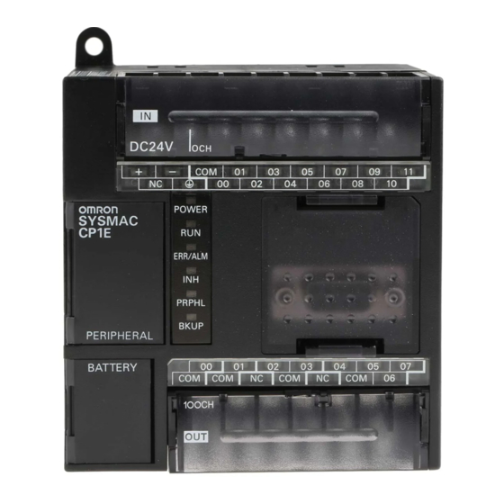
CP1E-E20DR-A
CP1E-N40DR-A
1
Advertisement
Table of Contents

Related Manuals for Omron SYSMAC CP1E-E20DR-A


Summary of Contents for Omron SYSMAC CP1E-E20DR-A
- Page 1 • Easy connection with computers using commercially available USB cables • With E30/40, N30/40/60 or NA20 CPU Units, Add I/O by Connecting Expansion I/O Units. • With E30/40, N30/40/60 or NA20 CPU Units, Add Analog I/O or Temperature Inputs by Connecting Expansion Units. • Quick-response inputs •...
-
Page 2: System Configuration
16 outputs Temperature sensors CompoBus/S I/O Link Unit 32 outputs Up to 3 Units can be connected When a two level layout is created by expansion and distance is required CP1E-E10D@-@ I/O Connecting Cable Expansion Units and CP1E-E14DR-A CP1E CPU Unit... -
Page 3: Ordering Information
International Standards • The standards are abbreviated as follows: U: UL, U1: UL (Class I Division 2 Products for Hazardous Locations), C: CSA, UC: cULus, UC1: cULus (Class I Division 2 Products for Hazardous Locations), CU: cUL, N: NK, L: Lloyd, and CE: EC Directives. - Page 4 CP1E-E@@D@-@ CP1E-N@@D@-@/NA20D@-@ N/NA-type CP1E CPU Units (Application Models) Current External Specifications consumption (A) power Product supply Model Standards Data name Power Output Program (24 VDC) Inputs Outputs memory 24 V Supply type capacity capacity N-type Available soon Relay 0.17 0.07...
- Page 5 Counter Present Values (C), Auxiliary Area (A), and Clock Function (Use batteries within two years of manufacture.) Note: There are no accessories included with N/NA-type CP1E CPU Units. RS-232C connectors for the built-in RS-232C port and the Battery (CP1W-BAT01) are not included.
-
Page 6: Programming Devices
Option Board Units only. CP1W-CIF12 N, L, CE Note: It is not possible to use a CP-series Ethernet Option Board (CP1W-CIF41), LCD Option Board (CP1W-DAM01), or Memory Card (CP1W- ME05M) with a CP1E CPU Unit. Programming Devices Specifications Product name... - Page 7 I/O Connecting Cable CP1W-CN811 UC1, N, L, CE Only one I/O Connecting Cable can be used in each PLC. Note: An I/O Connecting Cable (approx. 6 cm) for horizontal connection is provided with CP1W Expansion I/O Units and Expansion Units.
-
Page 8: General Specifications
* 3 Use the external power supply to power input devices. Do not use it to drive output devices. * 4 This is the rated value for the maximum system configuration. Use the following formula to calculate power consumption for CPU Units with DC power. -
Page 9: Performance Specifications
6 inputs (4 inputs only for 10 I/O points) Quick-response Inputs Input pulse width: 50 µs min. Input Delays can be set in the PLC Setup (0 to 32 ms, default: 8 ms). Normal input constants Set values: 0, 1, 2, 4, 8, 16, or 32 ms... - Page 10 1,600 bits (100 words): CIO 100.00 to CIO 199.15 (CIO 100 to CIO 199) Serial PLC Link Words 1,440 bits (90 words): CIO 200.00 to CIO 289.15 (words CIO 200 to CIO 289) Work Area (W) 1,600 bits (100 words): W0.00 to W99.15 (W0 to W99) 800 bits (50 words): H0.00 to H49.15 (H0 to H49)
-
Page 11: Function Specifications
Pulses for which the duty ratio (ratio between ON time and OFF time during one pulse (Models with transistor outputs only) cycle) can be set are output. Normal All of the outputs on the CPU Unit’s I/O can be turned OFF when an error occurs in RUN Load OFF function outputs or MONITOR mode. - Page 12 Holding Area data, DM Area data, Counter Completion Flags, and counter present values are held even when power is turned OFF. Memory protection Power supply This function can be used only with an N/NA-type CPU Unit and only when the Battery Set management (sold separately) is mounted. Number of power interruptions counter The number of times power has been interrupted is counted.
-
Page 13: Cpu Unit Memory Backup Structure
Create a system and write the ladder programs so that problems will not occur in the system if the data in these area may be unstable. • Data in areas such as the DM area (D), Holding Area (H), the Counter Present Values (C) and the status of Counter Completion Flags (C), which is retained by the battery, may be unstable when the power supply is turned off (Except for the DM area that are retained by the built-in EEP- ROM using the Auxilliary Area bit.) - Page 14 CP1E-E@@D@-@ CP1E-N@@D@-@/NA20D@-@ I/O Memory Areas Data can be read and written to I/O memory from the ladder programs. I/O memory consists of an area for I/O with external devices, user areas, and system areas. System Areas Input bits (starting from CIO 0)
-
Page 15: Backing Up And Restoring Dm Area Data
The contents of the specified words in the DM Area data can be backed up from RAM to the built-in EEPROM backup memory during operation by turning ON a bit in the Auxiliary Area. The number of DM Area words to back up is specified in the Number of CH of DM for backup Box in the PLC Setup. - Page 16 CP1E-E@@D@-@ CP1E-N@@D@-@/NA20D@-@ Built-in Inputs Terminal Arrangements ●Input Terminal Arrangement for CPU Unit with 10 I/O Points AC power supply models CIO 0 L1 L2/N COM 01 DC power supply models CIO 0 − COM 01 ●Input Terminal Arrangement for CPU Unit with 14 I/O Points...
- Page 17 L1 L2/N COM 01 DC power supply models CIO 0 CIO 1 CIO 2 − ●Input Terminal Arrangement for CPU Unit with 20 I/O Points and Built-in Analog AC power supply models CIO 0 CIO 90 CIO 91 L1 L2/N COM...
- Page 18 CP1E-E@@D@-@ CP1E-N@@D@-@/NA20D@-@ Allocating Built-in Inputs to Functions Input terminals are allocated functions by setting parameters in the PLC Setup. Set the PLC Setup so that each terminal is used for only one function. Settings in PLC Setup Input terminal block...
- Page 19 COM 03 COM 06 COM 01 03 COM 06 CIO 100 CIO 101 CIO 102 ●Output Terminal Arrangement for CPU Unit with 20 I/O Points and Built-in Analog AC power supply model DC power supply model IOUT0 NC IOUT0 −...
- Page 20 CP1E-E@@D@-@ CP1E-N@@D@-@/NA20D@-@ Allocating Built-in Output Terminals to Functions Output terminals are allocated functions by setting parameters in the PLC Setup. Set the PLC Setup so that each terminal is used for only one function. Setting in PLC Setup When a pulse output instruction...
-
Page 21: Input Specifications
* 1 The bits that can be used depend on the model of CPU Unit. * 2 The response time is the delay caused by hardware. The delay set in the PLC Setup (0 to 32 ms, default: 8 ms) for a normal input must be added to this value. -
Page 22: Output Specifications
24 VDC, 2 A max. Estimating the Service Life of Relays Under normal conditions, the service life of output contacts is as shown above. The service life of relays is as shown in the following diagram as a guideline CP1E-@@DR-@ 1000... - Page 23 4μs min. 2μs min. Note: 1. The load for the above values is assumed to be the resistance load, and does not take into account the impedance for the connecting cable to the load. 2. Due to distortions in pulse waveforms resulting from connecting cable impedance, the pulse widths in actual operation may be smaller than the values shown above.
- Page 24 2 inputs (Allocated 2 words: CIO 90 to CIO 91.) Input signal range 0 to 5 V, 1 to 5 V, 0 to 10 V, or -10 to 10 V 0 to 20 mA or 4 to 20 mA Max. rated input ±15 V...
-
Page 25: Expandable Cpu Units
40EDR Connection Methods Connection cables for the Expansion I/O Units and Expansion Units are used to connect the Units. The length can be extended by using a CP1W- CN811 I/O Connection Cable (length: 800 m). Maximum Number of I/O Points for an Expanded System... - Page 26 Note: Do not apply voltage in excess of the rated voltage to the input terminal. * The response time is the hardware delay value. The delay set in the PLC Setup (0 to 32 ms, default: 8 ms) must be added to this value. For the CP1W-40EDR/EDT/EDT1, a fixed value of 16 ms must be added.
- Page 27 Ambient temperature (˚C) 4. According to the ambient temperature, there are restrictions on power supply voltage and output load current for the CPU Units connected with the Expansion I/O Units (CP1W-8ER/16ER/20EDR1/32ER/40EDR). Use the PLC in the range of the power supply voltage and output load current as show below.
- Page 28 Ambient temperature *2 The fuse cannot be replaced by the user. Replace the Unit if the fuse breaks due to an short-circuit or overcurrent. *3 Do not connect a load to an output terminal or apply a voltage in excess of the maximum switching capacity.
-
Page 29: Analog Input Units
Supported Conversion time 2 ms/point (8 ms/all points) Isolation method Photocoupler isolation between analog I/O terminals and internal circuits. No isolation between analog I/O signals. Current consumption 5 VDC: 100 mA max.; 24 VDC: 90 mA max. ●Analog Output Units... - Page 30 5 VDC: 40 mA max., 24 VDC: 59 mA max. 5 VDC: 54 mA max., 24 VDC: 73 mA max. * Accuracy for a K-type sensor at -100°C or less is ±4°C ±1 digit max. The rotary switch is used to set the temperature range.
- Page 31 Connector hood Frame Ground Note: Do not use the 5-V power from pin 6 of the RS-232C port for anything but CJ1W-CIF11 RS-422A Conversion Adapter, NT-AL001 RS-232C/RS-422A Conversion Adapter and NV3W-M@20L Programmable Terminal. The external device or the CPU Unit may be damaged.
- Page 32 Connector hood Frame Ground Note: Do not use the 5-V power from pin 6 of the RS-232C port for anything but CJ1W-CIF11 RS-422A Conversion Adapter, NT-AL001 RS-232C/RS-422A Conversion Adapter and NV3W-M@20L Programmable Terminal. The external device or the CPU Unit may be damaged.
-
Page 33: Operating Environment And System Configuration
(Conforming to USB 2.0, B connector) Note: The CX-Programmer cannot be used if it is connected to the built-in RS-232C port or serial option port of a CP1E CPU Unit. * Commercially available USB cable: 5 m max., for USB 2.0. - Page 34 CP1E CPU Units CP1E-N@@D@-@ Unit version 1.@ CP1E-NA@@D@-@ Unit Versions and Programming Devices The following tables show the relationship between unit versions and CX-Programmer versions. Unit Versions and Programming Devices Required Programming Device * CX-Programmer Micro PLC Edition CX-Programmer Programmer...
-
Page 35: Programming Instructions
COMPARE MULTI-INTERLOCK CLEAR MILC TABLE COMPARE TCMP JUMP UNSIGNED BLOCK COMPARE BCMP JUMP END AREA RANGE COMPARE CONDITIONAL JUMP DOUBLE AREA RANGE COMPARE ZCPL FOR LOOP Data Movement Instructions BREAK LOOP BREAK NEXT LOOP NEXT Instruction Mnemonic MOVE Timer and Counter Instructions... -
Page 36: Data Shift Instructions
Mnemonic CARRY FLOATING TO 16-BIT DOUBLE SIGNED BINARY ADD WITHOUT CARRY FLOATING TO 32-BIT FIXL SIGNED BINARY ADD WITH CARRY +C 16-BIT TO FLOATING DOUBLE SIGNED BINARY ADD 32-BIT TO FLOATING FLTL WITH CARRY FLOATING-POINT ADD BCD ADD WITHOUT CARRY... -
Page 37: Subroutine Instructions
SUBROUTINE ENTRY SUBROUTINE RETURN Interrupt Control Instructions Instruction Mnemonic SET INTERRUPT MASK MSKS CLEAR INTERRUPT DISABLE INTERRUPTS ENABLE INTERRUPTS High-speed Counter and Pulse Output Instructions Instruction Mnemonic MODE CONTROL HIGH-SPEED COUNTER PV READ COMPARISON TABLE LOAD CTBL SPEED OUTPUT SPED... - Page 38 ●CPU Units with 10 I/O Points 110 100 Two, 4.5 dia. ●CPU Units with 14 or 20 I/O Points Two, 4.5 dia. ●CPU Units with 30 I/O Points CPU Units with 20 I/O Points and Built-in Analog Four, 4.5 dia.
- Page 39 CP1E-E@@D@-@ CP1E-N@@D@-@/NA20D@-@ ●CPU Units with 40 I/O Points Four, 4.5 dia. ●CPU Units with 60 I/O Points 110 100 Four, 4.5 dia.
- Page 40 CP1E-E@@D@-@ CP1E-N@@D@-@/NA20D@-@ Expansion I/O Units and Expansion Units ●CP1W-8E@@/CP1W-SRT21 56 ± 0.2 100 ± 0.2 Two, 4.5 dia. ●CP1W-20ED@/CP1W-16E@@/CP1W-AD041/CP1W-DA041/CP1W-MAD11/CP1W-TS@@@ 76 ± 0.2 100 ± 0.2 Two, 4.5 dia. ●CP1W-40ED@/CP1W-32E@@ Four, 4.5 dia.
-
Page 41: Related Manuals
CPU Unit Hardware Manual • Installation and settings CP1E-NA@@D@-@ • Troubleshooting Use this manual together with the CP1E CPU Unit Software Manual (Cat. No. W480) and CP1E CPU Unit Instructions Reference Manual (Cat. No. W483). Describes the following information for CP1E PLCs. - Page 42 MEMO...
- Page 43 CONTRACT, WARRANTY, NEGLIGENCE, OR STRICT LIABILITY. In no event shall the responsibility of OMRON for any act exceed the individual price of the product on which liability is asserted. IN NO EVENT SHALL OMRON BE RESPONSIBLE FOR WARRANTY, REPAIR, OR OTHER CLAIMS REGARDING THE...
- Page 44 Note: Do not use this document to operate the Unit. OMRON Corporation Industrial Automation Company Authorized Distributor: Tokyo, JAPAN Contact: www.ia.omron.com Regional Headquarters OMRON EUROPE B.V. OMRON ELECTRONICS LLC Wegalaan 67-69-2132 JD Hoofddorp One Commerce Drive Schaumburg, The Netherlands IL 60173-5302 U.S.A.