
Related Manuals for Omron CP1E Series


Summary of Contents for Omron CP1E Series
- Page 1 Cat. No. W479-E1-01 SYSMAC CP Series CP1E-E@@D@-A CP1E-N@@D@-@ CP1E CPU Unit Hardware USER’S MANUAL...
- Page 2 OMRON. No patent liability is assumed with respect to the use of the information contained herein. Moreover, because OMRON is con- stantly striving to improve its high-quality products, the information contained in this manual is subject to change without notice.
- Page 3 SYSMAC CP Series CP1E-E@@D@-A CP1E-N@@D@-@ CP1E CPU Unit Hardware User’s Manual Revised March 2009...
-
Page 5: Introduction
Introduction Thank you for purchasing a SYSMAC CP-series CP1E Programmable Controller. This manual contains information required to use the CP1E. Read this manual completely and be sure you understand the contents before attempting to use the CP1E. Intended Audience This manual is intended for the following personnel, who must also have knowledge of electrical sys- tems (an electrical engineer or the equivalent). - Page 6 CS/CJ/CP Series CS Series CJ Series CP Series CS1-H CPU Units CJ1-H CPU Units CP1E CPU Units CS1H-CPU CJ1H-CPU CP1E-E D -A CS1G-CPU CJ1G-CPU CP1E-N CJ1G-CPU (Loop CPU Unit) CS1 CPU Units CP1L CPU Units CS1H-CPU (-V1) CJ1M CPU Unit CP1L-L CS1G-CPU (-V1)
-
Page 7: Cp1E Cpu Unit Manuals
CP1E CPU Unit Manuals Information on the CP1E CPU Units is provided in the following manuals. Refer to the appropriate manual for the information that is required. This Manual CP1E CPU Unit Hardware CP1E CPU Unit Instructions CP1E CPU Unit Software User’s Manual(Cat. - Page 8 Manual Configuration The CP1E CPU manuals are organized in the sections listed in the following tables. Refer to the appro- priate section in the manuals as required. CP1E CPU Unit Hardware User’s Manual (Cat. No. W479) (This Manual) Section Contents Section 1 Overview and Specifica- This section gives an overview of the CP1E, describes its features, and tions...
- Page 9 Section Contents Section 11 Quick-response Inputs This section describes the quick-response inputs that can be used to read signals that are shorter than the cycle time. Section 12 Interrupts This section describes the interrupts that can be used with CP1E PLCs, including input interrupts and scheduled interrupts.
-
Page 10: Manual Structure
Manual Structure Page Structure and Icons The following page structure and icons are used in this manual. Level 1 heading 5 Installation and wiring Level 2 heading Level 3 heading Installation Level 2 heading Gives the current headings. Level 3 heading 5-2-1 Installation Location DIN Track Installation... - Page 11 Sections in this Manual Overview and Appendices Specifications Basic System Configuration and Devices Part Names and Functions Programming Device Installation and Wiring Troubleshooting Maintenance and Inspection Backup Operations Using Expansion Units and Expansion I/O Units CP1E CPU Unit Hardware User’s Manual(W479)
-
Page 12: Table Of Contents
CONTENTS Introduction ....................... 1 CP1E CPU Unit Manuals ................... 3 Manual Structure ....................... 6 Safety Precautions ....................15 Precautions for Safe Use..................20 Operating Environment Precautions ..............25 Regulations and Standards..................26 Related Manuals ...................... 27 Section 1 Overview and Specifications CP1E Overview ........................ - Page 13 3-1-1 CPU Units with 20 I/O Points ...................... 3-2 3-1-2 CPU Units with 30 or 40 I/O Points ..................... 3-6 3-1-3 Common I/O Specifications....................... 3-11 3-1-4 Optional Serial Communications Board for N-type CPU Units with 30 or 40 I/O Points ... 3-16 Expansion I/O Units.......................
- Page 14 Section 7 Maintenance and Inspection Periodic Maintenance and Inspection ................... 7-2 7-1-1 Tools Required for Inspections ....................7-2 7-1-2 Periodic Inspection........................7-2 7-1-3 Inspection and Maintenance ....................... 7-3 7-1-4 Unit Replacement Precautions....................7-4 Replacing the Battery in N-type CPU Units................7-5 Section 8 Backup Operations Section 9...
- Page 15 A-3-1 CPU Units ..........................A-13 A-3-2 Expansion I/O Units ........................A-16 A-3-3 Expansion Units........................A-23 A-3-4 Serial Communications......................A-28 A-4 Wiring for Serial Communications..................A-33 A-4-1 Recommended RS-232C Wiring ....................A-33 A-4-2 Recommended RS-422A/485 Wiring ..................A-36 A-4-3 Converting the Built-in RS-232C Port to RS-422A/485 ............A-37 A-4-4 Reducing Electrical Noise for External Wiring ................
- Page 16 WHETHER SUCH CLAIM IS BASED ON CONTRACT, WARRANTY, NEGLIGENCE, OR STRICT LIABILITY. In no event shall the responsibility of OMRON for any act exceed the individual price of the product on which liability is asserted. IN NO EVENT SHALL OMRON BE RESPONSIBLE FOR WARRANTY, REPAIR, OR OTHER CLAIMS REGARDING THE PRODUCTS UNLESS OMRON’S ANALYSIS CONFIRMS THAT THE PRODUCTS...
- Page 17 Application Considerations SUITABILITY FOR USE OMRON shall not be responsible for conformity with any standards, codes, or regulations that apply to the combination of products in the customer’s application or use of the products. At the customer’s request, OMRON will provide applicable third party certification documents identifying ratings and limitations of use that apply to the products.
- Page 18 Performance data given in this manual is provided as a guide for the user in determining suitability and does not constitute a warranty. It may represent the result of OMRON’s test conditions, and the users must correlate it to actual application requirements. Actual performance is subject to the OMRON Warranty and Limitations of Liability.
-
Page 19: Safety Precautions
Safety Precautions Definition of Precautionary Information The following notation is used in this manual to provide precautions required to ensure safe usage of a CP-series PLC. The safety precautions that are provided are extremely important to safety. Always read and heed the information provided in all safety precautions. Indicates an imminently hazardous situation which, WARNING if not avoided, will result in death or serious injury. - Page 20 Symbols The triangle symbol indicates precautions (including warnings). The specific operation is shown in the triangle and explained in text. This example indicates a precau- tion for electric shock. The circle and slash symbol indicates operations that you must not do. The specific operation is shown in the circle and explained in text.
- Page 21 WARNING Do not attempt to take any Unit apart while the power is being supplied. Doing so may result in electric shock. Do not touch any of the terminals or terminal blocks while the power is being supplied. Doing so may result in electric shock. Provide safety measures in external circuits (i.e., not in the Programmable Con- troller), including the following items, to ensure safety in the system if an abnormality occurs due to malfunction of the PLC or another external factor...
- Page 22 Caution Caution Be sure to sufficiently confirm the safety at the destination when you transfer the program or I/O memory or perform procedures to change the I/O memory. Devices connected to PLC outputs may incorrectly operate regardless of the operat- ing mode of the CPU Unit.
- Page 23 Caution Pay careful attention to the polarities (+/-) when wiring the DC power supply. A wrong connection may cause malfunction of the system. When connecting the PLC to a computer or other peripheral device, either ground the 0-V side of the external power supply or do not ground the external power supply at all.
-
Page 24: Precautions For Safe Use
Precautions for Safe Use Observe the following precautions when using a CP-series PLC. Power Supply • Always use the power supply voltages specified in the user’s manuals. An incorrect voltage may result in malfunction or burning. • Take appropriate measures to ensure that the specified power with the rated voltage and fre- quency is supplied. - Page 25 • Be sure that all the PLC terminal screws and cable connector screws are tightened to the torque specified in the relevant manuals. The tightening torque for the terminals on the CP1W- CIF11/CIF12 terminal block is 0.28 N·m Incorrect tightening torque may result in malfunction. •...
- Page 26 • Clearing Specific Bits in the Held Areas at Startup Use the following type of ladder programming. Example P_First_Cycle BSET D100 to D2047 are cleared to Zero #0000 First Cycle Flag (A200.11) D100 D2047 H10 to H49 are cleared BSET to Zero #0000 C0 to C255 are cleared...
- Page 27 2. Include programming to back up specified words in the DM Area to built-in EEPROM by turning ON A751.15 (DM Backup Save Start Bit). Execution condition A751.15 Bit is turned ON to start backup. DM Backup Save Start Bit • Refer to 3-2 Memory Backup in the CP1E CPU Unit Software User’s Manual (Cat.
- Page 28 • Never short-circuit the positive and negative terminals of a battery or charge, disassemble, heat, or incinerate the battery. Do not subject the battery to strong shocks or deform the battery by applying pressure. Doing any of these may result in leakage, rupture, heat generation, or ignition of the battery.
-
Page 29: Operating Environment Precautions
Operating Environment Precautions Follow the instructions in this manual to correctly perform installation. Do not operate the control system in the following locations: • Locations subject to direct sunlight • Locations subject to temperatures or humidity outside the range specified in the specifications •... -
Page 30: Regulations And Standards
Concepts EMC Directives OMRON devices are electrical components that are designed to be built into equipment and manu- facturing systems. OMRON devices that comply with EMC Directives also conform to the related EMC standards (see note.), so that they can be more easily built into other devices or the overall machine. -
Page 31: Related Manuals
Related Manuals The following manuals are related to the CP1E. Use them together with this manual. Manual name Cat. No. Model numbers Application Contents SYSMAC CP Series W479 CP1E-E D -A To learn the hard- Describes the following information for CP1E CP1E CPU Unit Hard- ware specifications PLCs. - Page 32 CP1E CPU Unit Hardware User’s Manual(W479)
-
Page 33: Overview And Specifications
Overview and Specifications This section gives an overview of the CP1E, describes its features, and provides its specifications. 1-1 CP1E Overview ..........1-2 1-1-1 Overview of Features . -
Page 34: Cp1E Overview
1-1-1 Overview of Features The SYSMAC CP1E Programmable Controller is a package-type PLC made by OMRON that is designed for easy application. The CP1E includes E-type CPU Units (basic models) for standard con- trol operations using basic, movement, arithmetic, and comparison instructions, and N-type CPU Units (application models) that supports connections to Programmable Terminals, Inverters, and Servo Drives. -
Page 35: Features
1 Overview and Specifications Precautions for Correct Use Precautions for Correct Use For CP1E CPU Units, the following I/O memory area will be unstable after a power interruption. • DM Area (D) (excluding words backed up to the EEPROM using the DM function) •... - Page 36 1 Overview and Specifications With CPU Units with 30 or 40 I/O Points, Add I/O by Connecting Expansion I/O Units A total of up to three of the following Expansion I/O Units can be connected to a CPU Unit with 30 or 40 I/O points.
-
Page 37: Input Interrupts
1 Overview and Specifications Input Interrupts An interrupt task can be started when a built-in input turns ON or turns OFF . Up to six interrupt inputs can be used. Interrupt input Built-in input Interrupt task Ladder program Interrupt occurs Note The user setting in the PLC Setup determines if each input is a quick-response input, normal input, interrupt input, or high-speed counter input. - Page 38 1 Overview and Specifications Versatile Pulse Control for N-type CPU Units Fixed duty ratio pulse outputs can be output from the CPU Unit’s built-in outputs and used to perform positioning or speed control with a servomotor or a stepping motor that accepts pulse inputs. Two pulse outputs at 100 kHz are provided as standard features.
- Page 39 1 Overview and Specifications Analog Settings By adjusting the analog adjuster with a Phillips screwdriver, the value in the Auxiliary Area (A642) can be changed to any value between 0 and 255. All CPU Units are equipped with two analog adjusters. This makes it easy to change set values, such as those for timers and counters, without a Programming Device.
- Page 40 1 Overview and Specifications Mounting Serial Option Boards to N-type CPU Units with 30 or 40 I/O Points One Serial Communications Option Board with one RS-232C port or one RS-422A/485 port can be added to an N-type CPU Unit with 30 or 40 I/O points. With the serial communications port, it is easy to connect to general components, such as barcode readers, and other components such as PTs, other CP-series PLCs, and Inverters.
-
Page 41: Basic Operating Procedure
1 Overview and Specifications Basic Operating Procedure In general, use the following procedure. 1. Setting Devices and Hardware Connect the CPU Unit, Expansion I/O Units, and Expansion Units. Set the DIP switches on the Option Board and Expansion Units as required. Refer to Section 3 Part Names and Functions and Section 5 Installation and Wiring in the CP1E CPU Unit Hardware User’s Manual (Cat. -
Page 42: Specifications
1 Overview and Specifications Specifications 1-3-1 General Specifications The following table lists the general specifications of CP1E CPU Units. Item AC power supply DC power supply Model CP1E- CP1E-N Enclosure Mounted in a panel Dimensions (H × D × W) CPU Unit with 20 I/O points (CP1E- 20D - ) : 90mm* ×85mm*... -
Page 43: Characteristics
1 Overview and Specifications 1-3-2 Characteristics The following table gives the characteristics of CP1E CPU Units. CP1E- Item E20DR-A E30DR-A E40DR-A N20D - N30D - N40D - Program capacity 2K steps (8 KB) including the symbol table, comments, 8K steps (32 KB) including the symbol table, com- and program indices of the CX-Programmer for CP1E ments, and program indices of the CX-Programmer for CP1E... - Page 44 1 Overview and Specifications CP1E- Item E20DR-A E30DR-A E40DR-A N20D - N30D - N40D - Built-in RS-232C port No built-in RS-232C port Interface: Conforms to EIA RS-232C. Communica Communica- Half duplex tions tions method Synchroniza- Start-stop tion Baud rate 1.2, 2.4, 4.8, 9.6, 19.2, 38.4, 57.6, or 115.2 kbps Transmission 15 m max.
-
Page 45: Functional Specifications
1 Overview and Specifications 1-3-3 Functional Specifications The following table gives the functional specifications of CP1E CPU Units. Function Description Cycle time Minimum cycle time Makes the cycle time consistent. manage- Monitoring the cycle time Monitors the cycle time. ment CPU Unit Inputs High-... - Page 46 1 Overview and Specifications Function Description Power sup- Memory protection Holding Area data, DM Area data, EM Area data, Counter Completion Flags, ply man- and counter present values are held even when power is turned OFF. agement This function is valid only when an optional battery is mounted. Number of power interruptions counter The number of times power has been interrupted is counted.
-
Page 47: Basic System Configuration And Devices
Ü Basic System Configuration and Devices This section describes the basic system configuration and device models of the CP1E. 2-1 Basic System Configuration ........2-2 2-1-1 Basic System Configuration Using an E-type CPU Unit . -
Page 48: Basic System Configuration
2 Basic System Configuration and Devices Basic System Configuration This section describes the system configurations using E-type and N-type CP1E CPU Units. 2-1-1 Basic System Configuration Using an E-type CPU Unit The system configuration when using a CP1E E-type CPU Unit is shown below. CP1E CPU Unit Expansion I/O Units Expansion Units... -
Page 49: Basic System Configuration Using An N-Type Cpu Unit
2 Basic System Configuration and Devices 2-1-2 Basic System Configuration Using an N-type CPU Unit The system configuration when using a CP1E N-type CPU Unit is shown below. Battery CP1W-BAT01 CP1E CPU Unit Expansion I/O Units Expansion Units DIN Track CPU Unit with 30 or 40 I/O Point CPU Unit with 20 or 40 I/O Points Analog I/O... -
Page 50: Cpu Units
2 Basic System Configuration and Devices CPU Units This section describes the models of CP1E CPU Units. 2-2-1 CPU Unit Models The CP1E CPU Unit model numbers are configured as shown below. Power supply A: AC power supply CP1E- D -A D: DC power supply Output type R: Relays outputs... - Page 51 2 Basic System Configuration and Devices Number of built-in I/O points Power supply Program Name and appearance Model number Output type Area Weight Number Number specifica- capacity Total capacity of inputs of outputs tions N-type CPU Units CP1E-N20DR-A AC power Relays Less than supply...
-
Page 52: Optional Products
2 Basic System Configuration and Devices 2-2-2 Optional Products Optional Products for CPU Units Current consumption Name and appearance Model number Applications Weight DC5V DC24V − RS-232C Option Board CP1W-CIF01 Mounted in the option slot of an N-type CPU Includ- Includ- Unit with 30 or 40 I/O points and can be used ing in... -
Page 53: Unit Versions Of Cpu Units
CP1E CPU Unit Product nameplate CP1E-N40DR-A CPU UNIT Lot No. 28705 0000 Ver.1.0 OMRON Corporation MADE IN CHINA Lot No. Unit version (example for unit version 1.0) Confirming Unit Versions with Support Software CX-Programmer for CP1E can be used to confirm the unit version of the CP1E CPU Units. - Page 54 2 Basic System Configuration and Devices Unit Versions Type Model numbers Unit version CP1E CPU Units CP1E-E D -A Unit version 1.0 CP1E-N Unit Versions and Support Software The relationship between the unit versions of CP1E CPU Units and versions of Support Software is shown below.
-
Page 55: Expansion I/O Unit Or Expansion Unit
2 Basic System Configuration and Devices Expansion I/O Unit or Expansion Unit This section describes the connection of Expansion I/O Units or Expansion Units to a CP1E CPU Unit. 2-3-1 Expandable CPU Units • Expansion I/O Units and Expansion Units cannot be connected to an E-type or N-type CPU Units with 20 I/O points. -
Page 56: Expansion I/O Units And Expansion Units
2 Basic System Configuration and Devices 2-3-4 Expansion I/O Units and Expansion Units Expansion I/O Units Current Specifications consumption Name and appearance Model number Weight Outputs Inputs − 8-point Input Unit CP1W-8ED Not provided. 8 inputs, 24 VDC 0.018A 200g 8-point Output Units CP1W-8ER 8 relay outputs... -
Page 57: Expansion Units
2 Basic System Configuration and Devices Expansion Units Current consumption Name and appearance Model number Specifications Weight Analog I/O Unit CP1W-MAD11 2 analog inputs 0.083A 0.110A 250g 0 to 5 V, 1 to 5 V, 0 to 10 V, -10 to 10 V, 0 to 20 mA, and 4 to 20 mA 1 analog output 1 to 5 V, 0 to 10 V, -10 to 10 V, 0 to 20 mA, 4... -
Page 58: I/O Allocation To Expansion Units And Expansion I/O Units
2 Basic System Configuration and Devices 2-3-5 I/O Allocation to Expansion Units and Expansion I/O Units Expansion Units and Expansion I/O Units can be connected to the CP1E. Up to three Expansion Units or Expansion I/O Units can be connected to a CPU Unit with 30 or 40 I/O points. -
Page 59: Restrictions On System Configuration
2 Basic System Configuration and Devices Allocation of I/O Words Expansion Units and Expansion I/O Units are allocated I/O bits in the order the Units are connected starting from the CP1E CPU Unit. When the power to the CPU Unit is turned ON, the CPU Unit checks for any Expansion Units and Expansion I/O Units connected to it and automatically allocates I/O bits. - Page 60 2 Basic System Configuration and Devices Restrictions by ambient temperature According to the ambient temperature, there are restrictions on power supply voltage and output load current for the DC-power-supply CPU Units. Refer to Output Specifications for Relay Outputs in 3-1-3 Common I/O Specifications and in 3-2-4 I/O Specifications for Expansion I/O Units for details.
-
Page 61: Unit Current Consumption And External Power Supply Capacity
2 Basic System Configuration and Devices Unit Current Consumption and External Power Supply Capacity This section describes the current consumption and external power supply capacity of units used by the CP1E. 2-4-1 External Power Supply Capacity When Expansion I/O Units or Expansion Units are Connected Power of 24 VDC can be supplied to external devices from CPU Units with 30 or 40 I/O points. -
Page 62: Current Consumption
2 Basic System Configuration and Devices 2-4-2 Current Consumption CPU Units E-type CPU Units Current consumption I/O capacity Model number 5 VDC 24 VDC 20 I/O points CP1E-E20DR-A 0.17A 0.08A 30 I/O points CP1E-E30DR-A 0.17A 0.07A 40 I/O points CP1E-E40DR-A 0.17A 0.09A N-type CPU Units... - Page 63 2 Basic System Configuration and Devices Expansion I/O Units and Expansion Units Current consumption Unit name Model number 5 VDC 24 VDC − Expansion I/O Units 8 inputs CP1W-8ED 0.018A 8 outputs CP1W-8ER 0.026A 0.044A − CP1W-8ET 0.075A CP1W-8ET1 16 outputs CP1W-16ER 0.042A 0.090A...
- Page 64 2 Basic System Configuration and Devices 2-18 CP1E CPU Unit Hardware User’s Manual(W479)
- Page 65 Part Names and Functions This section describes the part names, function specifications and terminal arrange- ments of the CP1E CPU Unit and other Units. 3-1 CPU Units ........... . 3-2 3-1-1 CPU Units with 20 I/O Points .
-
Page 66: Cpu Units With 20 I/O Points
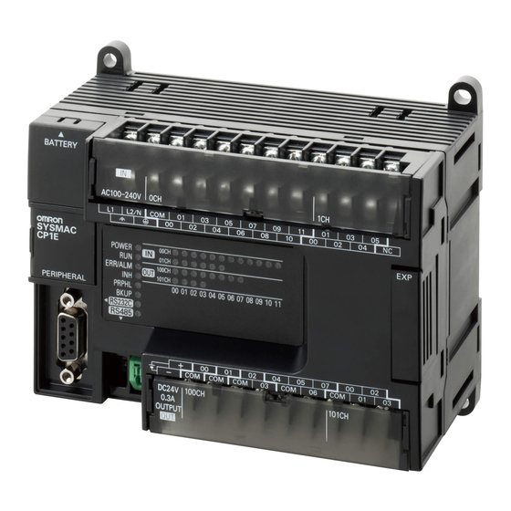
3 Part Names and Functions CPU Units This section describes the names of the CPU Unit parts and provides the I/O specifications and termi- nal arrangements. Refer to A-2 Dimensions for the dimensions, A-3 Wiring Diagrams for the wiring diagrams. 3-1-1 CPU Units with 20 I/O Points Part Names and Functions... - Page 67 3 Part Names and Functions CPU Unit Status Indicators : Not lit : Flashing : Lit Indicator Color Status Description POWER Green Power is ON. POWER Power is OFF. Not lit Green The CP1E is executing a program in either RUN or MONITOR mode.
- Page 68 3 Part Names and Functions Terminal Arrangements Input Arrangement AC Power Supply CIO 0 L1,L2/N : Power supply terminal L1 L2/N COM 01 : Protective ground terminal : Common terminal 00 to 11 : Input terminal : No connection DC Power Supply : External supply terminal COM 01 : Protective ground terminal...
- Page 69 3 Part Names and Functions Allocating Functions to Built-in I/O Terminals The CP1E built-in I/O terminals are allocated functions by setting parameters in the PLC Setup. Set the PLC Setup so that each terminal is used for only one function. Allocating Functions to Built-in Input Terminals PLC Setup Origin search...
-
Page 70: Cpu Units With 30 Or 40 I/O Points
3 Part Names and Functions 3-1-2 CPU Units with 30 or 40 I/O Points Part Names and Functions E-type CPU Unit N-type CPU Unit CP1E-E30/40DR-A CP1E-N30/40D - Power supply Built-in RS-232C communications Input terminals input terminals status indicator Input terminal block Battery Ground... - Page 71 3 Part Names and Functions Number Name Function Built-in RS-232C communi- This indicator will be flashing if the built-in RS-232C port is in communi- cations status indicator cation mode. Option Board slot for N-type An Option Board can be connected to the slot. CPU Units ·...
- Page 72 3 Part Names and Functions Terminal Arrangements Input Arrangement AC Power Supply CP1E- 30D -A CIO 0 CIO 1 L1 L2/N COM L1,L2/N : Power supply terminal : Functional ground terminal : Protective ground terminal CP1E- 40D -A : Common terminal 00 to 11 : Input terminal CIO 0 CIO 1...
- Page 73 3 Part Names and Functions Output Arrangement AC Power Supply CP1E- 30D -A CIO 100 CIO 101 : External supply terminal CP1E- 40D -A : Common terminal 00 to 07 : Output terminal COM COM 07 COM CIO 100 CIO 101 DC Power Supply CP1E-N30D -D COM COM COM...
- Page 74 3 Part Names and Functions Allocating Functions to Built-in I/O Terminals The CP1E built-in I/O terminals are allocated functions by setting parameters in the PLC Setup. Set the PLC Setup so that each terminal is used for only one function. Allocating Functions to Built-in Input Terminals PLC Setup Origin search...
-
Page 75: Common I/O Specifications
3 Part Names and Functions Allocating Functions to Built-in Output Terminals PLC Setup When a pulse output When the PWM Output terminal Other than those instruction (SPED, ACC, Origin search settings on CPU Unit instruction is block shown at the right PLS2, or ORG) is exe- Pulse Output 0/1 Tab executed... - Page 76 3 Part Names and Functions Item Specification Circuit E-type CPU Unit N-type CPU Unit configuration Inputs: CIO 0.00 to CIO 0.07 Inputs: CIO 0.00, CIO 0.01 Input indicator Input indicator 1000pF 1000pF Internal 3.3kΩ Internal 3.3kΩ circuits circuits Inputs: CIO 0.08 to CIO 0.11 and CIO 1.00 to CIO 1.11 Inputs: CIO 0.02 to CIO 0.07 Input indicator...
- Page 77 3 Part Names and Functions Estimating the Service Life of Relays Under normal conditions, the service life of output contacts is as shown above. The service life of relays is as shown in the following diagram as a guideline. CP1E- 20DR- CP1E- 30/40DR- 125-VAC resistive load 30-VDC/250-VAC resistive load...
-
Page 78: Normal Outputs
3 Part Names and Functions Output Specifications for Transistor Outputs (Sinking or Sourcing) CP1E-N30/40DT(1)-A, CP1E- N20DT(1)-A Normal Outputs Specification Item CIO 100.02 to CIO 100.07 and CIO 100.00 and CIO 100.01* CIO 101.00 to CIO 101.07* Maximum 0.3 mA/output, 0.9 A/common CP1E-N20D - : 1.8 A Unit switching 4.5 to 30 VDC... - Page 79 3 Part Names and Functions Pulse Outputs (CIO 100.00 and CIO 100.01) Item Specification Maximum switching capacity 100 mA 4.5 to 26.4 VDC Minimum switching capacity 7 mA 4.5 to 26.4 VDC Maximum output frequency 100 kHz Output waveform OFF 90 % 10 % 4µs min.
-
Page 80: Optional Serial Communications Board For N-Type Cpu Units With 30 Or 40 I/O Points
3 Part Names and Functions 3-1-4 Optional Serial Communications Board for N-type CPU Units with 30 or 40 I/O Points The Option Board can be mounted in the option slot of a CP1E N-type CPU Unit with 30 or 40 I/O Points. - Page 81 3 Part Names and Functions CP1W-CIF01 RS-232C Option Board Front Rear Communications status indicator CPU Unit connector COMM RS-232C connector RS-232C Connector Abbr. Signal Signal direction − Frame ground SD(TXD) Send data Outputs RD(RXD) Receive data Inputs RS(RTS) Request to send Outputs CS(CTS) Clear to send...
- Page 82 3 Part Names and Functions DIP switch for operation settings Setting ON (both ends) Terminating resistance selection 2-wire connections 2-wire or 4-wire selection* 4-wire connections 2-wire connections 2-wire or 4-wire selection* 4-wire connections − − Not used. RS control enabled RS control selection for RD* RS control disabled (Data always received.)
-
Page 83: Expansion I/O Units
3 Part Names and Functions Expansion I/O Units This section describes the names of the Expansion I/O Unit parts and provides the input specifications and terminal arrangement. Refer to A-2 Dimensions for the dimensions, A-3 Wiring Diagrams for the wiring diagrams. 3-2-1 Expansion Input Unit Part Names and Functions... -
Page 84: Expansion Output Units
3 Part Names and Functions 3-2-2 Expansion Output Units Part Names and Functions 8-point Output Units 16-point Output Units CP1W-8ER/8ET/8ET1 CP1W-16ER/ET/ET1 Output terminals Output terminals Expansion I/O Expansion I/O connecting cable connecting cable Output indicators Output indicators 00 01 02 03 04 05 06 07 Expansion connector 16ER Expansion connector... - Page 85 3 Part Names and Functions Terminal Arrangements The first word of output words allocated to the Expansion Output Unit is indicated by CIO n. 8-point Output Units (CP1W-8E ) • CP1W-8ER (Relay Outputs) Unit Upper Terminal Block Unit Lower Terminal Block : Common terminal 00 to 07 : Output terminal...
- Page 86 3 Part Names and Functions • CP1W-16ET1 (Sourcing Transistor Outputs) Unit Upper Terminal Block Unit Lower Terminal Block COM COM COM CIO n+1 CIO n : Common terminal 00 to 07 : Output terminal : No connection Units with 32 Output Points (CP1W-32E ) •...
-
Page 87: Expansion I/O Units
3 Part Names and Functions Unit Upper Terminal Block CIO n CIO n+1 COM COM COM COM CIO n+1 CIO n Unit Lower Terminal Block CIO n+2 CIO n+3 COM COM COM COM CIO n+2 CIO n+3 : Common terminal 00 to 07 : Output terminal : No connection... - Page 88 3 Part Names and Functions The first word of input words allocated to the Expansion I/O Unit is indicated by CIO m and the first word of the output words by CIO n. 20-point I/O Units (CP1W-20ED ) • Input (Unit Upper Terminal Block) : Common terminal 00 to 11 : Input terminal...
-
Page 89: I/O Specifications For Expansion I/O Units
3 Part Names and Functions 3-2-4 I/O Specifications for Expansion I/O Units This section describes the I/O specifications common to all Expansion I/O Units. I/O Specifications Input Specifications (CP1W-8ED/20EDR1/20EDT/20EDT1/40EDR/40EDT/40EDT1) Item Specification Input voltage 24 VDC, +10%, -15% Input impedance 4.7 kΩ Input current 5 mA typical ON voltage... - Page 90 3 Part Names and Functions Output Specifications for Relay Outputs (CP1W-8ER/16ER/20EDR1/32ER/40EDR) Item Specification Maximum switching capacity 2 A 250 VAC (cosφ = 1), 2 A 24 VDC (4 A/common) Minimum switching capacity 10 mA 5 VDC Service Electrical Resistive 150,000 operations (24 VDC) life of load relay...
- Page 91 3 Part Names and Functions • CP1W-32ER’s maximum number of simultaneously ON output points is 24 (75%). Relation between Number of ON Outputs and Ambient Temperature (CP1W-32ER) Number of inputs ON simultaneously (%) Ambient temperature (˚C) Output Specifications for Transistor Outputs (Sinking or Sourcing) Specification Item CP1W-32ET...
- Page 92 3 Part Names and Functions *1 If the ambient temperature is maintained below 50ºC, up to 0.9 A/common can be used. 50 55 (˚C) Ambient temperature *2 The fuse cannot be replaced by the user. Replace the Unit if the fuse breaks due to an short-circuit or overcur- rent.
-
Page 93: Expansion Units
3 Part Names and Functions Expansion Units For an overview, the names of parts, the specifications, and application methods for Expansion Units, Refer to Section 9 Using Expansion Units and Expansion I/O Units. Refer to A-2 Dimensions for the dimensions, A-3 Wiring Diagrams for the wiring diagrams. CP1E CPU Unit Hardware User’s Manual(W479) 3-29... - Page 94 3 Part Names and Functions 3-30 CP1E CPU Unit Hardware User’s Manual(W479)
- Page 95 Programming Device This section describes the features of the CX-Programmer for CP1E used for program- ming and debugging PLCs, as well as how to connect the PLC with the Programming Device. 4-1 CX-Programmer for CP1E ........4-2 4-1-1 Applicable Programming Devices .
-
Page 96: Cx-Programmer For Cp1E
4 Programming Device CX-Programmer for CP1E A programming device is a software application for initializing, programming, monitoring, and debug- ging PLCs. This section describes the programming device used by CP1E. 4-1-1 Applicable Programming Devices The CX-Programmer for CP1E shown below is used to program and monitor the CP1E Unit. IBM PC/AT or equivalent CX-Programmer... -
Page 97: Cx-Programmer For Cp1E
4 Programming Device 4-1-2 CX-Programmer for CP1E CX-Programmer for CP1E The CX-Programmer for CP1E is a basic software application for creating and debugging PLC pro- grams. Programming Tasks Ladder diagrams Programming functions Simulation Monitoring Debugging and maintenance functions CX-Programmer for CP1E PLC Setup CPU Unit parameters 4-1-3... - Page 98 4 Programming Device Smart Input Mode That Automatically Displays Candidates Automatic Instruction Candidate Function When the first letter of the instruction mnemonic is input, possible instructions are automatically dis- played. Example: Press the M Key. Instructions starting with “M” will be displayed. Automatic Address Increment Function The addresses of inputs and outputs are incremented by 1 starting from CIO 0.00 and CIO 100.00, respectively.
- Page 99 4 Programming Device Automatic Symbol Candidate Function When inputting symbol names, symbol candidates are automatically displayed based on the first let- ter. Example: Enter “L”. The symbols with names that start with an “L” are displayed in a list. Instructions Can Be Copied with Automatic Address Incrementing Automatic Address Incrementing A copied group of ladder instructions can be pasted with a specified address offset (e.g., 16 bits).
-
Page 100: Installing The Software
4 Programming Device 4-1-5 Installing the Software This section provides a simple description of how to install the CX-Programmer for CP1E on the hard disk of a computer. Preparing for Installation Check the following items before beginning with the installation. Available Hard Disk Space The CX-Programmer for CP1E can be installed on the hard disk only. -
Page 101: Connecting By Usb
4 Programming Device Connecting by USB This section describes how to connect a computer running the CX-Programmer for CP1E and the CP1E CPU Unit. 4-2-1 Connecting by USB Preparations for Connection The USB driver must be installed in the computer to connect the PLC to the computer using the USB port. -
Page 102: Installing The Usb Driver For Cp1E
CP1E to the computer via USB. The USB driver for CP1E is automatically stored in the following directory in the personal computer when the CX-Programmer for CP1E is installed: C:\Program Files\OMRON\CX-Server\USB\w2k\inf When the personal computer is connected to the CP1E by USB cable, the personal computer automat- ically recognizes the device and the USB driver installation is started. - Page 103 Option and select the Include the next location Check Box. Check that C:\Program Files\ OMRON\CX-Server\USB\ Win2000_XP\Inf is displayed and click the Next Button. The wizard will begin installing the driver. When installation has been completed, an Installation Complete Dialog Box will be displayed.
- Page 104 The Device Manager Dialog Box will be displayed. Double-click the USB (Universal Serial Bus) Controller Device. Check that OMRON SYSMAC PLC Device is displayed. If it appears, then the USB driver has been installed correctly. Close the Device Manager Dialog Box and System Properties Dialog Box.
- Page 105 4 Programming Device Restrictions on Connecting by USB The following restrictions apply to the connection of the CP1E to a computer due to the USB specifica- tions. Keep these restrictions in mind when using the USB port. • Only one CP1E CPU Unit can be connected by USB to a single personal computer. It is not possible to connect multiple CP1E CPU Units simultaneously.
- Page 106 4 Programming Device 4-12 CP1E CPU Unit Hardware User’s Manual(W479)
-
Page 107: Installation And Wiring
Installation and Wiring This section describes how to install and wire CP1E Units. 5-1 Fail-safe Circuits ..........5-2 5-2 Installation . -
Page 108: Fail-Safe Circuits
5 Installation and Wiring Fail-safe Circuits This section describes the fail-safe circuits that must be set up outside the CP1E. Always set up safety circuits outside of the PLC to prevent dangerous conditions in the event of errors in the CP1E CPU Unit or external power supply. In particular, be careful of the following points. - Page 109 5 Installation and Wiring External Interlock Circuits When the PLC controls operation such as the clockwise and counterclockwise operation of a motor and if there is any possibility of an accident or mechanical damage due to faulty PLC operation, provide an external interlock such as the one shown below to prevent both the forward and reverse outputs from turning ON at the same time.
-
Page 110: Installation
5 Installation and Wiring Installation This section describes the environmental factors that must be considered and the installation location of each Unit. 5-2-1 Installation Location Installation Environment Do not install the Unit in the following locations. • Locations subject to ambient temperatures lower than 0ºC or higher than 55ºC. •... - Page 111 5 Installation and Wiring Not possible Accessibility for Operation and Maintenance • To ensure safe access for operation and maintenance, separate the PLC as much as possible from high-voltage equipment and moving machinery. • The PLC will be easiest to install and operate if it is mounted at a height of 1.0 to 1.6 m above the floor.
- Page 112 5 Installation and Wiring Improving Noise Resistance Leave space between the CP1E and control panel or other devices to allow adequate dissipation of heat generated by the power supply. • Do not mount the PLC in a control panel containing high-voltage equipment. •...
-
Page 113: Unit Arrangement
5 Installation and Wiring 5-2-2 Unit Arrangement This section describes how to arrange the CP1E Units. As shown in the following diagrams, Units can be arranged in one or two rows when Expansion I/O Units or Expansion Units are used. Arrangement in One Row Expansion I/O Units and Expansion Units can be installed in a side-by-side arrangement. - Page 114 5 Installation and Wiring 5-2-3 Installation This section describes how to install the CP1E. Installation Dimensions and Height Dimensions 110 100 90 4- φ 4.5 Model number CP1E- 20D -A CP1E- 30D -A CP1E- 40D -A Installation Height The installation height is approximately 90 mm. When a cable is connected to an Option Board, however, the additional height must be included.
-
Page 115: Installation
5 Installation and Wiring Installation Example DIN Track Installation Secure the DIN Track with screws in at least three places. DIN Track Surface Installation A CP1E CPU Unit and CP-series Expansion I/O Units and Expansion Units can be mounted using M4 screws. - Page 116 5 Installation and Wiring Press in all of the DIN Track mounting pins to securely lock the Units in place. DIN Track mounting pins Mounting Brackets DIN Track Secure the DIN Track to the control panel using M4 screws at interval of 210 mm or less (6 holes or fewer).
- Page 117 5 Installation and Wiring Surface Installation Mounting Hole Pitch • CP1E CPU Units with 30 or 40 I/O Points or Expansion I/O Units with 32 or 40 I/O Points Mounting hole Unit pitch A (mm) CP1E CPU Unit Unit with 30 I/O 120±0.5 points Unit with 40 I/O...
- Page 118 5 Installation and Wiring Precautions for Correct Use Precautions for Correct Use Tighten terminal block screws and cable screws to the following torques. M4: 1.2 N·m M3: 0.5 N·m Routing Wiring Ducts Install the wiring ducts at least 20 mm between the tops of the Racks and any other objects, (e.g., ceiling, wiring ducts, structural supports, devices, etc.) to provide enough space for air circulation and replacement of Units.
-
Page 119: Connecting Expansion I/O Units And Expansion Units
5 Installation and Wiring 5-2-4 Connecting Expansion I/O Units and Expansion Units This section describes how to connect Expansion I/O Units and Expansion Units. Connection Methods Remove the cover from the CPU Unit’s or the Expansion I/O Unit’s expansion connector. Use a flat-head screwdriver to remove the cover from the Expansion I/O Connector. - Page 120 5 Installation and Wiring Precautions on Connecting Units The following restrictions apply to the CP-series Expansion Units and Expansion I/O Units that can be connected to CP1E CPU Units. Maximum Number of Connectable Units With a CPU Unit with 30 or 40 I/O Points, a total of up to three Expansion I/O Units and Expansion Units can be connected to one CPU Unit.
-
Page 121: Wiring
5 Installation and Wiring Wiring This section describes wiring methods for the CPU Unit. 5-3-1 Wiring Procedure Make sure that the power supply is OFF before beginning wiring. − 1. Prepare the parts required for wiring. Prepare crimp terminals and cables for wiring. - Page 122 5 Installation and Wiring AC Power Supply Wiring • Use twisted-pair power supply cables to prevent noise from the power supply lines. Adding a 1:1 isolating transformer reduces electrical noise even further. • Consider the possibility of voltage drops and the allowable current, and always use thick power lines.
- Page 123 5 Installation and Wiring Wiring DC Power Supply and Ground 24VDC MCCB Upper Terminal Block GR:Protective ground terminal Ground to 100Ω or less • Wire a separate circuit for the power supply circuit so that there is no voltage drop from the inrush current or startup current that flows when other equipment is turned ON.
-
Page 124: I/O Wiring
5 Installation and Wiring Precautions for Correct Use Precautions for Correct Use • Loose pieces of wires may fall in the area when wiring. To prevent these pieces from entering into the Unit, leave the label on the top of the Unit while wiring. •... - Page 125 5 Installation and Wiring Example of Input Device Connections Use the following information for reference when selecting or connecting input devices. DC Input Units Connectable DC Input Devices (for DC Output Models) Contact outputs Two-wire, DC outputs CP1E CP1E Sensor power supply NPN open-collector outputs NPN current outputs...
- Page 126 5 Installation and Wiring Precautions When Connecting a Two-wire DC Sensor When using a two-wire sensor with a 24-VDC input device, check that the following conditions have been met. Failure to meet these conditions may result in operating errors. (1) Relation between voltage when the PLC is ON and the sensor residual voltage: ≤V −V (2) Relation between current when the PLC is ON and sensor control output (load cur-...
-
Page 127: Output Wiring
Programming Example In this example, the sensor’s power supply voltage is used as the input to CIO 0.00. A 100-ms timer delay (the time required for an OMRON Proximity Sensor to stabilize) is created in the program. After the Completion Flag for the timer turns ON, the sensor input on input bit CIO 0.01 will cause output bit CIO 100.00 to turn ON. -
Page 128: Wiring Safety And Noise Controls
5 Installation and Wiring 5-3-4 Wiring Safety and Noise Controls I/O Signal Wiring Whenever possible, place I/O signal lines and power lines in separate ducts or conduits both inside and outside of the control panel. :I/O cables :Power lines Floor ducts Conduit Suspended ducts When wiring in the same duct, use shielded cables and connect the shields to the GR terminal to... -
Page 129: Relay Output Noise Reduction Methods
5 Installation and Wiring Reducing Electrical Noise for External Wiring Take the following points into account when externally wiring I/O, power supply, and power lines. • When multi-conductor signal cable is being used, do not combine I/O wires and other control wires in the same cable. - Page 130 5 Installation and Wiring Countermeasure Examples • When switching an inductive load, connect a surge protector, diodes, etc., in parallel with the load or contact as shown below. Current Circuit Characteristic Required element CR method If the load is a relay or solenoid, there is The capacitance of the capacitor must be 1 to 0.5 µF per contact current of 1 A and a time lag between the moment the cir-...
- Page 131 5 Installation and Wiring Conditions for Meeting EMC Directives when Using CP-series Relay Expansion I/O Units EN61131-2 immunity testing conditions when using the CP1W-40EDR, CP1W-32ER, or CP1W- 16ER with a CP1W-CN811 I/O Connecting Cable are given below. • Recommended Ferrite Core Ferrite Core (Data Line Filter): 0443-164151 manufactured by Nisshin Electric Minimum impedance: 90 Ω...
- Page 132 5 Installation and Wiring 5-26 CP1E CPU Unit Hardware User’s Manual(W479)
-
Page 133: Troubleshooting
Troubleshooting This section describes how to troubleshoot problems that may occur with a CP1E PLC. 6-1 Troubleshooting CPU Unit Errors ....... . . 6-2 6-1-1 Errors and Remedies . -
Page 134: Troubleshooting Cpu Unit Errors
6 Troubleshooting Troubleshooting CPU Unit Errors This section describes how to troubleshoot errors that occur in the CP1E CPU Units. 6-1-1 Errors and Remedies Use the following procedure when an error occurs. Error occurs Check the indicators on the front of the CPU Unit or use the CX- ·... -
Page 135: Checking Detailed Status
6 Troubleshooting Checking Error Status with the CX-Programmer Use the following procedure to read the error status. Place the CX-Programmer online with the CPU Unit. Double-click Error Log in the project tree in the main window. The PLC Error Window will be displayed. Click the Errors Tab. The current errors will be dis- played on the Errors Tab Page. - Page 136 6 Troubleshooting Error Log Information A maximum of 20 error records will be stored in the error log. If more than 20 errors occur, the oldest error record (in A100 to A104) will be deleted and the 19 records stored in A105 to A199 will be shifted by one, with the newest record being stored in A195 to A199.
-
Page 137: Types Of Errors
6 Troubleshooting Directly Monitoring the Area where Error Log Information is Stored Connect the CX-Programmer online. Read words A100 to A199. Check the error status from the registered data. 6-1-5 Types of Errors The type of error that has occurred can be identified by checking the indicators on the front of the CPU Unit, or by using the CX-Programmer to check the error status. - Page 138 6 Troubleshooting Error (built-in information Error Opera- ERR/ RS-232C Error Error POWER PRPHL BKUP code tion communi- flag (in A400) status Error Word cations status) − − − − Fatal Memory 0x80F1 A401.15 Memory A403 Opera- errors error Error tion Not lit *1*2 Location...
-
Page 139: Error Processing Flowchart
6 Troubleshooting 6-1-6 Error Processing Flowchart Confirm the error category by referring to the status of the CPU Unit indicators, investigate the cause for the error in the error tables, and take corrective actions. Problem? Check the power supply. POWER indicator lit? Not lit Refer to 6-1-1 and 6-2. -
Page 140: Fatal Errors
6 Troubleshooting 6-1-8 Fatal Errors CPU Unit Indicators : Not lit : Flashing : Lit POWER POWER ERR/ALM — ERR/AL — PRPHL BKUP — —: Irrelevant PRPHL BKUP There may be a CPU error or a fatal error if operation stops (i.e., the RUN indicator turns OFF) and the ERR/ALM indicator lights. - Page 141 6 Troubleshooting Reference Error flag Memory Error Flag, A401.15 Error code (A400) 80F1 Error information Memory Error Location, A403 I/O Bus Error An I/O bus error has occurred in data transfer between the CPU Units and Units connected to the I/O bus.
- Page 142 6 Troubleshooting Program Errors A program error indicates a problem with the user program. Refer to the error information, check the program, and correct the mistakes. Clear the error once the problem has been corrected. Cause Remedy Instruction Processing Error •...
- Page 143 6 Troubleshooting Reference Error flag Program Error Flag, A401.09 Error code (A400) 80F0 Error information Program Error Details, A294 to A299 Cycle Time Exceeded Error Cause Remedy This error occurs when the cycle time • Change the program to reduce the cycle time. PV exceeds the maximum cycle time •...
-
Page 144: Cpu Errors
CPU Unit Errors Cause Remedy A WDT (watchdog) error occurred in the CPU Cycle the power supply. Unit. The Unit may be faulty. Consult your OMRON representative. (This does not occur in normal use.) Reference − Error flag − Error code (A400) −... -
Page 145: 6-1-10 Non-Fatal Errors
6 Troubleshooting 6-1-10 Non-fatal Errors A non-fatal error has occurred if both the RUN indicator is lit and the ERR/ALM indicator is flashing during operation (i.e., in RUN or MONITOR mode). CPU Unit Indicators : Not lit : Flashing : Lit POWER POWER ERR/ALM... - Page 146 6 Troubleshooting Reference Backup Memory Error Flag, A315.15 Error flag Other Non-fatal Error Flag, A402.00 Error code (A400) 00F1 − Error information PLC Setup Errors Cause Remedy A set value error occurred in the PLC Setup. The Correct the PLC Setup with correct values. address of the error is stored in A406 in 16-bit binary.
-
Page 147: 6-1-11 Other Errors
6 Troubleshooting 6-1-11 Other Errors Communications Errors CPU Unit Indicators : Not lit : Flashing : Lit POWER POWER — ERR/ALM — ERR/AL PRPHL BKUP — —: Irrelevant PRPHL BKUP Cause Remedy An error has occurred in the communications • Check the cable wiring. between the peripheral port and connected device. -
Page 148: Troubleshooting Unit Errors
6 Troubleshooting Troubleshooting Unit Errors This section describes how to troubleshoot errors that occur in devices other than the CP1E CPU Unit. 6-2-1 Inputs Symptom Cause Remedy Not all inputs turn ON or 1. External power is not supplied for the Supply power. -
Page 149: Outputs
6 Troubleshooting 6-2-2 Outputs Symptom Cause Remedy Not all outputs turn ON 1. Load is not supplied with power. Supply power. 2. Load voltage is low. Adjust voltage to within rated range. 3. Terminal block screws are loose. Tighten screws. 4. -
Page 150: Cx-Programmer Connection
6 Troubleshooting 6-2-3 CX-Programmer Connection Use the following procedure if the CX-Programmer cannot connect to the PLC. Connecting via the Peripheral USB Port The CX-Programmer cannot connect. Is the USB cable Insert the cable all the way in at both the securely connected? personal computer and at the CPU Unit. -
Page 151: Cp1E Cpu Unit Hardware User's Manual(W479)
Maintenance and Inspection This section describes periodic inspections, the service life of the Battery, and how to replace the Battery. 7-1 Periodic Maintenance and Inspection ......7-2 7-1-1 Tools Required for Inspections . -
Page 152: Maintenance And Inspection
7 Maintenance and Inspection Periodic Maintenance and Inspection This section describes periodic inspections and maintenance of CP1E PLCs. Daily or periodic inspections are required in order to maintain the PLC’s functions in peak operating condition. 7-1-1 Tools Required for Inspections Required Tools •... -
Page 153: Inspection And Maintenance
7 Maintenance and Inspection 7-1-3 Inspection and Maintenance Inspection Inspection Criteria Remedy points Power sup- Check for voltage fluctuations Allowable voltage Use a voltage tester to check the ply voltage at the power supply terminals. range: 85 to 264 power supply at the terminals. Take VAC (+10%/-15%) necessary steps to bring voltage fluc- tuations within limits. -
Page 154: Unit Replacement Precautions
• If a faulty Unit is being returned for repair, describe the problem in as much detail as possible, enclose this description with the Unit, and return the Unit to your OMRON representative. • For poor contact, take a clean cotton cloth, soak the cloth in industrial alcohol, and carefully wipe the contacts clean. -
Page 155: Replacing The Battery In N-Type Cpu Units
7 Maintenance and Inspection Replacing the Battery in N-type CPU Units Mount the CP1W-BAT01 Battery (sold separately) to an N-type CPU Unit if data in the following areas need to be retained after a power interruption. • DM Area (D) (excluding words backed up to the EEPROM using the DM function ) •... - Page 156 7 Maintenance and Inspection Low Battery Indications The ERR/ALM indicator on the front of the CPU Unit will flash when the Battery is nearly discharged. When the ERR/ALM indicator flashes, connect the CX-Programmer to the peripheral USB port and read the error messages. If a low Battery message appears on the CX-Programmer or the Battery Error Flag (A402.04) is ON, first check whether the Battery is properly connected to the CPU.
-
Page 157: Replacing The Battery
7 Maintenance and Inspection Replacing the Battery Use the following procedure to replace the Battery when the previous Battery has become completely discharged. Precautions for Safe Use We recommend replacing the Battery with the power OFF to prevent the CPU Unit’s sensitive internal components from being damaged by static electricity.The Battery can be replaced with- out turning OFF the power supply. - Page 158 7 Maintenance and Inspection Precautions for Safe Use • You must complete this procedure within 5 minutes after turning OFF the power to the CPU Unit to ensure memory backup. If the Battery is removed for more than 5 minutes, data retained by the I/O memory (excluding the DM Area words saved to the backup memory) may be unstable.
-
Page 159: Backup Operations
Backup Operations The easy backup function and the PLC Backup Tool cannot be used with the CP1E CP1E CPU Unit Hardware User’s Manual(W479) - Page 160 8 Backup Operations CP1E CPU Unit Hardware User’s Manual(W479)
- Page 161 Using Expansion Units and Expansion I/O Units This section describes the Analog Input Unit, Analog Output Unit, Temperature Sensor Units, CompoBus/S I/O Link Unit, and Expansion I/O Units9-1Analog Input Units 9-2 9-1 Analog Input Units ..........9-2 9-1-1 Overview .
-
Page 162: Analog Input Units
9 Using Expansion Units and Expansion I/O Units Analog Input Units 9-1-1 Overview Each CP1W-AD041 Analog Input Unit provides four analog inputs. • The analog input signal ranges are 0 to 5 V, 1 to 5 V, 0 to 10 V, -10 to +10 V, 0 to 20 mA, and 4 to 20 mA. -
Page 163: Specifications
9 Using Expansion Units and Expansion I/O Units Precautions for Safe Use Do not touch the cables during operation. Static electricity may cause operating errors. (3)Expansion Connector Connected to the next Expansion Unit or Expansion I/O Unit to enable expansion. 9-1-3 Specifications CP1W-AD041 Analog Input Units are connected to a CP1E CPU Unit. - Page 164 9 Using Expansion Units and Expansion I/O Units -10 to 10 V Inputs Voltages in the -10 to 10 V range correspond to hexadecimal values F448 to 0BB8 (-3,000 to Converted data 3,000). The range of data that can be converted is Hexadecimal (Decimal) F31C to 0CE4 hex (-3,300 to 3,300).
- Page 165 9 Using Expansion Units and Expansion I/O Units 0 to 20 mA Inputs Currents in the 0 to 20 mA range correspond to hexadecimal values 0000 to 1770 (0 to 6,000). The Converted data range of data that can be converted is FED4 to Hexadecimal (Decimal) 189C hex (-300 to 6,300).
-
Page 166: Flow Of Processing
9 Using Expansion Units and Expansion I/O Units 9-1-4 Flow of Processing • Connect Analog Input Units. Connect and wire Units. • Wire to analog output devices. • Write set data to output words (n+1, n+2). Create a ladder program. •... - Page 167 9 Using Expansion Units and Expansion I/O Units Wire to analog output devices. (1) Wiring internal circuits of the CPU Unit V IN1 510 kΩ 250 Ω I IN1 Analog input 1 COM1(−) 510 kΩ V IN4 250 Ω 510 kΩ I IN4 Analog input 4 COM4(−)
- Page 168 9 Using Expansion Units and Expansion I/O Units Additional Information Refer to the following information on open circuits when using voltage inputs. Analog input device Analog input device 24 VDC For example, if connected device 2 is outputting 5 V and the same power supply is being used for both devices as shown above, approximately 1/3, or 1.6 V, will be applied to the input for input device 1.
- Page 169 9 Using Expansion Units and Expansion I/O Units Create the ladder program. (1) Allocating I/O Words Four input words and two output words are allocated from the next words following the last I/O words allocated to the CPU Unit or an existing Expansion Unit or Expansion I/O Unit. Words (m+1) to (m+4) Analog Input Unit Words (n+1), (n+2)
- Page 170 9 Using Expansion Units and Expansion I/O Units (4) Reading Analog Input Conversion Values The ladder program can be used to read the memory area words where the converted val- ues are stored. With word m as the last input word allocated to the CPU Unit or an already-connected Expansion Unit, the A/D conversion data will be output to the following words m+1 to m+4.
- Page 171 9 Using Expansion Units and Expansion I/O Units (7) Ladder Program Example Destina- Analog input Input range Range code Averaging Set data tion word Input 1 0 to 10 V 1101 (D hex) Input 2 4 to 20 mA 1110 (E hex) Input 3 -10 to +10 V 1000 (8 hex)
-
Page 172: Analog Output Units
9 Using Expansion Units and Expansion I/O Units Analog Output Units 9-2-1 Overview Each CP1W-DA041 Analog Output Unit provides four analog outputs. • The analog output signal ranges are 1 to 5 V, 0 to 10 V, -10 to +10 V, 0 to 20 mA, and 4 to 20 mA. •... -
Page 173: Specifications
9 Using Expansion Units and Expansion I/O Units 9-2-3 Specifications CP1W-DA041 Analog Output Units are connected to a CP1E CPU Unit. CP1W-20EDR1 CP1W-8ED CP1W-DA041 CP1E CPU Unit Expansion I/O Unit Expansion I/O Unit Analog Output Unit C OM C OM 00 01 02 03 04 05 06 07 C H 00 01 02 03 08 09 10 11... - Page 174 9 Using Expansion Units and Expansion I/O Units -10 to 10 V The hexadecimal values F448 to 0BB8 (-3000 to 3000) correspond to an analog voltage range of -10 to 10 V. The entire output range is -11 to 11 V. Specify the DA conversion data as the two’s complement if it is a negative value.
-
Page 175: Flow Of Processing
9 Using Expansion Units and Expansion I/O Units 0 to 20 mA The hexadecimal values 0000 to 1770 (0 to 6000) correspond to an analog current range of 0 to 20 mA. The entire output range is 0 to 21 mA. 21 mA 20 mA Conversion... - Page 176 9 Using Expansion Units and Expansion I/O Units Connect the Analog Output Unit to the CPU Unit. CP1W-DA041 CP1E CPU Unit Analog Output Unit I OUT1 VOUT2 COM2 I OUT3 VOUT4 COM4 VOUT1 COM1 I OUT2 VOUT3 COM3 I OUT4 Wire to analog input devices.
- Page 177 9 Using Expansion Units and Expansion I/O Units Additional Information When external power is supplied (when setting the range code), or when there is a power inter- ruption, a pulse-form analog output of up to 1 ms may be generated. If this causes problems with operation, take countermeasures such as those suggested below.
- Page 178 9 Using Expansion Units and Expansion I/O Units • After the range code has been set, 0 V or 0 mA will be output for the 0 to 10V, -10 to 10V, or 0 to 20 mA ranges, and 1 V or 4 mA will be output for the 1 to 5V and 4 to 20 mA ranges until a convertible value has been written to the output word.
- Page 179 9 Using Expansion Units and Expansion I/O Units (6) Program Example Analog output Output range Range code Set data Destination word Output 1 0 to 10 V 1001 (9 hex) Wd n+1 Output 2 4 to 20 mA 1011 (B hex) Wd n+1 Output 3 -10 to 10 V...
-
Page 180: Analog I/O Units
9 Using Expansion Units and Expansion I/O Units Analog I/O Units 9-3-1 Overview Each CP1W-MAD11 Analog I/O Unit provides 2 analog inputs and 1 analog output. • The analog input range can be set to 0 to 5 V, 1 to 5 V, 0 to 10 V, -10 to 10 V, 0 to 20 mA, or 4 to 20 mA. -
Page 181: Specifications
9 Using Expansion Units and Expansion I/O Units (3)Expansion Connector Used for connecting Expansion Units or Expansion I/O Units. (4)DIP Switch Used to enable or disable averaging. Pin 1: Average processing for analog input 0 (OFF: Average processing not performed; ON: Average processing performed) Pin 2: Average processing for analog input 1 (OFF: Average processing not performed;... - Page 182 9 Using Expansion Units and Expansion I/O Units Model CP1W-MAD11 Item Voltage I/O Current I/O Analog Number of analog inputs 2 inputs (2 words allocated) Input Input signal range 0 to 5 V, 1 to 5 V,0 to 10 V, or -10 to 10 V 0 to 20 mA or 4 to 20 mA Section Max.
- Page 183 9 Using Expansion Units and Expansion I/O Units Analog I/O Signal Ranges -10 to 10 V Voltages in the -10 to 10 V range corre- Converted Data spond to hexadecimal values F448 to 0BB8 Hexadecimal (Decimal) (-3,000 to 3,000). The range of data that can be converted is F31C to 0CE4 hex (-3,300 0CE4 (3300) to 3,300).
- Page 184 9 Using Expansion Units and Expansion I/O Units 1 to 5 V Voltages in the 1 to 5 V range correspond to Converted Data hexadecimal values 0000 to 1770 (0 to Hexadecimal (Decimal) 6,000). The range of data that can be con- verted is FED4 to 189C hex (-300 to 6,300).
- Page 185 9 Using Expansion Units and Expansion I/O Units Analog Output Signal Ranges -10 to 10 V The hexadecimal values F448 to 0BB8 (-3000 to 3000) correspond to an analog voltage range of -10 to 10 V. The entire output range is -11 to 11V. Specify the DA conversion data as the two’s complement if it is a negative value.
-
Page 186: Other Functions
9 Using Expansion Units and Expansion I/O Units 0 to 20 mA The hexadecimal values 0000 to 1770 (0 to 6000) correspond to an analog current range of 0 to 20 mA. The entire output range is 0 to 21 mA. 21 mA 20 mA 8000... -
Page 187: Flow Of Processing
9 Using Expansion Units and Expansion I/O Units 9-3-4 Flow of Processing • Connect the Analog I/O Unit. Connect the Unit. • Set the I/O ranges. Set the I/O ranges. • Analog inputs: 0 to 5 VDC, 1 to 5 VDC, 0 to 10 VDC, –10 to 10 VDC, 0 to 20 mA, or 4 to 20 mA •... - Page 188 9 Using Expansion Units and Expansion I/O Units Writing D/A Conversion Data CPU Unit Analog I/O Unit Ladder program (See note.) Range code Word n + 1 Analog output set value MOVE instruction MOV(21) • Writes the range code. • Writes the set value. Analog I/O devices •...
- Page 189 9 Using Expansion Units and Expansion I/O Units Wire to analog I/O devices. (1) Wiring internal circuits of the CPU Unit Analog Inputs Analog Outputs Input 0 Output V IN0 V OUT 510 kΩ I IN0 250 Ω COM0 (−) COM (−) 510 kΩ...
- Page 190 9 Using Expansion Units and Expansion I/O Units Additional Information Refer to the following information on open circuits when using voltage inputs. Analog input device 1 Internal circuits Analog input device 2 24 VDC Example: If connected device 2 is outputting 5 V and the same power supply is being used for both devices as shown above, approximately 1/3, or 1.6 V, will be applied to the input for input device 1.
- Page 191 9 Using Expansion Units and Expansion I/O Units Create the ladder program. (1) Allocating I/O Words Two input words and one output word are allocated to the Analog I/O Unit starting from the next word following the last allocated word on the CPU Unit or previous Expansion Unit or Expansion I/O Unit.
- Page 192 9 Using Expansion Units and Expansion I/O Units (3) Reading Analog Input Conversion Values The ladder program can be used to read the memory area words where the converted val- ues are stored. Values are output to the next two words (m + 1, m + 2) following the last input word (m) allo- cated to the CPU Unit or previous Expansion Unit or Expansion I/O Unit.
- Page 193 9 Using Expansion Units and Expansion I/O Units (7) Programming Example Analog input 0: 0 to 10 V Analog input 1: 4 to 20 mA Analog output : 0 to 10 V First Cycle Flag A200.11 #8051 ← Writes the range code (8051) to the Unit. Always ON Flag P_On TIM5...
-
Page 194: Temperature Sensor Units
9 Using Expansion Units and Expansion I/O Units Temperature Sensor Units 9-4-1 Overview CP1W-TS002/TS102 Temperature Sensor Units each provide up to four input points, and CP1W- TS001/TS101 Temperature Sensor Units each provide up to two input points. The inputs can be from thermocouples or platinum resistance thermometers. -
Page 195: Specifications
9 Using Expansion Units and Expansion I/O Units 9-4-3 Specifications A CP1W-TS Temperature Sensor Unit can be connected to a CP1E CPU Unit. CP1W-20EDR1 CP1W-8ED CP1W-TS CP1E CPU Unit Expansion I/O Unit Expansion I/O Unit Temperature Sensor Unit C OM C OM 00 01 02 03 04 05 06 07 C H 00 01 02 03... - Page 196 9 Using Expansion Units and Expansion I/O Units Connect the Temperature Sensor Unit to the CPU Unit. CP1W-20EDR1 CP1W-8ED CP1W-TS001/101 Expansion I/O Unit Expansion I/O Unit Temperature Sensor Unit CP1E CPU Unit 0 30 00 01 02 03 04 05 06 07 CH 00 01 02 03 08 09 10 11 08 09 10 11...
- Page 197 9 Using Expansion Units and Expansion I/O Units (2) Rotary Switch Setting WARNIN Set the temperature range according to the type of temperature sensor connected to the Unit. Temperature data will not be converted correctly if the temperature range does not match the sensor. Do not set the temperature range to any values other than those for which temperature ranges are given in the following table.
- Page 198 9 Using Expansion Units and Expansion I/O Units (b) CP1W-TS002 Up to four K or J thermocouples can be connected to the CP1W-TS002, but all four of the thermocouples must be of the same type and the same input range must be used for each.
- Page 199 9 Using Expansion Units and Expansion I/O Units (b) CP1W-TS102 Up to four Pt100 or JPt100 platinum resistance thermometers can be connected to the CP1W-TS102, but all four of the thermometers must be of the same type and the same input range must be used for each.
- Page 200 9 Using Expansion Units and Expansion I/O Units (2) Reading Temperature Data The temperature data will be stored in the input words allocated to the Temperature Sensor Unit in 4-digit hexadecimal. CP1W-TS002/TS102 CP1W-TS001/TS101 Converted temperature Converted temperature data from input 0 data from input 0 Converted temperature Converted temperature...
- Page 201 9 Using Expansion Units and Expansion I/O Units (3) Startup Operation After power is turned ON, approximately 1 s is required for the first conversion data to be stored in the input word. During that period, the data will be 7FFE. Therefore, create a pro- gram as shown below, so that when operation begins simultaneously with startup it will wait for valid conversion data.
- Page 202 9 Using Expansion Units and Expansion I/O Units Always ON P_On Detects completion of input 0 initialization. #7FFE (P_EQ) W0.00 ON when input 0 has been initialized Always ON P_On Detects completion of input 1 initialization. #7FFE (P_EQ) W0.01 ON when input 1 has been initialized W0.00 Execution condition Detects an open-circuit alarm or Unit...
- Page 203 9 Using Expansion Units and Expansion I/O Units (b) The following programming example shows how to convert the data for tempera- ture input 0 to BCD and store the result in D0 and D1. “0001” is stored in D1 when the input data is a negative value. The following system configuration is used.
-
Page 204: Function Descriptions
9 Using Expansion Units and Expansion I/O Units (7) Programming with SCL2(-) Instruction Always ON P_On Detects completion of input 0 initialization. #7FFE P_EQ ON when initialization complete. W0.00 Execution W0.00 condition Detects an open-circuit alarm. #7FFF P_EQ ON when an open-circuit alarm has W0.01 been detected. - Page 205 9 Using Expansion Units and Expansion I/O Units Temperature Data Partitioning and Structure Temperature Data (Actual Temperature x 100 Binary) @ @ @ @ @ @ Leftmost 3 Digits and Flags Temperature Open-circuit Leftmost/ Not used. Temperature data Unit Flag Flag Rightmost Flag 0: °C...
- Page 206 9 Using Expansion Units and Expansion I/O Units Example 2 Temperature: -100.12°C ×100: -10012 Temperature Data: FFD8E4 (hexadecimal for -10012) Leftmost 3 Digits and Flags ×16 ×16 ×16 Flags Bits 11 to 08 07 to 04 03 to 00 Data Normal Temperature Flags...
- Page 207 9 Using Expansion Units and Expansion I/O Units Example 4 Temperature: Open circuit (°F) Temperature Data: 7FF FFF Leftmost 3 Digits and Flags ×16 ×16 ×16 Flags Bits 11 to 08 07 to 04 03 to 00 Data Error Temperature Flags °F data...
- Page 208 9 Using Expansion Units and Expansion I/O Units A200.11 (First Scan Flag) Sets D103 and D102 to #0100 and #0000 #0000, respectively. D102 #0100 D103 P_On (Always ON Flag) Detects completion of input 0 initialization. #7FFE P_EQ W0.00 ON when input 0 has been initialized. W0.00 2.13 (open-circuit detected)
- Page 209 9 Using Expansion Units and Expansion I/O Units Description of Operation CIO 2: Leftmost 3 digits of temperature data CIO 2: Rightmost 3 digits of temperature data W100 W102 0 16 W101 If the temperature data is non-negative, binary data is converted to BCD data.
-
Page 210: Compobus/S I/O Link Units
9 Using Expansion Units and Expansion I/O Units CompoBus/S I/O Link Units 9-5-1 Overview The CP1E CPU Unit can function as a slave to a CompoBus/S Master Unit when a CP1W-SRT21 Com- poBus/S I/O Link Unit is connected. The CompoBus/S I/O Link Unit establishes an I/O link of 8 inputs and 8 outputs between the Master Unit and the PLC. - Page 211 9 Using Expansion Units and Expansion I/O Units (1)CompoBus/S Terminals The following CompoBus/S terminals are provided: CompoBus/S communications data high/low terminals, NC terminals for communications power supply plus (+) and minus (-), and an NC ter- minal. (Power is supplied internally for this Unit, so the NC terminals for communications power supply can be used as relay terminals.) (2)DIP Switch Used to specify the node number for the CompoBus/S I/O Link Unit.
-
Page 212: Specifications
9 Using Expansion Units and Expansion I/O Units 9-5-3 Specifications Model CP1W-SRT21 Master/slave CompoBus/S Slave Number of I/O points 8 input points, 8 output points Number of words allocated in 1 input word, 1 output word (Allocated in the same way as Expansion CPU Unit I/O memory Units and Expansion I/O Units.) Node number setting... - Page 213 9 Using Expansion Units and Expansion I/O Units I/O Words Allocation I/O words are allocated to the CompoBus/S I/O Link Unit in the same way as to other Expansion Units and Expansion I/O Units, i.e., the next available input and output words are allocated. As shown below, when “m”...
- Page 214 9 Using Expansion Units and Expansion I/O Units Additional Information • Unused bits in the CompoBus/S I/O Link Unit’s output words can be used as work bits. • Unused bits in input word cannot be used as work bits. Determine the node number and making DIP switch settings. (1) Determining Node Number •...
- Page 215 9 Using Expansion Units and Expansion I/O Units Wire the CompoBus/S communications path. These terminals are not used. They can however be used as communications power BD H NC (BS+) supply relay terminals. NC (BS−) BD L BD L Connect the CompoBus/S Communications Cable. BD H CP1E CPU Unit Hardware User’s Manual(W479) 9-55...
- Page 216 9 Using Expansion Units and Expansion I/O Units 9-56 CP1E CPU Unit Hardware User’s Manual(W479)
-
Page 217: Appendices
Appendices A-1 Models ............A-2 A-1-1 CPU Units . -
Page 218: Models
Appendices Models A-1-1 CPU Units E-type CPU Units Current Specifications consumption Name and appearance Model number Weight Power Outputs Inputs DC5V DC24V CPU Unit with 20 I/O CP1E-E20DR-A 100 to 240 VAC 8 relay outputs 0.17A 0.08A 360g Points inputs, 24 VDC CPU Unit with 30 I/O CP1E-E30DR-A... - Page 219 Appendices N-type CPU Units Current Specifications consumption Name and appearance Model number Weight Power Outputs Inputs DC5V DC24V CPU Unit with 20 I/O CP1E-N20DR-A 100 to 240 VAC 8 relay outputs 0.18A 0.08A 370g Points inputs, CP1E-N20DT-A 8 transistor out- 0.23A 0.02A 340g...
-
Page 220: A-1-2 Optional Products
Appendices A-1-2 Optional Products Current consumption Name and appearance Model number Application Weight DC5V DC24V − RS-232C Option Board CP1W-CIF01 This Option Board can be mounted in the Includ- Includ- option slot of a CP1E N-type CPU Unit with 30 ing in ing in or 40 I/O points and used as an RS-232C... -
Page 221: A-1-4 Expansion I/O Units
Appendices A-1-4 Expansion I/O Units Current Specifications consumption Name and appearance Model number Weight Outputs Inputs 8-point Input Unit CP1W-8ED Not provided. 8 inputs, 24 VDC 0.018A 200g − 8-point Output Units CP1W-8ER 8 relay outputs Not provided. 0.026A 0.044A 250g CP1W-8ET 8 transistor outputs,... -
Page 222: Expansion Units
Appendices A-1-5 Expansion Units Current consumption Name and appearance Model number Specifications Weight Analog I/O Unit CP1W-MAD11 2 analog inputs 0.083A 0.110A 250g 0 to 5 V, 1 to 5 V, 0 to 10 V, -10 to 10 V, 0 to 20 mA, and 4 to 20 mA 1 analog output 1 to 5 V, 0 to 10 V, -10 to 10 V, 0 to 20 mA, 4... -
Page 223: Dimensions
Appendices Dimensions A-2-1 CPU Units CPU Units with 20 I/O Points (CP1E-E20DR-A/CP1E-N20D Unit: mm CPU Units with 30 I/O Points (CP1E-E30D - /CP1E-N30D Unit: mm CPU Units with 40 I/O Points (CP1E-E40D - /CP1E-N40D Unit: mm CP1E CPU Unit Hardware User’s Manual(W479) -
Page 224: A-2-2 Option Boards
Appendices A-2-2 Option Boards CP1W-CIF01 RS-232C Option Board Unit: mm 0.15 16.5 35.9 13.5 16.5 19.7 CP1W-CIF11 RS-422A/485 Option Board Unit: mm 0.15 16.5 35.9 13.5 15.7 16.5 CP1W-CIF12 RS-422A/485 Option Board Unit: mm 0.15 30.3 36.4 28.2 CP1E CPU Unit Hardware User’s Manual(W479) -
Page 225: A-2-3 Expansion I/O Units
Appendices A-2-3 Expansion I/O Units CP1W-8ED Expansion I/O Unit with 8 Input Points Unit: mm 100 0.2 56 0.2 CP1W-8E Expansion I/O Units with 8 Output Points Unit: mm 90 100 0.2 56 0.2 CP1W-16E Expansion I/O Units with 16 Output Points Unit: mm 90 100 0.2 76 0.2... - Page 226 Appendices CP1W-32ER/ET/ET1 Expansion I/O Units with 32 Output Points Unit: mm 110 100 90 CP1W-20ED Expansion I/O Units with 20 I/O Points Unit: mm 90 100 0.2 76 0.2 CP1W-40ED Expansion I/O Units with 40 I/O Points Unit: mm 110 100 90 A-10 CP1E CPU Unit Hardware User’s Manual(W479)
-
Page 227: A-2-4 Expansion Units
Appendices A-2-4 Expansion Units CP1W-MAD Analog I/O Units Unit: mm 90 100 0.2 90 100 0.2 56 0.2 76 0.2 CP1W-AD041 Analog Input Unit Unit: mm 90 100 0.2 76 0.2 CP1W-DA041 Analog Output Unit Unit: mm 90 100 0.2 76 0.2 CP1E CPU Unit Hardware User’s Manual(W479) A-11... - Page 228 Appendices CP1W-TS Temperature Sensor Units Unit: mm 100±0.2 76±0.2 CP1W-SRT21 CompoBus/S I/O Link Unit Unit: mm 90 100±0.2 56±0.2 2-φ4.5 A-12 CP1E CPU Unit Hardware User’s Manual(W479)
-
Page 229: A-3 Wiring Diagrams
Appendices Wiring Diagrams A-3-1 CPU Units CPU Unit with 20 I/O Points Input Wiring Diagram Output Wiring Diagram All Models Relay Outputs AC Power Supply CP1E-E20DR-A CP1E-E20DR-A CP1E-N20DR- CP1E-N20D CIO 100 CIO 0 24V DC COM COM NC COM NC COM 06 L1 L2/N COM 01 100CH DC Power Supply... - Page 230 Appendices CPU Units with 30 I/O Points Input Wiring Diagram Output Wiring Diagram All Models Relay Outputs AC Power Supply AC Power Supply CP1E-E30D CP1E-N30DR-A CP1E-N30D CIO 100 CIO 101 CIO 0 CIO 1 24V DC COM COM COM 03 COM 06 COM 01 L1 L2/N COM 01 DC Power Supply...
- Page 231 Appendices CPU Units with 40 I/O Points Input Wiring Diagram Output Wiring Diagram All Models Relay Outputs AC Power Supply AC Power Supply CP1E-E40D CP1E- 40DR-A CIO 100 CIO 101 CP1E-N40D CIO 0 CIO 1 24V DC COM COM COM COM 05 07 COM 02 COM 05 L1 L2/N COM 01 DC Power Supply...
-
Page 232: A-3-2 Expansion I/O Units
Appendices A-3-2 Expansion I/O Units The first input word allocated to the Expansion I/O Unit is CIO m and the first output word is CIO n. 8-point Input Unit Input Wiring Diagram Output Wiring Diagram Outputs not provided. Unit Upper Terminal Block Unit Lower Terminal Block 24V DC CIO m... - Page 233 Appendices Input Wiring Diagram Output Wiring Diagram Inputs not provided. Transistor Outputs (Sinking) CP1W-8ET Unit Upper Terminal Block Unit Lower Terminal Block 4.5 to 30 VDC CIO n 4.5 to 30 VDC Transistor Outputs (Sourcing) CP1W-8ET1 Unit Upper Terminal Block Unit Lower Terminal Block 4.5 to 30 VDC CIO n...
- Page 234 Appendices Input Wiring Diagram Output Wiring Diagram Inputs not provided. Unit Lower Terminal Block CIO n+1 Transistor Outputs (Sinking) CP1W-16ET Unit Upper Terminal Block COM COM COM CIO n Unit Lower Terminal Block CIO n+1 Transistor Outputs (Sourcing) CP1W-16ET1 Unit Upper Terminal Block COM COM COM CIO n A-18...
- Page 235 Appendices Input Wiring Diagram Output Wiring Diagram Inputs not provided. Unit Lower Terminal Block CIO n+1 32-point Output Units Input Wiring Diagram Output Wiring Diagram Inputs not provided. Relay Outputs CP1W-32ER Upper Terminal Block CIO n+1 CIO n COM COM CIO n CIO n+1 Lower Terminal Block...
- Page 236 Appendices Input Wiring Diagram Output Wiring Diagram Inputs not provided. Transistor Outputs (Sinking) CP1W-32ET Upper Terminal Block CIO n CIO n+1 COM COM COM COM CIO n CIO n+1 Lower Terminal Block CIO n+2 CIO n+3 COM COM COM CIO n+2 CIO n+3 Transistor Outputs (Sourcing) CP1W-32ET1...
- Page 237 Appendices Input Wiring Diagram Output Wiring Diagram Inputs not provided. Lower Terminal Block CIO n+2 CIO n+3 CIO n+2 CIO n+3 20-point I/O Units Input Wiring Diagram Output Wiring Diagram All Models Relay Outputs CP1W-20EDR1 CIO m 24V DC CIO n COM COM COM CIO m Transistor Outputs (Sinking)
- Page 238 Appendices Input Wiring Diagram Output Wiring Diagram Transistor Outputs (Sourcing) CP1W-20EDT1 CIO n 40-point I/O Units Input Wiring Diagram Output Wiring Diagram All Models Relay Outputs CP1W-40EDR CIO m CIO m+1 CIO n CIO n+1 24V DC NC 00 NC NC COM 01 03 05 07 09 11 01 03 05 07 09 11 NC COM COM COM 03 COM 06 COM 01 03 COM 06...
- Page 239 Appendices A-3-3 Expansion Units CP1W-AD041 Analog Input Unit Wiring Diagrams Input Terminal Arrangement V IN1 Voltage input 1 I IN1 Current input 1 COM1 Input common 1 V IN2 Voltage input 2 I IN2 Current input 2 COM2 Input common 2 V IN3 Voltage input 3 I IN3...
- Page 240 Appendices CP1W-DA041 Analog Output Unit Wiring Diagrams Output Terminal Arrangement V OUT1 Voltage output 1 I OUT1 Current output 1 COM1 Output common 1 V OUT2 Voltage output 2 I OUT2 Current output 2 COM2 Output common 2 V OUT3 Voltage output 3 I OUT3 Current output 3...
- Page 241 Appendices CP1W-MAD11 Analog I/O Unit Wiring Diagrams I/O Terminal Arrangement V OUT Voltage output I OUT Current output Output common V IN0 Voltage input 0 I IN0 Current input 0 COM0 Input common 0 V IN1 Voltage input 1 I IN1 Current input 1 COM1 Input common 1...
-
Page 242: Cp1E Cpu Unit Hardware User's Manual(W479)
Appendices Wiring Diagrams Example: I OUT V IN0 COM0 IIN1 VOUT I IN0 V IN1 COM1 Connection to input for voltage output Voltage input – Connection to input 0 for voltage input Voltage output – Connection to input 1 for current input Current output –... - Page 243 Appendices Wiring Diagrams • CP1W-TS002 One to four K or J thermocouples can be connected to the CP1W-TS002. All of the thermocouples must be of the same type and the same input range must be used for each. Example: Input 0 Input 1 Input 2 Input 3...
-
Page 244: Serial Communications
Wiring Examples for PTs Using NT Link Connecting a PT and a PLC 1:1 with RS-232C Ports • Communications Mode: 1:N NT Link, N = 1 only • OMRON Cables with Connectors: XW2Z-200T (2 m) XW2Z-500T (5 m) CP1E N-type CPU Unit... - Page 245 OFF (no control) No-protocol Communications Connecting RS-232C Ports 1:1 • Communications Mode: No-protocol Example: Connections to E5CK Controller CP1E N-type CPU Unit Built-in RS-232C Port or RS- Example: OMRON E5CK Controller 232C Option Board RS-232C RS-232C: Terminal block Signal shielded cable Signal...
- Page 246 Appendices Connecting RS-422A/485 Ports 1:N with 4-wire Connections • Communications Mode: No-protocol Device supporting RS-422A/485 communications CP1E N-type CPU Unit Signal Signal SDA- RS-422A/485 RS-422A/485 Option Board SDB+ interface RDA- RDB+ Terminal block 4-wire Terminating resistance: Device supporting RS-422A/485 communications NT-AL001 Signal Signal...
-
Page 247: Serial Plc Links
Appendices Serial PLC Links • Communications mode: Serial PLC Link (Master) or Serial PLC Link (Slave) Connection with RS-232C Ports RS-232C connection is also possible when using a Serial PLC Link to connect two CP1E N-type CPU Units. CP1E N-type CPU Unit CP1E N-type CPU Unit Built-in RS-232C Port or RS-232C Built-in RS-232C Port or RS-232C... - Page 248 Appendices • Wiring Example Using RS-422A/485 Ports with RS-485, 2-wire Connections CP1E N-type CPU Unit CP1E N-type CPU Unit (Polled Unit No. 0) CJ1M CPU Unit (Polled Unit No. 1) Built-in RS-232C port CJ1W-CIF11 RS-422A Conversion Unit CP1W-CIF11 RS-422A/485 Option Board CJ1W-CIF11 RS-422A Conversion Unit DIP SW DIP SW...
-
Page 249: Wiring For Serial Communications
Appendices Wiring for Serial Communications This method can be used only with a CP1E N-type CPU Unit. A-4-1 Recommended RS-232C Wiring Recommended RS-232C Wiring We recommend the following wiring method for the RS-232C, especially in environments prone to noise. Use shielded twisted-pair cables for the communications cables. •... - Page 250 Appendices Note The hood (FG) is internally connected to the ground terminal (GR) on the CPU Unit. Therefore, the FG is grounded by grounding the power supply ground terminal (GR). Although there is con- ductivity between the hood (FG) and pin 1 (FG), connect the shield to both the hood and pin 1 to reduce the contact resistance between the shield and FG and thus provide better noise resistance.
- Page 251 Appendices Shield Not Connected to Hood (FG) Cut the cable to the required length. Remove the specified length of the sheath from the cable using a knife. Be careful not to scratch the braided shield. 25mm (RS-422A) 40mm(RS-232C) Trim off all the braided shield using scissors. Remove the insulation from each conductor using a stripper.
-
Page 252: A-4-2 Recommended Rs-422A/485 Wiring
Appendices Return the heat-shrinking tube to the soldered portion, then heat the tube to shrink it in place. Heat-shrinking tube Assembling Connector Hood Assemble the connector hood as shown below. End connected to FG End not connected to FG Aluminum foil tape Grounding plate A-4-2 Recommended RS-422A/485 Wiring... -
Page 253: Converting The Built-In Rs-232C Port To Rs-422A/485
Appendices Connection Examples 2-Wire and 4-Wire Transmission Circuits The transmission circuits for 2-wire and 4-wire connections are different, as shown in the following diagram. Example of 4-Wire Connections Example of 2-Wire Connections 2/4-wire switch 2/4-wire switch (DPDT) (DPDT) Other Unit Other Unit Other Unit Other Unit... -
Page 254: Electrical Specifications
Appendices CJ1W-CIF11 RS-422A Conversion Unit The CJ1W-CIF11 RS-422A Conversion Unit is used to convert an RS-232C port to RS-422A/485. It is directly connected to the built-in RS-232C port of the CP1E N-type CPU Unit. The Conversion Unit is not insulated, so the maximum distance for RS-422A/485 is 50 m. Appearance Electrical Specifications •... -
Page 255: Dip Switch Setting
Appendices Dimensions 38.8 18.2 NT-AL001 RS-232C/RS-422A Conversion Unit The NT-AL001 RS-232C/RS-422A Conversion Unit is used to connect a device with RS-232C terminals to a device with RS-422A terminals. A cable is used to connect the built-in RS-232C port of the CP1E N-type CPU Unit. The Conversion Unit is insulated, so the maximum distance for RS-422A is 500 m. - Page 256 Appendices Application Example CP1E N-type CPU Unit RS-232C/RS422A Conversion Unit Built-in RS-232C Port or RS-232C NT-AL001 Remote device Option Board RS-422 Signal RS-232C Signal Signal Signal Remote device Hood Hood Shield Signal (See note) Note The following cables can be used for this connection. Length Model numbers 70cm...
-
Page 257: A-4-4 Reducing Electrical Noise For External Wiring
Appendices A-4-4 Reducing Electrical Noise for External Wiring Observe the following precautions when wiring communications cables. • When multi-conductor signal cable is being used, avoid combining I/O wires and other control wires in the same cable. • If wiring racks are parallel, allow at least 300 mm between them. Low-current cables Communications cables... -
Page 258: Expansion Specifications Of External Power Supply
Appendices Expansion Specifications of External Power Supply When using the external power supply for AC-power-supply CPU Units, the external power supply for the 30-point and 40-point AC-power-supply CPU Units (CP1E- -A) can be used beyond 300mA within the capacity range of the power supply built in the CPU Units. Calculate the usable capacity of external power supply according to the following example. -
Page 259: Revision History
Revision History A manual revision code appears as a suffix to the catalog number on the front cover of the manual. Cat. No. W479-E1-01 Revision code Revision code Date Revised content March 2009 Original production... - Page 260 Alexandra Technopark, Singapore 119967 Tel: (65) 6835-3011/Fax: (65) 6835-2711 Regional Headquarters OMRON (CHINA) CO., LTD. © OMRON Corporation 2008 All Rights Reserved. OMRON EUROPE B.V. Room 2211, Bank of China Tower, In the interest of product improvement, Wegalaan 67-69-2132 JD Hoofddorp 200 Yin Cheng Zhong Road, specifications are subject to change without notice.