Sign In
Upload
Manuals
Brands
R&M Manuals
Chain Hoists
LOADMATE LM 16
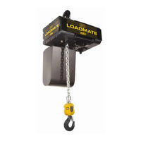
R&M LOADMATE LM 16 Manuals
Manuals and User Guides for R&M LOADMATE LM 16. We have
6
R&M LOADMATE LM 16 manuals available for free PDF download: Installation And Maintenance Manual, Installation & Maintenance Instructions Manual, Operator's Manual
R&M LOADMATE LM 16 Installation And Maintenance Manual (89 pages)
Brand:
R&M
| Category:
Chain Hoists
| Size: 3.37 MB
Table of Contents
Table of Contents
3
Introduction
5
Contact Information
5
Warranty
5
Disclaimer
5
Safety
6
Placards and Instructions
8
Installation
9
General
9
Lubrication
9
Mounting
10
Load Hook Throat Opening
10
Electrical Connection
11
Three Phase Power Connections
12
Single Phase Power Connections
13
Initial Start-Up
14
General
14
Correcting the Direction of Hook Travel
14
Operational Checks - no Load
15
Operational Checks - with Load
15
Hoist Operation
16
Low Headroom Trolley
17
Description - Technical Characteristics (Low Headroom Trolley)
17
Technical Characteristics
17
Environmental Data
18
Optional Equipment
18
Swivel Trolley
19
Description - Technical Characteristics (Swiveling Trolley to 3.2 Tons)
19
Technical Characteristics
19
Installation of Swivel Trolley
20
Electric Swivel Trolley
21
Swiveling Trolley (3.2 Tons)
22
Swiveling Trolley (3.2 to 5.0 Tons) (NOT LOCALLY AVAILABLE)
22
Procedure to Adjust Swivel Trolley Guide Rollers
23
Maintenance
24
Basic Hoist Construction
24
Motor / Body
24
Hoist Motor Brake and Load-Limiting Device
25
Slip Clutch Operation
25
Slip Clutch Adjustment after Installation
27
Hoist Motor Brake Adjustment (See Figure 11)
28
Replacement Criteria for Motor Brakes
29
Load Chain
30
General
30
Maintenance Inspection
30
Load Chain Specifications (See Figure 12)
32
Removing the Load Chain
32
Installing the Load Chain
33
Fall Stop Assembly
35
General
35
Removing Fall Stop (Figure 14)
35
Fall Stop Installation (Figure 14)
35
Chain Container
36
Removing Chain Container (Figure 15)
36
Installing Chain Container (Figure 15)
36
Vinyl Chain Bag (Optional)
37
Installing Vinyl Chain Bag (Figure 16)
37
Limit Switches
38
Upper and Lower Travel Safety Limit Switch
38
Upper and Lower Rotary Travel Limit Switch (Optional Only on 3-Phase Units)
39
Hooks
40
General
40
Inspection
41
Hook Dimensions and Specifications
41
Top Hook
42
Control Changes and Fuses
43
Control Circuit Fuses
43
Three-Phase Single-Speed Voltage Changes
44
Control Panel Layout - Three Phase - Two-Speed Hoist - 208/230/460 Volts
45
Three Phase - Wiring Diagram - Two-Speed Hoist - 208/230/460 Volts - Power Circuit
46
Three Phase - Wiring Diagram - Two-Speed Hoist - 208/230/460 Volts - Control Circuit
47
Control Panel Layout - Three Phase - Two-Speed Hoist - 575 Volts
48
Three Phase - Wiring Diagram - Two-Speed Hoist - 575 Volts - Power Circuit
49
Three Phase - Wiring Diagram - Two-Speed Hoist - 575 Volts - Control Circuit
50
Control Panel Layout - Three Phase - Single Speed Hoist - 208/230 Volts
51
Control Panel Layout - Three Phase - Single Speed Hoist - 460 Volts
52
Three Phase - Wiring Diagram - Single Speed Hoist - 208/230/460 Volts - Power Circuit
53
Three Phase - Wiring Diagram - Single Speed Hoist - 208/230/460 Volts - Control Circuit
54
Power Supply Layout - Single Phase - Control Panel - 115V
55
Single Phase - Wiring Diagram - 115V Power Circuit
56
Single Phase - Wiring Diagram - Control Circuit
57
Wiring Diagram - Single Phase - 3 Button - Push Button
58
Wiring Diagram - 5 Button - Push Button
59
Wiring Diagram - 7 Button - Push Button
60
Preventative Maintenance
61
Maintenance and Inspection Table
61
Lubrication
62
Recommended Technical Support for Various Spare Parts
63
Screw Tightening Torque (Lb-Ft) Specifications
63
Troubleshooting
64
Parts Illustration
66
Hoist Body - Three Phase Power Supply
66
Hoist Body - Single Phase Power Supply
68
Helical Gear Mechanism & Brake
70
Lifting Assembly
72
Chain Guide Assembly - with Limit Switches
74
Controls
75
Rotary Limit Switch
76
Double Brake Mechanism
77
Low Headroom Trolley
78
Low Headroom Trolley (Drive Components)
78
Low Headroom Trolley (Suspension Components)
80
Electric Trolley (Swiveling Trolley 0 to 3.2 Tons (3200 Kg))
82
Push Button Assembly - Horizontal Pairs of Buttons
84
Pushbutton Assembly - Horizontal Pairs of Buttons
85
Push Button Assembly - Vertical Pairs of Buttons (Option)
86
Push Button Assembly - Vertical Buttons (Option)
88
Advertisement
R&M LOADMATE LM 16 Installation And Maintenance Manual (85 pages)
Brand:
R&M
| Category:
Chain Hoists
| Size: 2.38 MB
Table of Contents
Table of Contents
3
1 Introduction
5
Contact Information
5
Warranty
5
Disclaimer
5
Safety
6
Placards and Instructions
8
2 Installation
9
General
9
Lubrication
9
Mounting
10
Load Hook Throat Opening
10
Electrical Connection
11
Three Phase Power Connections
12
3 Initial Start-Up
13
General
13
Correcting the Direction of Hook Travel
13
Operational Checks - no Load
14
Operational Checks - with Load
14
4 Hoist Operation
15
5 Low Headroom Trolley
16
Description - Technical Characteristics (Low Headroom Trolley)
16
Technical Characteristics
16
Environmental Data
17
Optional Equipment
17
6 Swivel Trolley
18
Description - Technical Characteristics (Swiveling Trolley to 3.2 Tons)
18
Technical Characteristics
18
Installation of Swivel Trolley
19
Electric Swivel Trolley
20
Swiveling Trolley (3.2 Tons)
21
Swiveling Trolley (3.2 to 5.0 Tons) (NOT LOCALLY AVAILABLE)
21
Procedure to Adjust Swivel Trolley Guide Rollers
22
7 Maintenance
23
Basic Hoist Construction
23
Motor / Body
23
Hoist Motor Brake and Load-Limiting Device
24
Slip Clutch Adjustment
24
Slip Clutch Adjustment after Installation
25
Hoist Motor Brake Adjustment
26
Replacement Criteria for Motor Brakes
27
Load Chain
28
General
28
Maintenance Inspection
28
Load Chain Specifications (See Figure 13)
30
Removing the Load Chain
30
Installing the Load Chain
31
Fall Stop Assembly
33
General
33
Removing Fall Stop (Figure 16)
33
Fall Stop Installation (Figure 16)
33
Chain Container
34
Removing Chain Container (Figure 17)
34
Installing Chain Container (Figure 17)
34
Vinyl Chain Bag (Optional)
35
Installing Vinyl Chain Bag (Figure 18)
35
Limit Switches
36
Upper and Lower Travel Safety Limit Switch
36
Upper and Lower Rotary Travel Limit Switch (Optional Only on 3-Phase Units)
37
Hooks
38
General
38
Hook Inspection
39
Top Hook
40
Control Changes and Fuses
41
Single-Speed solo Hoist - 208 Volt Wiring Diagram
43
Single-Speed solo Hoist - 230 Volt Wiring Diagram
44
Single-Speed solo Hoist - 460 Volt Wiring Diagram
45
Two-Speed solo Hoist - 208 Volt Wiring Diagram
46
Two-Speed solo Hoist - 230 Volt Wiring Diagram
47
Two-Speed solo Hoist - 460 Volt Wiring Diagram
48
Two-Speed solo Hoist - 575 Volt Wiring Diagram
49
Single-Speed Hoist - Modular Crane - 208 Volt Diagram
50
Single-Speed Hoist - Modular Crane - 230 Volt Diagram
51
Single-Speed Hoist - Modular Crane - 460 Volt Diagram
52
Two-Speed Hoist - Modular Crane - 208 Volt Diagram
53
Two-Speed Hoist - Modular Crane - 230 Volt Diagram
54
Two-Speed Hoist - Modular Crane - 460 Volt Diagram
55
Two-Speed Hoist - Modular Crane - 575 Volt Diagram
56
Wiring Diagram - 3 Button - Push Button
57
Wiring Diagram - 5 Button - Push Button
58
Wiring Diagram - 7 Button - Push Button
59
8 Preventative Maintenance
60
Maintenance and Inspection Table
60
Lubrication
61
Recommended Technical Support for Various Spare Parts
62
Screw Tightening Torque (Lb-Ft) Specifications
62
Troubleshooting
63
9 Parts Illustration
64
Hoist Body
64
Gear Mechanism with Motor Brake
66
Lifting Assembly
68
Controls
70
Upper and Lower Limit Switch
72
Double Brake Mechanism
73
Low Headroom Trolley
74
Low Headroom Trolley (Drive Components)
74
Low Headroom Trolley (Suspension Components)
76
Electric Trolley (Swiveling Trolley 0 to 3.2 Tons (3200 Kg))
78
Push Button Assembly - Horizontal Pairs of Buttons
80
Push Button Assembly - Horizontal Pairs of Buttons
81
Push Button Assembly - Vertical Pairs of Buttons (Option)
82
Push Button Assembly - Vertical Buttons (Option)
84
R&M LOADMATE LM 16 Installation And Maintenance Manual (73 pages)
Brand:
R&M
| Category:
Chain Hoists
| Size: 2.24 MB
Table of Contents
Table of Contents
3
1 Introduction
5
Contact Information
5
Warranty
5
Disclaimer
5
Safety
6
Placards and Instructions
8
2 Installation
9
General
9
Chain Container Installation
9
Lubrication
9
Mounting
10
Load Hook Throat Opening
10
Electrical Connection
11
Three Phase Power Connections
12
3 Initial Start-Up
13
General
13
Correcting the Direction of Hook Travel
13
Operational Checks - no Load
14
Operational Checks - with Load
14
4 Hoist Operation
15
5 Swivel Trolley
16
Description - Technical Characteristics (Swiveling Trolley to 3.2 Tons)
16
Technical Characteristics
16
Installation of Swivel Trolley
17
Electric Swivel Trolley
18
Swiveling Trolley (3.2 Tons)
19
Swiveling Trolley (3.2 to 5.0 Tons) (NOT LOCALLY AVAILABLE)
19
Procedure to Adjust Swivel Trolley Guide Rollers
20
6 Maintenance
21
Basic Hoist Construction
21
Hoist Motor and Brake Assembly
22
Replacement Criteria for Motor Brakes
25
Torque Limiter (Refer to Figure 11)
27
Load Chain
28
Maintenance Inspection
28
Load Chain Specifications (See Figure 12)
30
Removing the Load Chain
30
Installing the Load Chain
31
Fall Stop Assembly (Refer to Figure 14)
33
Chain Container
34
Upper and Lower Travel Safety Limit Switch
35
Upper and Lower Rotary Travel Limit Switch
36
Hooks
37
Hook Inspection
38
Hook Dimensions
39
Top Hook
40
Controls
41
Two Speed - Three Phase - 208 / 230 / 460 Volt - Power Circuit
43
Two Speed - Three Phase - 208 / 230 / 460 Volt - Control Circuit
44
Two Speed - Three Phase - 575 Volt - Power Circuit
45
Two Speed - Three Phase - 575 Volt - Control Circuit
46
Wiring Diagram - 3 Button - Push Button
47
Wiring Diagram - 5 Button - Push Button
48
Wiring Diagram - 7 Button - Push Button
49
7 Preventative Maintenance
50
Maintenance and Inspection Table
50
Lubrication
51
Recommended Technical Support for Various Spare Parts
52
Screw Tightening Torque (Lb-Ft) Specifications
52
Troubleshooting
53
8 Parts Illustrations
54
Hoist Gearbox Components
54
C16 / C20 / C25 Hoist Motor & Brake Assembly
56
Lifting Assembly - C16 Only
58
Lifting Assembly - C20/25 Only
60
C16 / C20 / C25 Electrical Control Assembly
62
Double Brake (Option) C16 / C20 / C25
64
Electric Trolley (Swiveling Trolley 0 to 3.2 Tons (3200 Kg))
66
Push Button Assembly - Horizontal Pairs of Buttons
68
Push Button Assembly - Horizontal Pairs of Buttons
69
Push Button Assembly - Vertical Pairs of Buttons (Option)
70
Push Button Assembly - Vertical Buttons (Option)
72
Advertisement
R&M LOADMATE LM 16 Installation And Maintenance Manual (65 pages)
Brand:
R&M
| Category:
Chain Hoists
| Size: 1.25 MB
Table of Contents
Table of Contents
3
1 Introduction
5
Contact Information
5
Warranty
5
Disclaimer
5
Safety
6
Placards and Instructions
8
2 Installation
9
General
9
Lubrication
9
Mounting
10
Load Hook Throat Opening
10
Electrical Connection
11
Three Phase Power Connections
12
Single Phase Power Connections
13
3 Initial Start-Up
14
General
14
Correcting the Direction of Hook Travel
14
Operational Checks - no Load
15
Operational Checks - with Load
15
4 Hoist Operation
16
5 Maintenance
17
Basic Hoist Construction
17
Motor / Body
17
Hoist Motor Brake and Load-Limiting Device
18
Slip Clutch Operation (See Figure 5)
18
Slip Clutch Adjustment after Installation
20
Hoist Motor Brake Adjustment (See Figure 5)
21
Replacement Criteria for Motor Brakes
22
Load Chain
23
General
23
Maintenance Inspection
23
Load Chain Specifications (See Figure 6)
25
Removing the Load Chain
25
Installing the Load Chain
26
Fall Stop Assembly
28
General
28
Fall Stop Installation
28
Chain Container
29
Limit Switches
30
Upper and Lower Travel Safety Limit Switch
30
Upper and Lower Rotary Travel Limit Switch (Optional Only on 3-Phase Units)
31
Hooks
32
General
32
Inspection
33
Hook Dimensions and Specifications
33
Top Hook
34
Controls
35
General
35
Control Fuses
35
Control Panel Layout - Three Phase - Two Speed
36
Control Panel Layout - Single Phase - Single Speed - 115 Volt
37
Wiring Diagrams
38
Wiring Diagram - Three Phase - Two-Speed Hoist
38
Wiring Diagram - Single Phase - Connections and Components
39
Wiring Diagram - Single Phase - Power Circuit
40
Wiring Diagram - Single Phase - Control Circuit
41
Wiring Diagram - 3 Button - Push Button
42
Wiring Diagram - 5 Button - Push Button
43
Wiring Diagram - 7 Button - Push Button
44
6 Preventative Maintenance
45
Maintenance and Inspection Table
45
Lubrication
46
Recommended Technical Support for Various Spare Parts
47
Screw Tightening Torque (Lb-Ft) Specifications
47
Troubleshooting
48
7 Parts Illustration
50
Hoist Body
50
Helical Gear Mechanism & Brake
52
Lifting Assembly
54
Control Panel Assembly - 3 Phase Power Supply
56
Control Panel Assembly - 115 Volt 1-Phase Power Supply
57
Gear Limit Switch (OPTION)
58
Push Button Assembly - Horizontal Pairs of Buttons
59
Push Button Assembly - Horizontal Pairs of Buttons
60
Push Button Assembly - Vertical Pairs of Buttons (Option)
62
Push Button Assembly - Vertical Buttons (Option)
64
R&M LOADMATE LM 16 Installation & Maintenance Instructions Manual (58 pages)
ELECTRIC CHAIN HOIST
Brand:
R&M
| Category:
Chain Hoists
| Size: 1.68 MB
Table of Contents
Table of Contents
3
1 Introduction
5
Contact Information
5
Warranty
5
Disclaimer
5
Safety
6
Placards and Instructions
8
2 Installation
9
General
9
Chain Container Installation
9
Lubrication
9
Mounting
10
Load Hook Throat Opening
10
Electrical Connection
10
Three Phase Power Connections
11
3 Initial Start-Up
12
General
12
Correcting the Direction of Hook Travel
12
Operational Checks - no Load
12
Operational Checks - with Load
13
4 Hoist Operation
14
5 Maintenance
16
Construction
16
Hoist Motor and Brake Assembly
17
Torque Limiter (Refer to Figure 5.4)
21
Load Chain
22
Maintenance Inspection
22
Load Chain Specifications (See Figure 5.5)
24
Removing the Load Chain
24
Installing the Load Chain
25
Fall Stop Assembly (Refer to Figure 5.8)
26
Chain Container
27
Upper and Lower Travel Safety Limit Switch
28
Upper and Lower Rotary Travel Limit Switch
28
Hooks
29
Hook Inspection
29
Hook Dimensions
30
Top Hook
31
Controls
32
Two Speed - Three Phase - 208 / 230 / 460 Volt - Power Circuit
34
Two Speed - Three Phase - 208 / 230 / 460 Volt - Control Circuit
35
Two Speed - Three Phase - 208 / 230 / 460 Volt - Push Button
36
Two Speed - Three Phase - 575 Volt - Power Circuit
37
Two Speed - Three Phase - 575 Volt - Control Circuit
38
Two Speed - Three Phase - 575 Volt - Push Button
39
6 Preventative Maintenance
41
Maintenance and Inspection Table
41
Lubrication
42
Recommended Technical Support for Various Spare Parts
43
Screw Tightening Torque (Lb-Ft) Specification
43
Troubleshooting
44
7 Parts Illustrations
45
Basic Hoist Assembly
45
Hoist Gearbox Components
47
C16 / C20 / C25 Hoist Motor & Brake Assembly
49
Lifting Assembly - C16 Only
51
Lifting Assembly - C20/25 Only
53
C16 / C20 / C25 Electrical Control Assembly
55
Push Button Assembly -Vertical Pairs of Buttons
57
R&M LOADMATE LM 16 Operator's Manual (42 pages)
ELECTRIC CHAIN HOIST
Brand:
R&M
| Category:
Chain Hoists
| Size: 0.79 MB
Table of Contents
Table of Contents
3
1 Introduction
4
Contact Information
4
Disclaimer of Warranty
4
Disclaimer of Liability
4
Indemnity
5
2 Scope and Purpose
6
Scope
6
Purpose
6
Installation and Maintenance Manual
6
3 Safety
7
Training Requirements
7
Introduction to Safety
8
Owner / User / Operator Responsibilities
9
Recommended Operator Qualifications
11
4 Electric Chain Hoist Construction
12
General Hoist Construction
12
Lifting Medium
12
Power for Operation
12
Suspension Types
13
Directional Travel of Overhead Hoists
15
Principal Parts of an Electric Chain Hoist
17
5 Safe Operating Practices
25
Before each Shift or the First Time the Hoist Is Used each Shift
25
Before Operating a Hoist and Applying a Load
28
Moving the Load
30
Parking the Load
31
Hoist Limit Devices
32
General Recommendations
32
Recommended General Do Not's
33
Operator Hand Signals
34
6 Appendix - a - Definitions of Electric Chain Hoist Terms
35
7 Appendix - B - References
38
8 Appendix - C - Recommended Practices - Electric Powered Hoists
40
Advertisement
Related Products
R&M LOADMATE LM Series
R&M LOADMATE LM1
R&M LOADMATE LM 01
R&M LOADMATE LM 05
R&M LOADMATE LM 10
R&M LOADMATE LM 20
R&M LOADMATE LM 25
R&M LM
R&M LOADMATE LM05 II Series
R&M LK10C022200
R&M Categories
Chain Hoists
Industrial Equipment
Enclosure
Adapter
Media Converter
More R&M Manuals
Login
Sign In
OR
Sign in with Facebook
Sign in with Google
Upload manual
Upload from disk
Upload from URL