Sign In
Upload
Manuals
Brands
R&M Manuals
Chain Hoists
LOADMATE LM05 II Series
R&M LOADMATE LM05 II Series Manuals
Manuals and User Guides for R&M LOADMATE LM05 II Series. We have
1
R&M LOADMATE LM05 II Series manual available for free PDF download: Installation And Maintenance Manual
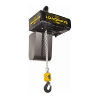
R&M LOADMATE LM05 II Series Installation And Maintenance Manual (89 pages)
Brand:
R&M
| Category:
Chain Hoists
| Size: 3.37 MB
Table of Contents
Table of Contents
3
Introduction
5
Contact Information
5
Warranty
5
Disclaimer
5
Safety
6
Placards and Instructions
8
Installation
9
General
9
Lubrication
9
Mounting
10
Load Hook Throat Opening
10
Electrical Connection
11
Three Phase Power Connections
12
Single Phase Power Connections
13
Initial Start-Up
14
General
14
Correcting the Direction of Hook Travel
14
Operational Checks - no Load
15
Operational Checks - with Load
15
Hoist Operation
16
Low Headroom Trolley
17
Description - Technical Characteristics (Low Headroom Trolley)
17
Technical Characteristics
17
Environmental Data
18
Optional Equipment
18
Swivel Trolley
19
Description - Technical Characteristics (Swiveling Trolley to 3.2 Tons)
19
Technical Characteristics
19
Installation of Swivel Trolley
20
Electric Swivel Trolley
21
Swiveling Trolley (3.2 Tons)
22
Swiveling Trolley (3.2 to 5.0 Tons) (NOT LOCALLY AVAILABLE)
22
Procedure to Adjust Swivel Trolley Guide Rollers
23
Maintenance
24
Basic Hoist Construction
24
Motor / Body
24
Hoist Motor Brake and Load-Limiting Device
25
Slip Clutch Operation
25
Slip Clutch Adjustment after Installation
27
Hoist Motor Brake Adjustment (See Figure 11)
28
Replacement Criteria for Motor Brakes
29
Load Chain
30
General
30
Maintenance Inspection
30
Load Chain Specifications (See Figure 12)
32
Removing the Load Chain
32
Installing the Load Chain
33
Fall Stop Assembly
35
General
35
Removing Fall Stop (Figure 14)
35
Fall Stop Installation (Figure 14)
35
Chain Container
36
Removing Chain Container (Figure 15)
36
Installing Chain Container (Figure 15)
36
Vinyl Chain Bag (Optional)
37
Installing Vinyl Chain Bag (Figure 16)
37
Limit Switches
38
Upper and Lower Travel Safety Limit Switch
38
Upper and Lower Rotary Travel Limit Switch (Optional Only on 3-Phase Units)
39
Hooks
40
General
40
Inspection
41
Hook Dimensions and Specifications
41
Top Hook
42
Control Changes and Fuses
43
Control Circuit Fuses
43
Three-Phase Single-Speed Voltage Changes
44
Control Panel Layout - Three Phase - Two-Speed Hoist - 208/230/460 Volts
45
Three Phase - Wiring Diagram - Two-Speed Hoist - 208/230/460 Volts - Power Circuit
46
Three Phase - Wiring Diagram - Two-Speed Hoist - 208/230/460 Volts - Control Circuit
47
Control Panel Layout - Three Phase - Two-Speed Hoist - 575 Volts
48
Three Phase - Wiring Diagram - Two-Speed Hoist - 575 Volts - Power Circuit
49
Three Phase - Wiring Diagram - Two-Speed Hoist - 575 Volts - Control Circuit
50
Control Panel Layout - Three Phase - Single Speed Hoist - 208/230 Volts
51
Control Panel Layout - Three Phase - Single Speed Hoist - 460 Volts
52
Three Phase - Wiring Diagram - Single Speed Hoist - 208/230/460 Volts - Power Circuit
53
Three Phase - Wiring Diagram - Single Speed Hoist - 208/230/460 Volts - Control Circuit
54
Power Supply Layout - Single Phase - Control Panel - 115V
55
Single Phase - Wiring Diagram - 115V Power Circuit
56
Single Phase - Wiring Diagram - Control Circuit
57
Wiring Diagram - Single Phase - 3 Button - Push Button
58
Wiring Diagram - 5 Button - Push Button
59
Wiring Diagram - 7 Button - Push Button
60
Preventative Maintenance
61
Maintenance and Inspection Table
61
Lubrication
62
Recommended Technical Support for Various Spare Parts
63
Screw Tightening Torque (Lb-Ft) Specifications
63
Troubleshooting
64
Parts Illustration
66
Hoist Body - Three Phase Power Supply
66
Hoist Body - Single Phase Power Supply
68
Helical Gear Mechanism & Brake
70
Lifting Assembly
72
Chain Guide Assembly - with Limit Switches
74
Controls
75
Rotary Limit Switch
76
Double Brake Mechanism
77
Low Headroom Trolley
78
Low Headroom Trolley (Drive Components)
78
Low Headroom Trolley (Suspension Components)
80
Electric Trolley (Swiveling Trolley 0 to 3.2 Tons (3200 Kg))
82
Push Button Assembly - Horizontal Pairs of Buttons
84
Pushbutton Assembly - Horizontal Pairs of Buttons
85
Push Button Assembly - Vertical Pairs of Buttons (Option)
86
Push Button Assembly - Vertical Buttons (Option)
88
Advertisement
Advertisement
Related Products
R&M LOADMATE LM 01
R&M LOADMATE LM 05
R&M LOADMATE LM Series
R&M LOADMATE LM1
R&M LOADMATE LM 10
R&M LOADMATE LM 16
R&M LOADMATE LM 20
R&M LOADMATE LM 25
R&M LM
R&M LK10C022200
R&M Categories
Chain Hoists
Industrial Equipment
Enclosure
Adapter
Media Converter
More R&M Manuals
Login
Sign In
OR
Sign in with Facebook
Sign in with Google
Upload manual
Upload from disk
Upload from URL