Sign In
Upload
Manuals
Brands
INVT Manuals
Inverter
Goodrive 35 Series
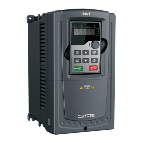
INVT Goodrive 35 Series Control Inverter Manuals
Manuals and User Guides for INVT Goodrive 35 Series Control Inverter. We have
2
INVT Goodrive 35 Series Control Inverter manuals available for free PDF download: Operation Manual
INVT Goodrive 35 Series Operation Manual (344 pages)
Close Loop Vector Control Inverter
Brand:
INVT
| Category:
Inverter
| Size: 11 MB
Table of Contents
Preface
2
Table of Contents
3
Content
3
Safety Precautions 1
6
What this Chapter Contains
6
Safety Definition
6
Warning Symbols
6
Safety Guidelines
7
Quick Start-Up 2
11
What this Chapter Contains
11
Unpacking Inspection
11
Application Confirmation
11
Environment
12
Installation Confirmation
12
Basic Commission
13
Product Overview 3
14
What this Chapter Contains
14
Basic Principles
14
Product Specification
15
Name Plate
18
Type Designation Key
18
Rated Specifications
19
I/O PG Card Selection
21
Structure Diagram
22
Installation Guidelines 4
24
What this Chapter Contains
24
Mechanical Installation
24
Standard Wiring
30
Standard Wiring (Control Circuit)
36
Layout Protection
46
Keypad Operation Procedure 5
48
What this Chapter Contains
48
Keypad
48
Keypad Displaying
51
Keypad Operation
52
Function Parameters 6
55
What this Chapter Contains
55
Goodrive35 General Series Function Parameters
55
Basic Operation Instruction 7
173
What this Chapter Contains
173
First Powering on
173
Vector Control
178
SVPWM Control
183
Torque Control
189
Parmeters of the Motor
192
Start-Up and Stop Control
197
Frequency Setting
202
Analog Input
206
Analog Output
208
Digital Input
212
Digital Input
222
Simple PLC
227
Multi-Step Speed Running
230
PID Control
232
Commissioning for Special Functions
236
Fault Solutions
244
Fault Tracking 8
248
What this Chapter Contains
248
Alarm and Fault Indications
248
How to Reset
248
Fault History
248
Fault Instruction and Solution
248
Common Fault Analysis
254
Maintenance and Hardware Diagnostics 9
260
What this Chapter Contains
260
Maintenance Intervals
260
Cooling Fan
263
Capacitors
264
Power Cable
266
Brief Instruction to Modbus Protocol
267
Communication Protocol 10
267
What this Chapter Contains
267
Application of the Inverter
268
RTU Command Code and Communication Data Illustration
274
Common Communication Fault
288
Appendix A
289
Extension Card
289
What this Chapter Contains
289
PROFIBUS/CANOPEN Extension Card
289
Canopen Optional Cards
307
Appendix B
308
Technical Data
308
What this Chapter Contains
308
Ratings
308
Grid Specifications
309
Motor Connection Data
309
Applicable Standards
310
EMC Regulations
311
Appendix C
313
Dimension Drawings
313
What this Chapter Contains
313
Keypad Structure
313
Inverter Structure
314
Dimensions for Inverters of AC 3PH 380V(-15%)~440V(+10%)
315
Dimensions for Inverters of AC 3PH 520V(-15%)~690V(+10%)
318
Appendix D
322
Peripheral Options and Parts
322
What this Chapter Contains
322
Peripherial Wiring
322
Power Supply
323
Cables
324
Breaker and Electromagnetic Contactor
329
Reactors
331
Filter
334
Braking System
337
Further Information
343
Advertisement
INVT Goodrive 35 Series Operation Manual (282 pages)
Close Loop Vector Control Inverter
Brand:
INVT
| Category:
Inverter
| Size: 11 MB
Table of Contents
Table of Contents
3
Chapter 1 Safety Precautions
8
What this Chapter Contains
8
Safety Definition
8
Warning Symbols
8
Safety Guidelines
9
Delivery and Installation
9
Commission and Running
10
Maintenance and Replacement of Components
11
Scrap Treatment
11
Chapter 2 Quick Start-Up
12
What this Chapter Contains
12
Unpacking Inspection
12
Application Confirmation
12
Environment
12
Installation Confirmation
13
Basic Commission
13
Chapter 3 Product Overview
14
What this Chapter Contains
14
Basic Principles
14
Product Specification
15
Name Plate
17
Type Designation Key
17
Model
18
Rated Values
18
Rated Value of AC 3PH 380 V (-15%) - 440 V (+10%)
18
Rated Value of AC 3PH 520 V (-15%) - 690 V (+10%)
19
Structure Diagram
20
Chapter 4 Installation Guidelines
21
What this Chapter Contains
21
Mechanical Installation
21
Installation Environment
21
Installation Direction
22
Installation Manner
22
Single Installation
23
Multiple Installations
23
Vertical Installation
24
Tilt Installation
25
Standard Wiring
25
Main Circuit Connection Diagram
25
Main Circuit Connection Diagram
26
Terminals Figure of Main Circuit
27
Wiring of Terminals in Main Circuit
31
Standard Wiring (Control Circuit)
32
Wiring Diagram of Basic Control Circuit
32
C1 Terminal (EC-PG301-24) Instruction and the Wiring Diagram
35
D1 Terminal (EC-PG304-05) Instruction and the Wiring Diagram
36
H1 Terminal (EC-PG305-12) Instruction and the Wiring Diagram
37
H2 Terminal (EC-PG305-05) Instruction and the Wiring Diagram
39
S1 Terminal (EC-PG302-05) Instruction
41
Input/Output Signal Connection Diagram
42
Wiring Protection
43
Protecting the Inverter and Input Power Cable in Short-Circuit Situations
43
Protecting the Motor and Motor Cable in Short-Circuit Situations
43
Protecting the Motor against Thermal Overload
43
Implementing a Bypass Connection
43
Chapter 5 Keypad Operation Procedure
44
What this Chapter Contains
44
Keypad
44
Keypad Displaying
46
Displayed State of Stopping Parameter
46
Displayed State of Running Parameters
46
Displayed State of Fault
46
Displayed State of Function Codes Editing
47
Keypad Operation
47
How to Modify the Function Codes of the Inverter
47
How to Set the Password of the Inverter
48
How to Watch the Inverter State through Function Codes
48
Chapter 6 Function Parameters
50
What this Chapter Contains
50
Goodrive35 General Series Function Parameters
50
Chapter 7 Basic Operation Instruction
134
What this Chapter Contains
134
First Powering on
134
Vector Control
138
SVPWM Control
142
Torque Control
147
Parameters of the Motor
149
Start-Up and Stop Control
154
Frequency Setting
158
Analog Input
162
Analog Output
164
Digital Input
167
Digital Input
174
Simple PLC
178
Multi-Step Speed Running
180
PID Control
182
General Steps of PID Parameters Setting
183
PID Inching
184
Commissioning for Special Functions
186
Commissioning Steps
188
Fault Solutions
194
Chapter 8 Fault Tracking
197
Other States
201
Common Fault Analysis
202
Overvoltage
203
Abnormal Heating of the Motor
204
Overheat of the Inverter
205
Overcurrent
206
Chapter 9 Maintenance and Hardware Diagnostics
207
Cooling Fan
209
Capacitors
210
Change Electrolytic Capacitors
211
Chapter 10 Communication Protocol
212
RTU Mode
215
RTU Command Code and Communication Data Illustration
217
Command Code: 06H
219
Command Code 08H for Diagnosis
220
Command Code: 10H
221
Fieldbus Ratio Values
225
Fault Message Response
226
Example of Writing and Reading
228
Common Communication Fault
232
Appendix A Extension Card
233
A.2.2 EC-TX-103 Communication Card
234
A.2.4 Compatible Motor of EC-TX-103 Communication Card
235
A.2.7 System Configuration
239
A.2.8 PROFIBUS-DP Communication
240
A.2.9 Fault Information
248
A.3 Canopen Optional Cards
249
Appendix B Technical Data
250
B.3 Grid Specifications
251
B.5 Applicable Standards
252
B.6.1 Category C2
253
Appendix C Dimension Drawings
254
C.3 Inverter Structure
255
C.4 Dimensions for Inverters of AC 3PH 380 V (-15%) – 440 V (+10%)
256
C.4.2 Flange Installation
257
C.4.3 Floor Installation
259
C.5.2 Flange Installation
261
C.5.3 Floor Installation
262
Appendix D Peripheral Options and Parts
263
D.3 Power Supply
264
D.4.2 Control Cables
265
D.4.3 Routing the Cables
269
D.5 Breaker and Electromagnetic Contactor
270
D.5.2 the Inverters of AC 3PH 520 V (-15%) – 690 V (+10%)
271
D.6.1 Ac 3Ph 380 V (-15%) – 440 V (+10%)
272
D.6.2 Ac 3Ph 520 V (-15%) – 690 V (+10%)
273
D.7.1 Filter Type Instruction
274
D.7.2 Ac 3Ph 380 V (-15%) – 440 V (+10%)
275
D.8 Brake System
276
D.8.2 Selecting the Brake Resistor Cables
279
Appendix E Further Information
281
Advertisement
Related Products
INVT Goodrive 300
INVT Goodrive 300-16
INVT Goodrive 800 Series
INVT Goodrive 310-UL Series
INVT 315G/355P-4
INVT 355G/400P-4
INVT 11020-00136
INVT 11020-00137
INVT 11020-00138
INVT 11020-00139
INVT Categories
Inverter
DC Drives
Servo Drives
Controller
UPS
More INVT Manuals
Login
Sign In
OR
Sign in with Facebook
Sign in with Google
Upload manual
Upload from disk
Upload from URL