Sign In
Upload
Manuals
Brands
Intel Manuals
Server
SERVER SYSTEM SR2500AL
Intel SERVER SYSTEM SR2500AL Manuals
Manuals and User Guides for Intel SERVER SYSTEM SR2500AL. We have
3
Intel SERVER SYSTEM SR2500AL manuals available for free PDF download: User Manual, Manual, Specification
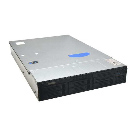
Intel SERVER SYSTEM SR2500AL User Manual (210 pages)
Intel Server User Manual
Brand:
Intel
| Category:
Server
| Size: 5.66 MB
Table of Contents
Safety Information
3
Important Safety Instructions
3
Wichtige Sicherheitshinweise
3
Consignes de Sécurité
3
Instrucciones de Seguridad Importantes
3
Preface
7
About this Manual
7
Manual Organization
7
Product Contents
8
Intel ® Server System SR2500ALLX/SR2500ALLXR Contents
8
Table of Contents
11
Chapter 1: Server System References
23
Table 1. Server System References
23
Chapter 2: Server System Features
25
Figure 1. Intel ® Integrated Server System SR2500AL
25
Table 2. Intel ® Server System SR2500ALLX And/Or the Intel ® Server System SR2500ALBRP Feature Summary
26
Chassis Component Identification
28
Internal Components
28
Figure 2. Chassiscomponents
28
Server Board Connector and Component Locations
29
Figure 3. Server Board Connector and Component Locations
30
Configuration Jumpers
31
Figure 4. BIOS Select Jumper
31
Figure 5. Recovery Jumpers
32
Figure 6. Light Guided Diagnostic Leds
33
Figure 7. Back Panel Connectors
34
RAID Support
35
Table 3. NIC LED Descriptions
35
Figure 8. Passive MID-Plane Components
36
Figure 9. Active SAS/SATA MID-Plane Components
37
Figure 10. Hot-Swap SAS/SATA Backplane Components (Front View)
38
Figure 11. Hot-Swap SAS/SATA Backplane Components (Rear View)
39
Standard Control Panel
40
Figure 12. Standard Control Panel
41
Intel ® Local Control Panel
41
Bezels
42
Figure 13. Intel ® Local Control Panel
42
Figure 14. Server System Back
43
Peripheral Devices
44
Hard Disk Drives
44
Figure 15. Optional Peripherals
44
Slimline Optical Drive Carrier
45
Advanced Management Options
45
Intel® Remote Management Module
45
Rack-Mounted Systems
45
Chapter 3: Hardware Installations and Upgrades
47
Before You Begin
47
Tools and Supplies Needed
47
System References
47
Removing and Installing from a Rack
47
Fixed Bracket Rack Mount Removal
47
Fixed Bracket Rack Mount Installation
48
Basic Rail Rack Mount Removal
49
Basic Rail Rack Mount Installation
49
Tool-Less Rail Rack Mount Servicing
50
Removing and Installing the Front Bezel
50
Figure 16. Front Bezel Supporting the Standard Control Panel
50
Figure 17. Front Bezel Supporting the Intel ® Local Control Panel
50
Removing the Front Bezel
51
Figure 18. Removing the Front Bezel
51
Installing the Front Bezel
52
Removing and Installing the System Cover
52
Removing the System Cover
52
Figure 19. Installing the Front Bezel
52
Installing the Server System Cover
53
Figure 20. Removing the Server System Cover
53
Removing and Installing the Processor Air Duct
54
Removing the Processor Air Duct
54
Figure 21. Installing the Server System Cover
54
Figure 22. Removing the Processor Air Duct
55
Installing the Processor Air Duct
56
Figure 23. Removing the Processor 2 Air Dam (Optional - Only if Two Processors Are Installed)
56
Installing and Removing Memory
57
Installing Dimms
57
Figure 24. Installing the Processor Air Duct
57
Figure 25. Installing the Memory
58
Removing Dimms
59
Installing the Processor
59
Figure 26. Lifting the Processor Socket Handle
60
Figure 27. Installing the Processor
60
Installing the Heat Sink(S)
61
Figure 28. Removing the Socket Cover
61
Figure 29. Installing the Heat Sink (2U Passive Heat Sink Shown)
61
Removing a Processor
62
Removing and Installing the Small Air Baffle
62
Removing the Small Air Baffle
63
Installing the Small Air Baffle
63
Figure 30. Removing the Small Air Baffle
63
Removing and Installing the Large Air Baffle
64
Removing the Large Air Baffle
64
Figure 31. Installing the Small Air Baffle
64
Installing the Large Air Baffle
65
Figure 32. Removing the Large Air Baffle
65
Installing and Removing a Hot-Swap Hard Drive
66
Installing a SAS or SATA Hot-Swap Hard Disk Drive
66
Figure 33. Installing the Large Air Baffle
66
Figure 34. Removing Hot-Swap Disk Carrier from the Server System
67
Figure 35. Removing Retention Device from Drive Carrier
67
Figure 36. Installing Hard Drive into Carrier
68
Figure 37. Install Drive Assembly into the Server System
68
Removing a SAS or SATA Hot-Swap Hard Disk Drive
69
Installing or Removing a Slimline Optical Drive or Internal USB Floppy
69
Installing a Slimline Optical Drive or Internal USB Floppy
70
Figure 38. Installing an Optical Drive into the Drive Tray
70
Removing a Slimline Optical Drive or Internal USB Floppy
71
Figure 39. Installing an Optical Drive Assembly into the Server System
71
Figure 40. Removing the Slimline Optical Drive Assembly from the Server System
72
Figure 41. Removing the Slimline Optical Drive from the Tray
72
Installing a Tape Drive
73
Figure 42. Installing Filler Blank into the Server System
73
Figure 43. Removing Tape Drive Filler Panel from the Server System
74
Figure 44. Removing Sixth Drive Filler Panel from the Server System
74
Figure 45. Inserting a Tape Drive into the Carrier
75
Figure 46. Installing Tape Drive Assembly into the Server System
75
Installing a Sixth Hard Drive
76
Figure 47. Installing Sixth HDD Bracket
76
Figure 48. Installing Power and SATA Cables (Active MID-Plane Installed)
77
Figure 49. Installing Power and SATA Cables (Passive MID-Plane Installed)
78
Filling Empty Server System Bays
79
Installing and Removing the PCI Riser Assembly
79
Removing the PCI Riser Assembly
79
Figure 50. Installing the Filler Panels
79
Figure 51. Removing PCI Riser Assembly from the Server System
80
Installing the PCI Riser Assembly
81
Figure 52. Installing PCI Riser Assembly into the Server System
81
Replacing a PCI Riser Card
82
Removing a PCI Riser Card
82
Figure 53. Removing the PCI Riser Card from the Server System (Full Height Side)
83
Installing a PCI Riser Card
84
Figure 54. Installing PCI Riser Card into the Server System
84
Installing and Removing a PCI Add-In Card
85
Installing a PCI Add-In Card
85
Removing a PCI Add-In Card
86
Figure 55. Installing a Full Height Add-In Card
86
Figure 56. Removing a Full Height Add-In Card
87
Installing the I/O Expansion Module(S)
88
Figure 57. Installing the I/O Expansion Module to the Server Board
88
Removing the I/O Expansion Module(S)
89
Figure 58. Removing the I/O Expansion Module(S) from the Server Board
89
Installing the Intel RMM and Intel RMM NIC
90
Figure 59. Installing the Intel ® RMM and the Intel ® RMM NIC Module to the Server System
91
Removing the Intel ® RMM and Intel ® RMM NIC
92
Replacing the MID-Plane Board
93
Removing the MID-Plane Board
93
Figure 61. Removing the Bridge Board from the Server System
93
Figure 62. Removing the MID-Plane from the Server System
94
Installing the MID-Plane Board
94
Figure 63. Installing the MID-Plane into the Server System
95
Figure 64. Installing the Bridge Board into the Server System
95
Replacing the Backplane
96
Removing the Backplane
96
Figure 65. Removing the Backplane from the Server System
97
Installing the Backplane
98
Figure 66. Installing the Backplane into the Server System
98
Installing and Removing the RAID Activation Key and the RAID Mini DIMM
99
Installing the RAID Activation Key and the RAID Mini DIMM
99
Figure 67. Installing the RAID Activation Key and the RAID Mini DIMM
99
Removing the RAID Activation Key and the RAID Mini DIMM
100
Figure 68. Removing the RAID Activation Key and the RAID Mini DIMM
100
Installing and Removing the RAID Battery Backup Unit (BBU)
101
Installing the RAID Battery Backup Unit
101
Figure 69. Installing the RAID Battery Backup Unit
101
Removing the RAID Battery Backup Unit
102
Figure 70. Removing the RAID Battery Backup Unit
102
Installing and Removing the Server Board
103
Installing the Server Board
103
Figure 71. Installing the Server Board
103
Removing the Server Board
104
Figure 72. Removing the Server Board
105
Replacing the Backup Battery
106
Figure 73. Replacing the Backup Battery
107
Replacing the Power Supply
108
Figure 74. Removing Power Supply Filler Panel from the Server System
108
Figure 75. Removing Power Supply Module from the Server System
109
Figure 76. Installing Power Supply Module into the Server System
109
Figure 77. Installing Power Supply Filler Panel into the Server System
109
Replacing the Power Distribution Module
110
Figure 78. Removing the Power Distribution Module
110
Replacing the Control Panel
111
Figure 79. Removing Standard Control Panel Module from the Server System
112
Figure 80. Installing Control Panel Module into the Server System
112
Replacing a Fan Module
113
Replacing a Redundant Fan Module
113
Figure 81. Removing the Redundant Fan Module
114
Figure 82. Installing the Redundant Fan Module
114
Replacing a Fixed Fan Module
115
Figure 83. Removing the Fixed Fan Module
116
Figure 84. Installing the Fixed Fan Module
116
Replacing a Redundant System Fan
117
Figure 85. Removing a Fan from the Redundant Fan Module
118
Figure 86. Installing a Fan into the Redundant Fan Module
118
Replacing a Fixed Fan
119
Figure 87. Removing a Fan from the Fixed Fan Module
119
Installing and Removing the Rack Handles
120
Installing the Rack Handles
120
Figure 88. Installing a Fan into the Fixed Fan Module
120
Removing the Rack Handles
121
Figure 89. Installing the Rack Handle
121
Figure 90. Removing the Rack Handle
122
Chapter 4: Server Utilities
123
Using the BIOS Setup Utility
123
Starting Setup
123
If You Cannot Access Setup
123
Setup Menus
123
Table 4. Setup Menu Key Use
124
Upgrading the BIOS
125
Preparing for the Upgrade
125
Upgrading the BIOS
126
Clearing the Password
126
Clearing the CMOS
127
Figure 91. Clear Password Jumper
127
Figure 92. Clear CMOS Jumper
128
Appendix A: Technical Reference
129
Cable Routing
129
Figure 93. Cable Routing
129
Fan Connections
130
Figure 94. Connecting the Non-Redundant Fan Power Cables to the Passive MID-Plane Board
130
Figure 95. Connecting the Redundant Fan Power Cables to the Active MID-Plane Board
130
750W Single Power Supply Input Voltages
131
750W Single Power Supply Output Voltages
131
Table 5. Power Supply Output Capability
131
System Environmental Specifications
132
Table 6. System Environmental Specifications
132
Appendix B: Troubleshooting
133
Resetting the System
133
Table 7. Resetting the System
133
Problems Following Initial System Installation
134
First Steps Checklist
134
Hardware Diagnostic Testing
134
Verifying Proper Operation of Key System Lights
135
Confirming Loading of the Operating System
135
Specific Problems and Corrective Actions
135
Power Light Does Not Light
136
No Characters Appear on Screen
136
Characters Are Distorted or Incorrect
137
System Cooling Fans Do Not Rotate Properly
137
Drive Activity Light Does Not Light
138
CD-ROM Drive or DVD-ROM Drive Activity Light Does Not Light
138
Cannot Connect to a Server
138
Problems with Network
139
System Boots When Installing PCI Card
140
Problems with Newly Installed Application Software
140
Problems with Application Software that Ran Correctly Earlier
140
Devices Are Not Recognized under Device Manager (Microsoft* Windows* Operating System)
141
Hard Drive(S) Are Not Recognized
141
Bootable CD-ROM Disk Is Not Detected
141
LED Information
142
BIOS POST Beep Codes
142
Table 8. LED Information
142
Table 9. POST Error Beep Codes
142
Table 10. Error Beep Codes Generated by Intel
143
Appendix C: Intel ® Server Issue Report Form
145
DIMM Configuration
146
Operating System Information
146
Hard Drive Information
147
Management Information
147
Complete Problem Description
148
Appendix D: LED Decoder
149
Table 11. POST Progress Code LED Example
149
Figure 96. Diagnostic LED Placement Diagram
150
Table 12. Diagnostic LED POST Code Decoder
150
Appendix E: Getting Help
155
World Wide Web
155
Telephone
155
Latin America
156
Appendix F: Regulatory and Compliance Information
159
Product Regulatory Compliance
159
Product Safety Compliance
159
Product Regulatory Compliance References
160
Table 13. Product Regulatory Compliance Markings
160
Electromagnetic Compatibility Notices
163
FCC Verification Statement (USA)
163
Industry Canada (ICES-003)
164
Europe (CE Declaration of Conformity)
164
VCCI (Japan)
164
BSMI (Taiwan)
164
Korean Compliance (RRL)
165
CNCA (CCC-China)
165
Product Ecology Compliance
165
Table 14. Product Ecology Compliance Markings
166
Table 15. Other Markings
168
Regulated Specified Components
169
End-Of-Life / Product Recycling
170
Appendix G: Warranty
171
Limited Warranty for Intel® Chassis Subassembly Products
171
Warranty Limitations and Exclusions
172
Limitations of Liability
172
How to Obtain Warranty Service
172
Telephone Support
173
Returning a Defective Product
173
Appendix H: Installation/Assembly Safety Instructions
175
English
175
Deutsch
177
Français
179
Español
181
Chinese
183
Italiano
184
Appendix I: Safety Information
187
English
187
Server Safety Information
187
Safety Warnings and Cautions
187
Intended Application Uses
188
Site Selection
188
Equipment Handling Practices
188
Power and Electrical Warnings
189
System Access Warnings
190
Rack Mount Warnings
190
Electrostatic Discharge (ESD)
191
Other Hazards
191
Deutsch
192
Sicherheitshinweise für den Server
192
Sicherheitshinweise und Vorsichtsmaßnahmen
192
Zielbenutzer der Anwendung
193
Standortauswahl
193
Handhabung von Geräten
193
Warnungen zu Netzspannung und Elektrizität
194
Warnhinweise für den Systemzugang
195
Warnhinweise für Racks
195
Elektrostatische Entladungen (ESD)
196
Andere Gefahren
196
Français
197
Consignes de Securite Sur Le Serveur
197
Séurité: Avertissements Et Mises en Garde
197
Domaines D'utilisation Prévus
198
Sélection D'un Emplacement
198
Pratiques de Manipulation de L'équipement
199
Alimentation Et Avertissements en Matiére D'électricité
199
Avertissements Sur Le Cordon D'alimentation
200
Avertissements Sur L'accés Au Systéme
200
Avertissements Sur Le Montage en Rack
201
Décharges Électrostatiques (ESD)
202
Autres Risques
202
Périphériques Laser
203
Español
203
Información de Seguridad del Servidor
203
Advertencias y Precauciones sobre Seguridad
203
Aplicaciones y Usos Previstos
204
Seleccién de la Ubicación
204
Manipulacién del Equipo
205
Advertencias de Alimentacién y Eléctricas
205
Advertencias sobre el Cable de Alimentación
205
Advertencias el Acceso al Sistema
206
Advertencias sobre el Montaje en Bastidor
207
Descarga Electrostática (ESD)
207
Otros Riesgos
208
Advertisement
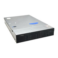
Intel SERVER SYSTEM SR2500AL Manual (110 pages)
Server Chassis/Server System
Brand:
Intel
| Category:
Server
| Size: 1.51 MB
Table of Contents
Table of Contents
4
1 Product Overview
13
Chassis Views
13
Figure 1. Front View with Optional Bezel
13
Figure 2. Front View Without Bezel (Shown with Standard Control Panel Option)
13
Figure 3. Back View - (Shown with 1+1 Power Supply Configuration)
13
Chassis Dimensions
14
System Components
14
Figure 4. Major Chassis Components
14
Table 1. Chassis Dimensions
14
System Boards
15
Figure 5. Back Panel Feature Overview
15
Control Panel Options
16
Figure 6. Control Panel Modules
16
Figure 7. Standard Control Panel Overview
17
Figure 8. LCD Control Panel Overview
18
Hard Drive and Peripheral Bays
19
Power Sub-System
19
Figure 9. Front Panel Feature Overview
19
System Cooling
20
Chassis Security
20
1.10 Rack and Cabinet Mounting Options
20
1.11 Front Bezel Features
21
Figure 10. Optional Front Bezel
21
Figure 11. Front Bezel Supporting Standard Control Panel
21
Figure 12. Front Bezel Supporting Intel Local Control Panel
22
2 Power Sub-System
23
Mechanical Overview
23
Single Power Supply Module Population
24
Handle and Retention Mechanism
24
Hot-Swap Support
24
Figure 14. Power Supply Blank
24
Airflow
25
AC Power Cord Specification Requirements
25
Output Cable Harness
25
Table 2. Power Harness Cable Definitions
25
P1 - Server Board Power Connector
26
P2 - Processor Power Connector
26
Table 3. P1 Main Power Connector
26
Table 4. P2 Processor Power Connector
26
P3 - Power Signal Connector
27
P4 - Backplane Power Connector
27
P5 MID-Plane Power Connector
27
AC Input Requirements
27
Table 5. P3 Power Signal Connector
27
Table 6. P4 Hot Swap Backplane Power Connector
27
Table 7. P5 MID-Plane Power Connector
27
AC Input Voltage Specification
28
AC Line 5 VSB Holdup
28
AC Line Dropout / Holdup
28
Efficiency
28
Table 8. Efficiency
28
Table 9. AC Input Rating
28
AC Inrush
29
Protection Circuits
29
Over-Current Protection (OCP)
29
Over-Voltage Protection (OVP)
29
Table 10. Over-Current Protection Limits / 240VA Protection
29
Over-Temperature Protection (OTP)
30
2.10 DC Output Specification
30
Output Power / Currents
30
Standby Output / Standby Mode
30
Table 11. Over-Voltage Protection (OVP) Limits
30
2.11 Power Supply Status LED
31
Table 12. LED Indicators
31
3 Cooling Sub-System
32
Non-Redundant Fan Module
33
Figure 15. Non-Redundant Fan Module
33
Table 13 Nonredundant Cooling Zones
33
Figure 16. Non-Redundant Fan Header Assignments on MID-Plane
34
Table 14. Non-Redundant Fan Connector Pin Assingment
34
Redundant System Fan Module
35
Figure 17. Fan Module Assembly
35
Table 15. Nonredundant Fan Header Assignment
35
Table 16 Redundant Cooling Zones
35
Figure 18. Redudant Fan Header Assignments on MID-Plane
36
Table 17 Redundant Fan Connector Pin Assingment
36
Air Flow Support
37
Power Supply Zone
37
Full Height Riser Zone
37
Table 18 Redundant Fan Header Assignment
37
CPU / Memory / Low Profile PCI Zone
38
Drive Bay Population
38
Figure 19. CPU Air Duct with Air Baffle
38
Figure 20. Drive Blank
38
4 Platform Control
39
Overview
39
5 System Board Interconnects
40
MID-Plane
40
Figure 21. Passive MID-Plane Board
40
Figure 22. SAS/SAS RAID MID-Plane Board
41
Table 19. 120-Pin Server Board-To-MID-Plane Bridge Board Connector Pin-Out
41
Table 20. MID-Plane Fan Header Pin-Outs
43
Table 21. MID-Plane Power Connector Pin-Out
43
Table 22. MID-Plane-To-Backplane Card Edge Connector #1 Pin-Out
44
Table 23. MID-Plane-To-Backplane Card Edge Connector #2 Pin-Out
45
Table 24. Active MID-Plane SAS RAID Battery Backup Connector Pin-Out
46
Table 25. Passive MID-Plane SATA/SAS Connector Pin-Outs
46
Figure 22. Active SAS/SAS RAID Midplane 2 Board
47
Bridge Board
48
Hot-Swap SATA/SAS Backplane
48
Figure 23. Bridge Board
48
Figure 24. Hot-Swap SAS/SATA Backplane (Front Side View)
49
Figure 25. Hot-Swap SAS/SATA Backplane (Back Side View)
49
Table 26. 2X4 SAS/SATA Backplane Power Connector Pin-Out (J7L2)
50
Table 27. 1X7 6Th HDD / Tape Drive Option Power Connector Pin-Out (J2M1)
50
Table 28. 6Th HDD Option SATA/SAS I/O Connector Pin-Out (J4L1)
50
Table 29. 2X22 Slim-Line IDE Optical Drive Connector Pin-Out (J5N1)
50
Table 30. Slim-Line Optical Drive Slot Connector (J1A1)
51
Table 31. IDE Device Master/Slave Configuration Jumper (J6L1)
51
Table 32. I2C Connector (J6L3)
52
Table 33. Pcie X4 Slot Connector from MID-Plane (J4N1)
52
Table 34. Pcie* X4 Slot Connector from MID-Plane (J6N1)
53
Table 35. USB Floppy Drive Connector (J2A1)
53
Table 36. Intel Local Control Panel (LCP) Connector (J9A1)
54
Table 37. Control Panel Slot Connector (J9B1)
54
Table 38. SAS/SATA Hard Drive Connector Pin-Outs (J2C3, J2B1, J4C1, J4B1, J7C1)
55
6 Peripheral and Hard Drive Sub-System
56
Slimline Drive Bay
56
Figure 27. Slim-Line Optical Drive Assembly
56
Figure 28. 50-Pin Connector to Slimline Optical Device
57
Table 39. J1L1 50-Pin Connector to Slimline Optical Device
57
Hard Drive Bays
58
Hot-Swap Drive Trays
58
Figure 29. Hard Drive Tray Assembly
58
Optional Tape Drive or 6 Th Hard Drive Flex Bay
59
Figure 26. Optional
59
Figure 31. Optional Tape Drive (Front View)
59
MID-Plane Options
60
Passive MID-Plane
60
Figure 32. Passive MID-Plane Board
60
Active MID-Plane with SAS /SAS RAID Support
61
Active Midplane2 with SAS/SAS RAID Support
61
Figure 33. Active MID-Plane with SAS / SAS RAID Support
61
Figure 34. Architecture Overview
63
Hot-Swap SAS/SATA Backplane
64
SAS/SATA Backplane Layout
65
SAS/SATA Backplane Functional Architecture
67
Table 40. Hard Drive LED Function Definitions
68
Table 41. Hard Drive Activity LED Functionality
68
7 Standard Control Panel
69
Control Panel Buttons
69
Control Panel LED Indicators
70
Table 42. Control Button and Intrusion Switch Functions
70
Table 43. Control Panel LED Functions
71
Power / Sleep LED
72
System Status LED
72
Table 44. SSI Power LED Operation
72
Table 45. Control Panel LED Operation
72
Drive Activity LED
73
System Identification LED
73
Control Panel Connectors
74
Table 46. External USB Connectors (J1B1)
74
Table 47. Video Connector (J1A1)
74
Internal Control Panel Interconnect
75
Table 48. 64-Pin Control Panel Connector (J6B1)
76
8 Intel Local Control Panel
77
LED Functionality
78
Table 49. Control Panel LED Functions
78
Power / Sleep LED
79
System Status LED
79
Table 50. SSI Power LED Operation
79
Table 51. Control Panel LED Operation
79
Drive Activity LED
80
System Identification LED
80
Intel ® Local Control Panel Interconnects
81
Table 52. 50-Pin Control Panel Connector
81
Table 53. Internal USB Header
82
9 PCI Riser Cards and Assembly
83
Riser Card Options
84
PCI Riser Card Mechanical Drawings
85
10 Supported Intel
89
Server Boards
89
Intel ® Server Board S5000PAL / S5000XAL Feature Set
89
Processor Support
91
11 Environmental and Regulatory Specifications
92
11.1 System Level Environmental Limits
92
11.2 Serviceability and Availability
92
Table 54. System Environmental Limits Summary
92
11.3 Replacing the Back up Battery
93
11.4 Product Regulatory Compliance
94
11.5 Use of Specified Regulated Components
94
Table 55. Product Safety & Electromagnetic (EMC) Compliance
95
11.6 Electromagnetic Compatibility Notices
96
Usa
96
FCC Verification Statement
97
ICES-003 (Canada)
97
Europe (CE Declaration of Conformity)
97
Japan EMC Compatibility
97
BSMI (Taiwan)
98
RRL (Korea)
98
CNCA (CCC-China)
98
11.7 Product Ecology Compliance
99
11.8 Other Markings
101
Appendix A: Chassis Integration and Usage Tips
103
Appendix B: POST Code Diagnostic LED Decoder
104
Table 56: POST Progress Code LED Example
104
Table 57. Diagnostic LED POST Code Decoder
105
Appendix C: POST Error Beep Codes
108
Table 58. POST Error Beep Codes
108
Table 59. BMC Beep Codes
108
Glossary
109
Reference Documents
110
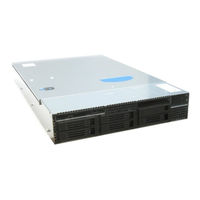
Intel SERVER SYSTEM SR2500AL Specification (42 pages)
Specification Update
Brand:
Intel
| Category:
Motherboard
| Size: 0.69 MB
Table of Contents
Revision History
2
Table of Contents
4
Preface
7
Summary Tables of Changes
8
Errata
11
IPMI over Serial Direct Connect Not Supported
11
Serial over LAN and IPMI over LAN Connections May Terminate Unexpectedly under Certain Conditions
11
Intermittent Beep Code 1-5-2-1 When Booting with Two Processors
11
Power Supply Population Errors May Not Display in the SEL
11
Fan 5 May Report a Reading of 0 RPM after the BMC Is Updated
12
The BMC May Not Respond to the IPMI Command, Send Message Sent Via LAN
12
Fans May Take a Long Time to Slow down after Fan Boosting
13
System Requires ~35 Seconds after AC Power Is Applied before the Power Button Responds
13
SEL Events for Hot-Swap Controller (HSC) May Appear after a DC Cycle
13
Fans May Run Faster than Expected after Exiting BIOS Setup
13
System Fault LED May Report Incorrect Status for some Events
14
Fan Removal Does Not Generate a SEL Event
14
Power Supply Redundancy State Is Misleading When Only One Power Supply Is Installed
15
Hot-Swap Controller (HSC) and Local Control Panel (LCP) Updates May Take a Long Time
15
Console Redirection Baud Rate Setting Auto Changing to 19.2K with Serial over LAN (SOL) Active
15
Serial over LAN (SOL) Unable to Redirect DOS Output
16
Password on Boot Not Supported
16
Intel® Embedded Server RAID Technology II Option Is Not Enabled in Initial BIOS
16
Release
16
HSC and BMC Versions Intermittently Not Seen in BIOS Setup
16
Intel® Server Boards S5000PAL/S5000XAL and Intel® Server System SR1500AL
17
Testing
17
Show a "Changes in Hardware or Drivers Detected" Error Message During WHQL ACPI Stress Testing
17
POST Leds Do Not Turn off after Operating System Loads
17
Checkup7.Exe (Microcode Update Utility) Is Not Storing Microcode in BIOS
18
Intel® RAID Controller SRCSAS144E Causes Systems to Reset Multiple Times before Completing POST
18
Change Logo Utility Does Not Save Modified BIOS Capsule Files with Correct Extension
19
PS/2 Keyboards and Mice May Stop Functioning after Red Hat* Enterprise Linux Is Installed
19
Failures Seen Installing to a SATA Drive When SATA Is Set to "Legacy" in the BIOS
20
Setup
20
System Hangs after Disabling On-Board Video in the BIOS Setup
20
The SMBIOS Entry Point May Not be Visible under Certain Hardware Configurations14
20
Suse* Linux Enterprise Server May Not Install Successfully with Intel® Embedded Server RAID Technology II Enabled
21
Red Hat* Enterprise Linux 4 and BIOS Setup Display a Different L2 Cache Size for the Quad-Core Intel® Xeon® Processor 5300 Series
22
Change Logo Utility Causes BIOS Corruption
22
Microsoft Windows System Event Viewer* May Record Error Event with ID 11
22
After the System Reboots, the POST Screen May Generate "NMI Has Been Received - System Halted" Message
23
Intel® RAID Web Console 2 Utility Displays "Unexpected Sensor" Warning Message in Microsoft Windows* Operating System
23
Random Drives May Go Offline When a Sixth Drive Is Installed and Intel® Embedded Server RAID Technology II Is Enabled in the Intel® Server System SR2500ALBRP
24
Dual Gigabit Expansion Module May Not Properly Reset
24
SAS Drive in a ROMB RAID 5 May Drop Offline During a Reboot in the Intel® Server System SR2500PALLX
25
Intel® Server System SR2500ALLX Sixth Hard Drive Filler Panel Is Difficult to
25
Remove
25
Suse* Linux Enterprise Server Unable to Boot after Basic Installation
26
Drives May Not be Detected or May Go Offline in the Intel® Server System SR2500ALBRP When Operating at SATA 3Gb/S Data Rate
26
New Versions of BMC Firmware with Previous Versions of BIOS Cause System POST Failure
27
Intel® Server System SR2500ALLX May Operate Louder than Expected
27
Red Hat* Enterprise Linux May Report the Wrong Processor Speed
27
The Suse* Linux Enterprise Server 10 Driver for SAS HW RAID Causes Unwanted Error Logs During Installation
27
IERR or Thermal Trip Event Reported in System Event Log (SEL) after System Power on
28
USB Device Generates "The Following Boot-Start or System-Start Driver(S) Failed to Load: I8042Prt" Error Message in Microsoft Windows* Operating Systems
29
Microsoft Windows* and Intel® RAID Web Console II Report an Error When the ASR2500SATAPE Kit Is Used
29
System May Log Ierrs When Running Certain Red Hat* Enterprise Linux Versions on the Intel® Server Board S5000PAL with Video Driver Ati_Drv.o 6.5.6
29
Microsoft Windows* Operating Systems Installed Without a Service Pack will Display Blue Screen with BIOS 79 and 81
30
Sluggish System Performance May be Experienced with BMC 60
31
Downgrading the Firmware of the Integrated RAID (ROMB), Intel® Embedded Server RAID Technology II, or SAS May Cause System Damage
31
In the Intel® Server Systems SR2500ALLX and SR1550ALSAS, Flashing of SAS
31
During SAS Controller Scanning
31
Firmware 1.22 and SAS BIOS 06.16.00 Makes Hard Drive #1 (Upper Left Drive Tray) Undetected During SAS Controller Scanning
31
Microsoft Windows 2003 R2 SP2* May Display Blue Screen During an Operating System Boot or Shutdown with a Specific Version of Intel I/OAT Driver
32
Server System Event Log (SEL) Time May be One Day Later than BIOS Time after Entering Year 2008
33
Performance Power Management Error in Microsoft Windows Server 2008
33
Midplane2 Hardware RAID Produces Unexpected Beep Sounds During System POST
34
Platform Confidence Test (PCT) Fails with BIOS 89/91 on Intel® Server Board S5000PAL/S5000XAL
34
USB Mouse May Hang in BIOS 94 RAID Console
34
PCI IBIST Error with BIOS 84
35
System May Hang During Login or Shutdown
35
Hard Disks Are Difficult to Install in Intel® Server System SR2500AL and Intel® Server Chassis SR2500
35
System will Not Skip CD/DVD Drive with BIOS Revision R0098 When RMM2 Installed
36
Please Use AXXMINIDIMM512 as the Replacement Solution for AXXMINIDIMM Which Is Eoled
37
Minus "Year" Number to Go Past "2000" at BIOS "System Date" Set up Interface will Cause the Server System to Hang
37
Please Do Not Downgrade BIOS from Factory Shipped BIOS 101 to any Previous Version
37
The Serial Port Console Redirection Displays the Adaptec® 5805 RAID
38
Documentation Changes
39
The SMBUS Block Diagram (Figure #16) Provided in Rev. 1.1 of the Intel Server Board S5000PAL/S5000XAL TPS Requires Changes to Accurately Reflect Production Hardware Design
39
The Power Block Diagram (Figure #25) as Provided in Rev. 1.1 of the Intel Server Board S5000PAL/S5000XAL TPS Does Not Reflect the Final, Production-Level Baseboard Design
40
SAS/SAS RAID Midplane Board (Figure #22) as Provided in Rev.1.0 of the Intel
41
Front Panel Pin-Out in the Intel
42
Advertisement
Advertisement
Related Products
Intel SR2500ALBRP - Server System - 0 MB RAM
Intel SR2500ALBRPR - Server System - 0 MB RAM
Intel SR2500ALLX - Server System - 0 MB RAM
Intel SR2500ALLXR - Server System - 0 MB RAM
Intel SR2520SAFRNA - Server System - 0 MB RAM
Intel SR2520SAX - Server System - 0 MB RAM
Intel SR2520SAXSNA - Server System - 0 MB RAM
Intel SR2520SAXR - Server System - 0 MB RAM
Intel SR2520SAFNA - Server System - 0 MB RAM
Intel SR2520SA
Intel Categories
Motherboard
Computer Hardware
Server
Server Board
Desktop
More Intel Manuals
Login
Sign In
OR
Sign in with Facebook
Sign in with Google
Upload manual
Upload from disk
Upload from URL