Sign In
Upload
Manuals
Brands
Intel Manuals
Chassis
SC5299-E DP
Intel SC5299-E DP Manuals
Manuals and User Guides for Intel SC5299-E DP. We have
7
Intel SC5299-E DP manuals available for free PDF download: User Manual, Technical Product Specification, Install Manual, Configuration Manual, Product Brief
Intel SC5299-E DP User Manual (174 pages)
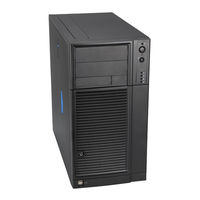
Server Chassis
Brand:
Intel
| Category:
Chassis
| Size: 5 MB
Table of Contents
Safety Information
3
Wichtige Sicherheitshinweise
3
Consignes de Sécurité
3
Instrucciones de Seguridad Importantes
3
Important Safety Instructions
3
Warnings
4
Preface
5
About this Manual
5
Product Contents, Order Options, and Accessories
5
Additional Information and Software
6
Table of Contents
9
Server Chassis Features
19
Figure 1. Front View of Intel
19
Table 1. Breakdown of Intel ® Entry Server Chassis SC5299-E Configurations
19
Table 2. Server Chassis Features
20
Component Identification
21
Front View Components
21
Figure 2. Front View Components (with Front Bezel Assembly)
21
Figure 3. Front View Components (Without Front Bezel Assembly)
22
Internal Components
23
Figure 4. Internal Components (DP/WS/BRP Configuration)
23
Figure 5. Internal Components (up Configuration)
24
Back Panel Components
25
Figure 6. Back Panel Components
25
Front Panel
26
Figure 7. Front Panel Components
26
Peripheral Devices
27
Hard Disk Drives
27
Figure 8. Optional Peripheral Devices (DP/WS/BRP Configuration Shown)
27
Front Bezel Assembly
28
Rack-Mounted Systems
28
Accessories and Order Codes
29
Figure 9. Mechanical Locks
29
Mechanical Locks
29
Table 3. Accessories and Order Codes
29
Hardware Installations and Upgrades
31
Before You Begin
31
Tools and Supplies Needed
31
System References
31
Removing and Installing the Left Side Cover
31
Removing the Left Side Cover
31
Installing the Left Side Cover
32
Figure 10. Removing Left Side Cover
32
Figure 11. Installing Left Side Cover
32
Removing and Installing the Right Side Cover
33
Removing the Right Side Cover
33
Figure 12. Removing Right Side Cover from Chassis
33
Installing the Right Side Cover
34
Figure 13. Re-Installing Right Side Cover on Chassis
34
Removing and Installing the Front Bezel Assembly
35
Removing the Front Bezel Assembly
35
Figure 14. Removing Front Bezel Assembly (DP/WS/BRP Configuration Shown)
35
Installing the Front Bezel Assembly
36
Figure 15. Installing the Front Bezel Assembly (DP/WS/BRP Configuration Shown)
36
Removing and Installing the Processor Air Duct
37
Removing the Processor Air Duct
37
Figure 16. Removing Processor Air Duct
37
Installing the Processor Air Duct
38
Installing or Removing a Server Board
38
Figure 17. Installing Processor Air Duct
38
Figure 18. Removing Drive Cage EMI Shield from Fixed Drive Cage (DP/WS/BRP Configuration Shown)
39
Figure 19. Removing Fixed Hard Drive Cage (DP/WS/BRP Configuration Shown)
40
Figure 20. Removing PCI Card Guide
40
Figure 21. Re-Installing PCI Card Guide into Chassis
41
Figure 22. Inserting Fixed Hard Drive Cage into Chassis (DP/WS/BRP Configuration Only)
42
Figure 23. Re-Attaching Drive Cage EMI Shield
43
Installing and Removing a Fixed Hard Drive
44
Installing a Fixed Hard Drive
44
Figure 24. Drive Bay Slot Order
44
Figure 25. Removing Drive Cage EMI Shield from Chassis (DP/WS/BRP Configuration Shown)
45
Figure 26. Removing PCI Card Guide
46
Figure 27. Routing Hard Drive Power Cables
46
Figure 28. Unlatching Drive Latch
47
Figure 29. Inserting Hard Drive into Drive Cage
47
Figure 30. Latching Drive Latch
48
Figure 31. Drive Bay Slot Order
48
Figure 32. Cabling a Fixed Hard Drive
49
Figure 33. Re-Installing Drive Cage EMI Shield
49
Removing a Fixed Hard Drive
50
Figure 34. Re-Installing PCI Card Guide
50
Figure 35. Removing Drive Cage EMI Shield from Chassis (DP/WS/BRP Configuration Shown)
51
Figure 36. Preparing Fixed Hard Drive for Removal
52
Figure 37. Removing Fixed Hard Drive from Drive Bay
52
Figure 38. Re-Installing Drive Cage EMI Shield
52
Installing or Removing a DVD-ROM or CD-ROM Drive
53
Installing a DVD-ROM or CD-ROM Drive
53
Figure 39. Removing 5.25-In Drive EMI Shield (DP/WS/BRP Configuration Shown)
53
Figure 40. Installing CD-ROM or DVD-ROM Drive (DP/WS/BRP Configuration Shown)
54
Removing a CD-ROM or DVD-ROM Drive
55
Figure 41. Removing CD-ROM or DVD-ROM Drive (DP/WS/BRP Configuration Shown)
55
Installing the Removing PCI Add-In Boards
56
Installing PCI Add-In Boards
56
Figure 42. Installing 5.25-In Drive EMI Shield (DP/WS/BRP Configuration Shown)
56
Figure 43. Opening PCI Add-In Card Retention Device (DP/WS/BRP Configuration Shown)
57
Figure 44. Removing PCI Slot Shield
57
Removing PCI Add-In Boards
58
Figure 45. Installing PCI Add-In Board
58
Figure 46. Opening PCI Add-In Card Retention Device (DP/WS/BRP Configuration Shown)
59
Figure 47. Removing PCI Add-In Board
59
Replacing the Front Panel Board
60
Figure 48. Replacing PCI Slot Shield
60
Figure 49. Removing Right Side Cover from Chassis
61
Figure 50. Unattaching Front Panel Board from Chassis
61
Figure 51. Removing Front Panel Board from Chassis
62
Figure 52. Removing Standoffs from Front Panel
62
Figure 53. Installing Front Panel Board in Chassis
63
Figure 54. Positioning Front Panel Board in Chassis
63
Replacing a System Fan
64
Figure 55. Re-Installing Right Side Cover on Chassis
64
Figure 56. Removing Fan Duct / System Fan Assembly (DP/WS/BRP Configuration)
65
Figure 57. Removing System Fan from Chassis (up Configuration)
65
Figure 58. Installing System Fan in Chassis (up Configuration)
66
Figure 59. Re-Installing Fan Duct / System Fan Assembly (DP/WS/BRP Configuration)
66
Replacing a Fixed Power Supply
67
Figure 60. Unlocking Fixed Power Supply from Chassis
67
Figure 61. Removing Fixed Power Supply from Chassis
68
Figure 62. Inserting Fixed Power Supply in Chassis
68
Figure 63. Locking Fixed Power Supply into Chassis
69
Installing an Additional Hot Swap Power Supply Module (BRP Configuration Only)
70
Figure 64. Removing Power Supply Filler Panel
70
Figure 65. Inserting Additional Hot Swap Power Supply Module
70
Replacing a Hot Swap Power Supply (BRP Configuration Only)
71
Figure 66. Removing Hot Swap Power Supply Module from Chassis
71
Figure 67. Inserting Hot Swap Power Supply Module in Chassis
71
Replacing a Hot Swap Power Supply Cage (BRP Configuration Only)
72
Figure 68. Removing Hot Swap Power Supply Module
72
Figure 69. Detaching Hot Swap Power Supply Cage from Inside of Chassis
73
Figure 70. Detaching Hot Swap Power Supply Cage from Rear of Chassis
73
Figure 71. Removing Rear Support Bracket from Hot Swap Power Supply Cage
74
Figure 72. Attaching Rear Support Bracket to Power Supply Cage
74
Figure 73. Securing Hot Swap Power Supply Cage to Rear of Chassis
75
Figure 74. Securing Hot Swap Power Supply Cage to Inside of Chassis
75
Figure 75. Re-Installing Hot Swap Power Supply Module(S)
76
Installing Feet for a Pedestal-Configured Chassis
77
Figure 76. Installing Feet on Chassis
77
Hot Swap Drive Cage Upgrade Install Instructions (Optional)
79
Before You Begin
79
Kits Required
79
Tools and Supplies Needed
79
System References
79
Installing a Hot Swap Hard Drive Cage with a SAS/SATA or SCSI Backplane
80
Figure 77. Removing Fixed Drive Cage EMI Shield from Chassis (DP/WS/BRP Configuration Shown)
80
Figure 78. Removing Fixed Hard Drive Cage from Chassis (DP/WS/BRP Configuration Shown)
81
Figure 79. Removing Stud Screws from Hot Swap Drive Cage
82
Figure 80. Attaching Latch Plate to Hot Swap Drive Cage
82
Figure 81. Attaching Filler Panel to Hot Swap Drive Cage
83
Figure 82. Removing Thumb Screws from Backplane
83
Figure 83. Attaching Fan Bracket to Hot Swap Drive Cage (SAS/SATA Drive Cage Illustrated)
84
Figure 84. Attaching Fan to Fan Bracket
85
Figure 85. Inserting Hot Swap Drive Cage into Chassis (DP/WS/BRP Configuration Shown)
86
Figure 86. Cabling the SCSI Hot Swap Drive Cage (DP/WS/BRP Configuration Shown)
87
Figure 87. Layout of Cable Connectors on the SAS/SATA Backplane (Backplane Without Expander Shown)
88
Figure 88. Making Six-Drive SAS/SATA Hot-Swap Drive Cage Backplane Without Expander Connections (DP/WS/BRP Configuration Shown - Fan Bracket Not Shown in the Illustration for Clarity)
89
Figure 89. Making Six-Drive Hot Swap Drive Cage Backplane with Expander Connections (DP/WS/BRP Configuration Shown - Fan Bracket Not Shown in the Illustration for Clarity)
90
Installing a Hot Swap Hard Drive
91
Figure 90. Opening Drive Bay Access Door
91
Figure 91. Releasing Drive Carrier from Hot Swap Drive Cage
92
Figure 92. Removing Retention Device from Drive Carrier
92
Figure 93. Installing Hard Drive into Drive Carrier
93
Figure 94. Re-Installing Drive Carrier in Hot Swap Drive Cage
93
Figure 95. Closing Drive Bay Access Door
94
Figure 96. Opening Drive Bay Access Door
94
Figure 97. Removing Drive Carrier from Hot Swap Drive Cage
95
Figure 98. Removing Hard Drive from Drive Carrier
95
Figure 99. Installing Hard Drive in Drive Carrier
96
Figure 100. Installing Plastic Retention Device in Drive Carrier
96
Figure 101. Re-Installing Drive Carrier in Hot Swap Drive Cage
97
Figure 102. Closing Drive Bay Access Door
97
Rack Mount Kit Install Instructions (Optional)
99
Before You Begin
99
Tools and Supplies Needed
99
System References
99
Setting up a Rack-Configured Chassis
99
Figure 103. Removing Chassis Feet
100
Figure 104. Removing Top Side Cover from Chassis
100
Figure 105. Removing PCI Card Guide
101
Figure 106. Removing Plastic Filler Panel from Chassis (DP/WS/BRP Configuration Shown)
102
Figure 107. Removing Plastic Plugs (DP/WS/BRP Configuration Shown)
103
Figure 108. Removing Rear Screws (DP/WS/BRP Configuration Shown)
103
Figure 109. Removing Plastic Plugs from Top Side Cover
104
Figure 110. Installing Rack Handle on Left Side Cover
104
Figure 111. Affixing Label to Front Panel
105
Figure 112. Installing Top Side Cover on Chassis
105
Figure 113. Detaching Inner Rack Rail from Rack Rail Assembly
106
Figure 114. Attaching Inner Rack Rails to Chassis (DP/WS/BRP Configuration Shown)
107
Figure 115. Attaching Outer Rack Rails to Rack Uprights
108
Figure 116. Installing Chassis into Rack
109
Technical Reference
111
Cable Routing
111
Power Supply Specifications
111
420-W Single Power Supply Input Voltages
111
420-W Single Power Supply Output Voltages
111
Table 4. 420-W Power Supply Output Capability
111
550-W Single Power Supply Input Voltages
112
550-W Single Power Supply Output Current
112
670-W Single Power Supply Output Voltages
112
Table 5. 550-W Power Supply Output Capability
112
Table 6. 670-W Power Supply Output Capability
112
650-W Single Power Supply Input Voltages
113
650-W Single Power Supply Output Voltages
113
System Environmental Specifications
113
Table 7. 650-W Power Supply Output Capability
113
Table 8. System Environmental Specifications
113
Safety Information
115
English
115
Server Safety Information
115
Safety Warnings and Cautions
115
Intended Application Uses
116
Site Selection
116
Equipment Handling Practices
116
Power and Electrical Warnings
116
System Access Warnings
117
Rack Mount Warnings
118
Electrostatic Discharge (ESD)
118
Other Hazards
119
Deutsch
120
Sicherheitshinweise für den Server
120
Sicherheitshinweise und Vorsichtsmaßnahmen
120
Zielbenutzer der Anwendung
121
Standortauswahl
121
Handhabung von Geräten
121
Warnungen zu Netzspannung und Elektrizität
122
Warnhinweise für den Systemzugang
123
Warnhinweise für Racks
124
Elektrostatische Entladungen (ESD)
124
Andere Gefahren
125
Français
126
Consignes de Sécurité Sur Le Serveur
126
Sécurité: Avertissements Et Mises en Garde
126
Domaines D'utilisation Prévus
127
Sélection D'un Emplacement
127
Pratiques de Manipulation de L'équipement
127
Alimentation Et Avertissements en Matière D'électricité
128
Avertissements Sur L'accès Au Système
129
Avertissements Sur Le Montage en Rack
130
Décharges Électrostatiques (ESD)
130
Autres Risques
131
Español
132
Información de Seguridad del Servidor
132
Advertencias y Precauciones sobre Seguridad
132
Aplicaciones y Usos Previstos
133
Selección de la Ubicación
133
Manipulación del Equipo
133
Advertencias de Alimentación y Eléctricas
134
Advertencias el Acceso al Sistema
135
Advertencias sobre el Montaje en Bastidor
136
Descarga Electrostática (ESD)
136
Installation/Assembly Safety Instructions
143
English
143
Deutsch
145
Français
148
Español
150
Italiano
152
Getting Help
155
World Wide Web
155
Telephone
155
U.S. and Canada
155
Europe
155
In Asia-Pacific Region
156
Japan
156
Latin America
156
Intel ® Server Issue Report Form
159
DIMM Configuration
160
Warranty
163
Limited Warranty for Intel® Chassis Subassembly Products
163
Extent of Limited Warranty
163
Warranty Limitations and Exclusions
164
Limitations of Liability
164
How to Obtain Warranty Service
164
Telephone Support
165
Returning a Defective Product
165
Advertisement
Intel SC5299-E DP User Manual (168 pages)
Entry Server Chassis
Brand:
Intel
| Category:
Chassis
| Size: 4 MB
Table of Contents
Safety Information
3
Important Safety Instructions
3
Wichtige Sicherheitshinweise
3
Consignes de Sécurité
3
Instrucciones de Seguridad Importantes
3
Warnings
4
Preface
5
About this Manual
5
Product Contents, Order Options, and Accessories
5
Manual Organization
5
Additional Information and Software
6
Table of Contents
9
Server Chassis Features
19
Figure 1. Front View of Intel
19
Table 1. Breakdown of Intel ® Entry Server Chassis SC5299-E Configurations
19
Table 2. Server Chassis Features
20
Component Identification
21
Front View Components
21
Figure 2. Front View Components (with Front Bezel Assembly)
21
Figure 3. Front View Components (Without Front Bezel Assembly)
22
Internal Components
23
Figure 4. Internal Components
23
Back Panel Components
24
Figure 5. Back Panel Components
24
Front Panel
25
Figure 6. Front Panel Components
25
Peripheral Devices
26
Hard Disk Drives
26
Figure 7. Optional Peripheral Devices
26
Front Bezel Assembly
27
Rack-Mounted Systems
27
Accessories and Order Codes
28
Figure 8. Mechanical Locks
28
Mechanical Locks
28
Table 3. Accessories and Order Codes
28
Hardware Installations and Upgrades
29
Before You Begin
29
Tools and Supplies Needed
29
System References
29
Removing and Installing the Left Side Cover
29
Removing the Left Side Cover
29
Installing the Left Side Cover
30
Figure 9. Removing Left Side Cover
30
Figure 10. Installing Left Side Cover
30
Removing and Installing the Front Bezel Assembly
31
Removing the Front Bezel Assembly
31
Figure 11. Removing Front Bezel Assembly
31
Installing the Front Bezel Assembly
32
Figure 12. Installing the Front Bezel Assembly
32
Removing and Installing the Processor Air Duct
33
Removing the Processor Air Duct
33
Installing the Processor Air Duct
33
Figure 13. Removing Processor Air Duct
33
Installing or Removing a Server Board
34
Figure 14. Installing Processor Air Duct
34
Figure 15. Removing Drive Cage EMI Shield from Fixed Drive Cage
35
Figure 16. Removing Fixed Hard Drive Cage
36
Figure 17. Removing PCI Card Guide
36
Figure 18. Re-Installing PCI Card Guide into Chassis
37
Figure 19. Inserting Fixed Hard Drive Cage into Chassis
38
Figure 20. Re-Attaching Drive Cage EMI Shield
39
Installing and Removing a Fixed Hard Drive
40
Installing a Fixed Hard Drive
40
Figure 21. Drive Bay Slot Order
40
Figure 22. Removing Drive Cage EMI Shield from Chassis
41
Figure 23. Removing PCI Card Guide
42
Figure 24. Routing Hard Drive Power Cables
42
Figure 25. Unlatching Drive Latch
43
Figure 26. Inserting Hard Drive into Drive Cage
43
Figure 27. Latching Drive Latch
44
Figure 28. Drive Bay Slot Order
44
Figure 29. Cabling a Fixed Hard Drive
45
Figure 30. Re-Installing Drive Cage EMI Shield
45
Removing a Fixed Hard Drive
46
Figure 31. Re-Installing PCI Card Guide
46
Figure 32. Preparing Fixed Hard Drive for Removal
47
Figure 33. Removing Fixed Hard Drive from Drive Bay
48
Figure 34. Re-Installing Drive Cage EMI Shield
48
Installing or Removing a DVD-ROM or CD-ROM Drive
49
Installing a DVD-ROM or CD-ROM Drive
49
Figure 35. Removing 5.25-In Drive EMI Shield
49
Figure 36. Installing CD-ROM or DVD-ROM Drive
50
Removing a CD-ROM or DVD-ROM Drive
51
Figure 37. Removing CD-ROM or DVD-ROM Drive
51
Installing the Removing PCI Add-In Boards
52
Installing PCI Add-In Boards
52
Figure 38. Installing 5.25-In Drive EMI Shield
52
Figure 39. Opening PCI Add-In Card Retention Device
53
Figure 40. Removing PCI Slot Shield
53
Removing PCI Add-In Boards
54
Figure 41. Installing PCI Add-In Board
54
Figure 42. Opening PCI Add-In Card Retention Device
55
Figure 43. Removing PCI Add-In Board
55
Replacing the Front Panel Board
56
Figure 44. Replacing PCI Slot Shield
56
Figure 45. Removing Right Side Cover from Chassis
57
Figure 46. Unattaching Front Panel Board from Chassis
57
Figure 47. Removing Front Panel Board from Chassis
58
Figure 48. Removing Standoffs from Front Panel
58
Figure 49. Installing Front Panel Board in Chassis
59
Figure 50. Positioning Front Panel Board in Chassis
59
Replacing a System Fan
60
Figure 51. Re-Installing Right Side Cover on Chassis
60
Figure 52. Removing Fan Duct / System Fan Assembly
61
Figure 53. Re-Installing Fan Duct / System Fan Assembly
61
Replacing a Fixed Power Supply
62
Figure 54. Unlocking Fixed Power Supply from Chassis
62
Figure 55. Removing Fixed Power Supply from Chassis
63
Figure 56. Inserting Fixed Power Supply in Chassis
63
Figure 57. Locking Fixed Power Supply into Chassis
64
Installing an Additional Hot Swap Power Supply Module (BRP Configuration Only)
65
Figure 58. Removing Power Supply Filler Panel
65
Figure 59. Inserting Additional Hot Swap Power Supply Module
65
Replacing a Hot Swap Power Supply (BRP Configuration Only)
66
Figure 60. Removing Hot Swap Power Supply Module from Chassis
66
Figure 61. Inserting Hot Swap Power Supply Module in Chassis
66
Replacing a Hot Swap Power Supply Cage (BRP Configuration Only)
67
Figure 62. Removing Hot Swap Power Supply Module
67
Figure 63. Detaching Hot Swap Power Supply Cage from Inside of Chassis
68
Figure 64. Detaching Hot Swap Power Supply Cage from Rear of Chassis
68
Figure 65. Removing Rear Support Bracket from Hot Swap Power Supply Cage
69
Figure 66. Attaching Rear Support Bracket to Power Supply Cage
69
Figure 67. Securing Hot Swap Power Supply Cage to Rear of Chassis
70
Figure 68. Securing Hot Swap Power Supply Cage to Inside of Chassis
70
Figure 69. Re-Installing Hot Swap Power Supply Module(S)
71
Installing Feet for a Pedestal-Configured Chassis
72
Figure 70. Installing Feet on Chassis
72
Hot Swap Drive Cage Upgrade Install Instructions (Optional)
73
Before You Begin
73
Kits Required
73
Tools and Supplies Needed
73
System References
73
Installing a Hot Swap Hard Drive Cage with a SAS/SATA or SCSI Backplane
74
Figure 71. Removing Fixed Drive Cage EMI Shield from Chassis
74
Figure 72. Removing Fixed Hard Drive Cage from Chassis
75
Figure 73. Removing Stud Screws from Hot Swap Drive Cage
76
Figure 74. Attaching Latch Plate to Hot Swap Drive Cage
76
Figure 75. Attaching Filler Panel to Hot Swap Drive Cage
77
Figure 76. Removing Thumb Screws from Backplane
77
Figure 77. Attaching Fan Bracket to Hot Swap Drive Cage (SAS/SATA Drive Cage Illustrated)
78
Figure 78. Attaching Fan to Fan Bracket
79
Figure 79. Inserting Hot Swap Drive Cage into Chassis
80
Figure 80. Cabling the SCSI Hot Swap Drive Cage
81
Figure 81. Layout of Cable Connectors on the SAS/SATA Backplane (Backplane Without Expander Shown)
82
Figure 82. Making Six-Drive SAS/SATA Hot-Swap Drive Cage Backplane Without Expander Connections (Fan Bracket Not Shown in the Illustration for Clarity)
83
Figure 83. Making Six-Drive Hot Swap Drive Cage Backplane with Expander Connections (Fan Bracket Not Shown in the Illustration for Clarity)
84
Installing a Hot Swap Hard Drive
85
Figure 84. Opening Drive Bay Access Door
85
Figure 85. Releasing Drive Carrier from Hot Swap Drive Cage
86
Figure 86. Removing Retention Device from Drive Carrier
86
Figure 87. Installing Hard Drive into Drive Carrier
87
Figure 88. Re-Installing Drive Carrier in Hot Swap Drive Cage
87
Figure 89. Closing Drive Bay Access Door
88
Figure 90. Opening Drive Bay Access Door
88
Figure 91. Removing Drive Carrier from Hot Swap Drive Cage
89
Figure 92. Removing Hard Drive from Drive Carrier
89
Figure 93. Installing Hard Drive in Drive Carrier
90
Figure 94. Installing Plastic Retention Device in Drive Carrier
90
Figure 95. Re-Installing Drive Carrier in Hot Swap Drive Cage
91
Figure 96. Closing Drive Bay Access Door
91
Rack Mount Kit Install Instructions (Optional)
93
Before You Begin
93
Tools and Supplies Needed
93
System References
93
Setting up a Rack-Configured Chassis
93
Figure 97. Removing Chassis Feet
94
Figure 98. Removing Top Side Cover from Chassis
94
Figure 99. Removing PCI Card Guide
95
Figure 100. Removing Plastic Filler Panel from Chassis
96
Figure 101. Removing Plastic Plugs
97
Figure 102. Removing Rear Screws
97
Figure 103. Removing Plastic Plugs from Top Side Cover
98
Figure 104. Installing Rack Handle on Left Side Cover
98
Figure 105. Affixing Label to Front Panel
99
Figure 106. Installing Top Side Cover on Chassis
99
Figure 107. Detaching Inner Rack Rail from Rack Rail Assembly
100
Figure 108. Attaching Inner Rack Rails to Chassis
101
Figure 109. Attaching Outer Rack Rails to Rack Uprights
102
Figure 110. Installing Chassis into Rack
103
Technical Reference
105
Cable Routing
105
Power Supply Specifications
105
550-W Single Power Supply Input Voltages
105
550-W Single Power Supply Output Current
105
Table 4. 550-W Power Supply Output Capability
105
670-W Single Power Supply Input Voltages
106
670-W Single Power Supply Output Voltages
106
Table 5. 670-W Power Supply Output Capability
106
Table 6. 650-W Power Supply Output Capability
106
System Environmental Specifications
107
Table 7. System Environmental Specifications
107
Safety Information
109
English
109
Server Safety Information
109
Safety Warnings and Cautions
109
Intended Application Uses
110
Site Selection
110
Equipment Handling Practices
110
Power and Electrical Warnings
110
System Access Warnings
111
Rack Mount Warnings
112
Electrostatic Discharge (ESD)
112
Other Hazards
113
Deutsch
114
Sicherheitshinweise für den Server
114
Sicherheitshinweise und Vorsichtsmaßnahmen
114
Zielbenutzer der Anwendung
115
Standortauswahl
115
Handhabung von Geräten
115
Warnungen zu Netzspannung und Elektrizität
116
Warnhinweise für den Systemzugang
117
Warnhinweise für Racks
118
Elektrostatische Entladungen (ESD)
118
Andere Gefahren
119
Français
120
Consignes de Sécurité Sur Le Serveur
120
Sécurité: Avertissements Et Mises en Garde
120
Domaines D'utilisation Prévus
121
Sélection D'un Emplacement
121
Pratiques de Manipulation de L'équipement
121
Alimentation Et Avertissements en Matière D'électricité
122
Avertissements Sur L'accès Au Système
123
Avertissements Sur Le Montage en Rack
124
Décharges Électrostatiques (ESD)
124
Autres Risques
125
Español
126
Información de Seguridad del Servidor
126
Advertencias y Precauciones sobre Seguridad
126
Aplicaciones y Usos Previstos
127
Selección de la Ubicación
127
Manipulación del Equipo
127
Advertencias de Alimentación y Eléctricas
128
Advertencias el Acceso al Sistema
129
Advertencias sobre el Montaje en Bastidor
130
Descarga Electrostática (ESD)
130
Installation/Assembly Safety Instructions
137
English
137
Deutsch
139
Français
142
Español
144
Italiano
146
Getting Help
149
World Wide Web
149
Telephone
149
U.S. and Canada
149
Europe
149
In Asia-Pacific Region
150
Japan
150
Latin America
150
Intel ® Server Issue Report Form
153
DIMM Configuration
154
Operating System Information
154
Hard Drive Information
155
Management Information
155
Complete Problem Description
156
Warranty
157
Limited Warranty for Intel® Chassis Subassembly Products
157
Extent of Limited Warranty
157
Warranty Limitations and Exclusions
158
Limitations of Liability
158
How to Obtain Warranty Service
158
Telephone Support
159
Returning a Defective Product
159
Intel SC5299-E DP Technical Product Specification (154 pages)
Entry Server Chassis
Brand:
Intel
| Category:
Chassis
| Size: 1 MB
Table of Contents
Revision History
2
Table of Contents
4
1 Product Overview
16
Intel® Entry Server Chassis SC5299-E Design Features
16
Chassis Views
18
Figure 1. Front Closed Chassis View of Intel
18
Figure 2. Rear Closed Chassis View of Intel Entry Server Chassis SC5299-E
19
Figure 3. Front Internal Chassis View of Intel
20
Figure 4. Rear Internal Chassis View of Intel
20
System Color
21
Chassis Security
21
I/O Panel
21
Rack and Cabinet Mounting Option
21
Figure 5. ATX 2.2 I/O Aperture
21
Front Bezel Features
22
Peripheral Bays
22
2 Power Sub-System
23
420-Watt Power Supply
23
Mechanical Overview
24
Figure 6. Mechanical Drawing for Power Supply Enclosure
24
Airflow and Temperature
25
Output Cable Harness
25
Table 2. Environmental Requirements
25
Figure 7. Output Cable Harness for 420-W Power Supply
26
Table 3. Cable Lengths
27
Table 4. P1 Baseboard Power Connector
27
Table 5. P2 Processor Power Connector
28
Table 6. P3-P6, P8-P9 Peripheral Connectors
28
AC Input Requirements
29
Table 7. P10 Right-Angle SATA Power Connector
29
Table 8. AC Input Rating
29
DC Output Specifications
31
Table 9. AC Line Sag Transient Performance
31
Table 10. AC Line Surge Transient Performance
31
Table 11. Load Ratings
32
Table 12. Voltage Regulation Limits
33
Table 13. Transient Load Requirements
33
Table 14. Capacitive Loading Conditions
34
Table 15. Ripple and Noise
34
Figure 8. Output Voltage Timing
35
Table 16. Output Voltage Timing
35
Table 17. Turn On/Off Timing
35
Protection Circuits
36
Table 18. over Voltage Protection Limits
37
Table 19. PSON# Signal Characteristic
38
Table 20. PWOK Signal Characteristics
38
550-Watt Power Supply
39
Mechanical Outline
40
Figure 9. Mechanical Drawing for Power Supply Enclosure
40
Figure 10. System Airflow Impedance
41
Table 21. Acoustic Requirements
41
AC Input Voltage Requirements
42
Table 22. Environmental Requirements
42
Table 23. AC Input Rating
42
Table 24. AC Line Sag Transient Performance
43
Table 25. AC Line Surge Transient Performance
43
Table 26. Performance Criteria
43
Table 27. AC Line Dropout/Holdup
45
Efficiency
46
DC Output Specifications
46
Table 28. Efficiency
46
Table 29. Cable Lengths
47
Table 30. P1 Main Power Connector
47
Table 31. P2 Processor Power Connector
48
Table 32. P12 Baseboard Power Connector
48
Table 33. P3, P4, P6, P7, P8, P9 Peripheral Power Connectors
48
Table 34. P5 Floppy Power Connector
49
Table 35. P10 SATA Power Connectors
49
Table 36. P11 SATA Power Connectors
49
Table 37. Load Ratings
50
Table 38. Power on Load Ratings
51
Table 39. Power on Voltage Regulation Limits
51
Table 40. Voltage Regulation Limits
52
Table 41. Transient Load Requirements
52
Table 42. Capacitive Loading Conditions
53
Table 43. Ripple and Noise
54
Table 44. Output Voltage Timing
54
Figure 11. Output Voltage Timing
55
Table 45. Turn On/Off Timing
55
Protection Circuits
56
Figure 12. Turn On/Off Timing (Power Supply Signals)
56
Table 46. Over-Current Protection
57
Table 47. Over-Voltage Protection Limits
57
Control and Indicator Functions
58
Table 48. PSON Signal Characteristic
58
Table 49. PWOK Signal Characteristics
59
650-W Power Supply Module
60
Mechanical Overview
60
AC Input Requirements
61
Table 50. Acoustic Requirements
61
Table 51. Thermal Requirements
61
Table 52. AC Input Rating
62
Table 53. AC Line Sag Transient Performance
62
Table 54. AC Line Surge Transient Performance
63
Table 55. Performance Criteria
63
Table 56. Holdup Requirements
64
DC Output Specification
66
Table 57. Edge Finger Power Supply Connector Pin-Out
66
Table 58. Power Supply Module Load Ratings
68
Table 59. Voltage Regulation Limits
68
Table 60. Transient Load Requirements
68
Table 61. Capacitive Loading Conditions
69
Table 62. Ripple and Noise
69
Figure 13. Output Voltage Timing
70
Figure 15. Output Voltage Timing
70
Table 63. Output Voltage Timing
70
Protection Circuits
72
Table 65. Over-Current Protection (OCP)
72
Control and Indicator Functions
73
Table 66. Over-Voltage Protection Limits
73
Table 67. PSON Signal Characteristic
74
Table 68. PSKILL Signal Characteristics
75
Table 69. PWOK Signal Characteristics
75
Smbus Monitoring Interface
76
Table 70. LED Indicators
76
650-W Power Distribution Board (PDB)
77
Table 71. Smbus Device Addressing
77
Figure 14. Mechanical Drawing for Dual (1+1 Configuration) Power Supply Enclosure
78
Mechanical Overview
78
Table 72. Environmental Requirements
78
DC Output Specification
79
Table 73. Edge Finger Power Supply Connector Pin-Out
79
Table 74. Cable Lengths
80
Table 75. P1 Baseboard Power Connector
81
Table 76. P2 Processor Power Connector
82
Table 77. P13 12V4 Power Connector
82
Table 78. Power Signal Connector
82
Table 79. Peripheral Power Connectors
83
Table 80. Floppy Power Connector
83
Table 81. 12V4 Power Connector
83
Table 82. SATA Power Connector
84
Table 83. +12V Outputs Load Ratings
84
DC/DC Converters Dynamic Loading
85
Table 84. DC/DC Converter Load Ratings
85
Table 85. Voltage Regulation Limits
85
Table 86. Transient Load Requirements
86
Table 87. Capacitive Loading Conditions
86
Table 88. Ripple and Noise
87
Table 89. Output Voltage Timing
87
Table 90. Turn On/Off Timing
88
Figure 16. Turn On/Off Timing (Power Supply Signals)
89
Table 1. Intel
89
Protection Circuits
90
Table 91. Over-Current Protection Limits/240Va Protection
90
Control and Indicator Functions (Hard-Wired)
91
Table 92. Over-Voltage Protection (OVP) Limits
91
Table 93. PSON Signal Characteristics
92
Table 94. PWOK Signal Characteristics
93
Table 95. Smbalert# Signal Characteristics
93
PSMI (Power Supply Monitoring Interface)
94
Table 96. Device Address Locations
94
670-W Power Supply
95
Mechanical Overview
95
Figure 17. Mechanical Drawing of the 670-W Power Supply Enclosure
96
Acoustic Requirements
97
Airflow Requirements
97
Temperature Requirements
97
Table 97. Sound Power Requirement
97
Table 98. Thermal Requirements
97
Output Wire Harness Drawing
98
Table 99. Cable Lengths
98
Figure 18. Output Harness for 670-W Power Supply
99
Power Connectors
100
Table 100. P1 Baseboard Power Connector
100
Table 101. P2 Processor Power Connector
101
Table 102. Power Signal Connector
101
Table 103. 12V4 Power Connector
102
Table 104. PCI Express Connector
102
Table 105. Peripheral Power Connectors
102
Table 106. P7 Right-Angle Peripheral Power Connector
103
Table 107. P5 Floppy Power Connector
103
Table 108. P12 Right-Angle SATA Power Connector
103
AC Input Requirements
104
Table 109. P13 SATA Power Connector
104
Table 110. AC Input Rating
105
Table 111. Efficiency
105
Table 112. AC Line Dropout/Holdup
105
Table 113. Performance Criteria
107
Table 114. AC Line Sag Transient Performance
108
Table 115. AC Line Surge Transient Performance
108
DC Output Specifications
109
Table 116. Load Ratings
110
Table 117. Voltage Regulation Limits
111
Table 118. Transient Load Requirements
111
Table 119. Capacitive Loading Conditions
111
Table 120. Pre-Set Lighter Load
112
Table 121. Pre-Set Lighter Voltage Regulation Limits
113
Table 122. Ripple and Noise
113
Figure 19. Output Voltage Timing
114
Table 123. Output Voltage Timing
114
Table 64. Turn On/Off Timing
115
Table 124. Turn On/Off Timing
115
Protection Circuits
116
Figure 20. Turn On/Off Timing (Power Supply Signals)
116
Table 125. Over-Current Protection (OCP)/240VA
116
Table 126. Over-Voltage Protection Limits
117
Control and Indicator Functions
118
Table 127. PSON Signal Characteristic
118
Table 128. PWOK Signal Characteristics
119
3 Chassis Cooling
120
Fan Configuration
120
Server Board Fan Control
120
Cooling Solution
121
Figure 21. Cooling Fan Configuration
121
4 Peripheral and Hard Drive Support
122
3.5-In Peripheral Drive Bay
122
5.25-In Peripheral Drive Bays
122
Figure 22. Drive Bay Locations for Intel
122
Hard Disk Drive Bays
123
Fixed Hard Drive Bay
123
Figure 23. 6-HDD Fixed Drive Bay, Rear Isometric View
123
SAS Non-Expander/Serial-ATA (SATA) Hot Swap Back Plane (HSBP)
124
Figure 24. Intel
125
Figure 25. Intel
127
Table 129. I C Bus Addressing
127
Table 130. I C Bus Loading
127
Connection Diagram
127
Table 131. GEM424* Controller GPIO Assignment
128
Table 132. LED Function
130
Table 133. 7-Pin SATA Connector Pin-Out
130
Table 134. 22-Pin SATA Connector Pin-Out
130
Table 135. Power Connector Pin-Out
131
Table 136. IPMB Header Pin-Out
132
Table 137. SATA Host I
132
Figure 26. Intel Entry Server Chassis SC5299-E 6HDD SATA Hot Swap Backplane Board Layout
133
Table 138. SATA Hot-Swap Backplane Connector Specifications
133
5 Standard Control Panel
135
Control Panel
135
Figure 27. Panel Controls and Indicators
135
Table 139. Control Panel LED Functions
136
6 Intel® Local Control Panel
137
Figure 28. SKU3 - Pedestal Server Application
137
Internal Control Panel Headers
138
Table 140. IPMI Header
138
7 System Interconnection
139
Signal Definitions
139
Chassis Internal Cables
139
Control Panel Cable
139
USB Cable
139
Fan Connector
139
Chassis Intrusion Cable
139
Server Board Internal Cables
139
Accessory Cables
139
I/O Panel Connectors
139
Spares and Accessories
140
8 Supported Intel® Server Boards
141
9 Regulatory, Environmentals, and Specifications
142
Product Regulatory Compliance
142
Product Safety Compliance
142
Product EMC Compliance - Class a Compliance
142
Product Ecology Requirements
143
Certifications/Registrations/Declarations
143
Product Regulatory Compliance Markings
144
Electromagnetic Compatibility Notices
145
FCC Verification Statement (USA)
145
ICES-003 (Canada)
145
Europe (CE Declaration of Conformity)
146
Japan EMC Compatibility
146
BSMI (Taiwan)
146
RRL (Korea)
146
Regulated Specified Components
147
End of Life/Product Recycling
147
Restriction of Hazardous Substances (Rohs) Compliance
147
Replacing the Back up Battery
148
System-Level Environmental Limits
148
BTU Information
149
Table 141. System Office Environment Summary
149
Table 142. System BTU Information Table
149
Serviceability and Availability
150
Table 143. Mean Time to Repair Estimate
150
Table 144. Intel
151
Advertisement
Intel SC5299-E DP Install Manual (34 pages)
Local Control Panel Kit for Entry Server Chassis
Brand:
Intel
| Category:
Chassis
| Size: 1 MB
Table of Contents
Safety Information
3
Important Safety Instructions
3
Wichtige Sicherheitshinweise
3
Consignes de Sécurité
3
Instrucciones de Seguridad Importantes
3
Table of Contents
5
Local Control Panel Kit Installation Instructions
9
Before You Begin
9
Kit Content List
9
Tools and Supplies Needed
10
System References
10
Installation Instructions for Intel® Server Chassis SC5300/SC5400
10
Remove Access Cover
10
Figure 1. Removing Access Cover
10
Remove Bezel Assembly
11
Figure 2. Removing Bezel Assembly
11
Remove Outer Bezel Door from Bezel Assembly
12
Figure 3. Removing Outer Bezel Door from Bezel Assembly
12
Remove Upper Third of Bezel Grill
13
Install LCP Grill
13
Figure 4. Removing Upper One-Third of Bezel Grill
13
Figure 5. Installing LCP Grill
13
Remove Lowest CD-ROM/DVD Drive Filler Panel
14
Figure 6. Removing Lowest Floppy/CD-ROM/DVD Drives or Filler Panel
14
Install EMI Shield Onto LCP Carrier
15
Inserting LCP Carrier into Drive Bay of Server Chassis
15
Figure 7. Installing EMI Shield on LCP Carrier
15
Figure 8. Attaching Drive Rails to LCP Carrier
15
Route LCP Cable
16
Figure 9. Installing LCP Carrier
16
Figure 10. Routing the LCP Cable
16
Connect LCP Cable to LCP Header of Server Board
17
Figure 11. Attaching LCP Cable to Header on Intel® Server Board SE7520AF2
17
Replace Bezel Assembly
18
Figure 12. Attaching LCP Cable to Header on Intel® Server Board SE7520BD2
18
Replace Access Cover
19
Figure 13. Installing Inner Bezel Door
19
Figure 14. Replacing Access Cover
19
Installation Instructions for Intel® Entry Server Chassis SC5275-E
20
Remove Access Cover
20
Figure 15. Removing Access Cover
20
Remove Bezel
21
Remove Lowest CD-ROM/DVD Drive Filler Panel
21
Figure 16. Removing Bezel
21
Figure 17. Removing Lowest Floppy/CD-ROM/DVD Drives or Filler Panel
21
Install EMI Shield Onto LCP Carrier
22
Inserting LCP Carrier into Drive Bay of Server Chassis
22
Figure 18. Installing EMI Shield on LCP Carrier
22
Figure 19. Installing Drive Rails to LCP Carrier
22
Figure 20. Inserting LCP Carrier into Drive Bay
23
Figure 21. Routing LCP Cable in Intel® Entry Server Chassis SC5275-E
23
Connect LCP Cable to LCP Header on Server Board
24
Figure 22. Attaching LCP Cable to Header on Intel® Server Board SE7520AF2
24
Replace Bezel
25
Figure 23. Attaching LCP Cable to Header on Intel® Server Board SE7520BD2
25
Replace Access Cover
26
Figure 24. Installing Bezel
26
Figure 25. Replacing Access Cover
26
Installation Instructions for Intel® Entry Server Chassis SC5299-E
27
Remove Access Cover
27
Remove Bezel
27
Figure 26. Removing Access Cover
27
Remove Lowest CD-ROM/DVD Drive Filler Panel
28
Figure 27. Removing Bezel
28
Figure 28. Removing Lowest Floppy/CD-ROM/DVD Drives or Filler Panel
28
Install EMI Shield Onto LCP Carrier
29
Figure 29. Installing EMI Shield on LCP Carrier
29
Inserting LCP Carrier into Drive Bay of Server Chassis
30
Route LCP Cable
30
Figure 30. Inserting LCP Carrier into Drive Bay
30
Figure 31. Routing LCP Cable
30
Connect LCP Cable to LCP Header on Server Board
31
Figure 32. Attaching LCP Cable to Header on Intel® Server Board S5000VSA
31
Figure 33. Attaching LCP Cable to Header on Intel® Server Board S5000PSL or Intel® Server Board XVN
31
Figure 34. Installing Bezel
32
Figure 35. Replacing Access Cover
33
Intel SC5299-E DP Configuration Manual (26 pages)
Server/Workstation Board and Server / Entry Server Chassis Parts List
Brand:
Intel
| Category:
Motherboard
| Size: 0 MB
Table of Contents
Contents
3
Table of Contents
3
Production SKU Details and Contents
4
Production Configuration and Ordering Steps
4
Production Configuration and Ordering Steps (S5000XVN)
8
Production Configuration
12
Production Board Skus
15
Production Chassis
16
Production Spares and Accessories
18
Production RAID Products
23
Vmware Vsphere* Virtualization Software Configuration Guide for Vsphere* Skus
25
Intel SC5299-E DP Configuration Manual (9 pages)
ServerBoard; Entry ServerChassis
Brand:
Intel
| Category:
Computer Hardware
| Size: 0 MB
Table of Contents
Contents
2
Change History
2
Table of Contents
3
Production Configurations
4
Production Board and Kdks
4
Production Order Codes
6
Production Board Accessories
7
Production Chassis
7
Production Chassis Accessories
7
Production Chassis Spares
8
Intel SC5299-E DP Product Brief (2 pages)
Server Chassis
Brand:
Intel
| Category:
Chassis
| Size: 0 MB
Advertisement
Related Products
Intel SC5299BRPNA
Intel SC5299DPNA
Intel SC5299WS
Intel SC5299BRP
Intel SC5299UP - Server Chassis Tower
Intel SC5295-E
Intel SC5299-E WS
Intel SC5299-E BRP
Intel SC5299-E UP
Intel SC5299-E Series
Intel Categories
Motherboard
Computer Hardware
Server
Desktop
Server Board
More Intel Manuals
Login
Sign In
OR
Sign in with Facebook
Sign in with Google
Upload manual
Upload from disk
Upload from URL