
Subscribe to Our Youtube Channel
Related Manuals for Intel SC5299BRP


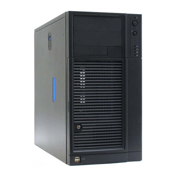
Summary of Contents for Intel SC5299BRP
- Page 1 Intel Entry Server Chassis SC5299-E ® Technical Product Specification Intel order number D37594-005 Revision 3.1 May 2010 Enterprise Platforms and Services Marketing...
-
Page 2: Revision History
Changed “Country” to “Region” in Section 9.1.5. July 2007 Added SC5299UP to SC5299-E family. November 2007 Added BTU information to SC5299-E family. December 2009 Updated section 1.1 and section 8. May 2010 Deleted CCC and CNCA content. Revision 3.1 Intel order number D37594-005... - Page 3 It is the responsibility of the system integrator that chooses not to use Intel developed server building blocks to consult vendor datasheets and operating parameters to determine the amount of air flow required for their specific application and environmental conditions.
-
Page 4: Table Of Contents
Table of Contents Intel Entry Server Chassis SC5299-E TPS Table of Contents 1. Product Overview ........................1 Intel® Entry Server Chassis SC5299-E Design Features ..........1 Chassis Views ......................3 System Color......................6 Chassis Security ......................6 I/O Panel ........................6 Rack and Cabinet Mounting Option................ - Page 5 Fixed Hard Drive Bay..................... 108 4.3.2 SAS Non-expander/Serial-ATA (SATA) Hot Swap Back Plane (HSBP) ....... 109 5. Standard Control Panel...................... 120 Control Panel......................120 6. Intel® Local Control Panel....................122 Internal Control Panel Headers ................123 Revision 3.1 Intel order number D37594-005...
- Page 6 Server Board Internal Cables.................. 124 Accessory Cables....................124 I/O Panel Connectors ..................... 124 Spares and Accessories ..................125 8. Supported Intel® Server Boards..................126 9. Regulatory, Environmentals, and Specifications .............. 127 Product Regulatory Compliance ................127 9.1.1 Product Safety Compliance ..................127 9.1.2...
- Page 7 ® Intel Entry Server Chassis SC5299-E TPS Table of Contents 9.10 Calculated MTBF....................135 Appendix A: Integration and Usage Tips ................. 137 Glossary ............................ 138 Revision 3.1 Intel order number D37594-005...
- Page 8 List of Figures Intel Entry Server Chassis SC5299-E TPS List of Figures ® Figure 1. Front Closed Chassis View of Intel Entry Server Chassis SC5299-E......3 ® Figure 2. Rear Closed Chassis View of Intel Entry Server Chassis SC5299-E ......4 ®...
- Page 9 ® Intel Entry Server Chassis SC5299-E TPS List of Figures Figure 29. Local Control Panel Components ................122 Revision 3.1 Intel order number D37594-005...
- Page 10 Table 27. AC Line Dropout/Holdup ..................... 30 Table 28. Efficiency........................31 Table 29. Cable Lengths......................32 Table 30. P1 Main Power Connector ..................32 Table 31. P2 Processor Power Connector.................. 33 Table 32. P12 Baseboard Power Connector ................33 Revision 3.1 Intel order number D37594-005...
- Page 11 Table 62. Ripple and Noise......................54 Table 63. Output Voltage Timing ....................55 Table 64. Turn On/Off Timing ..................... 56 Table 65. Over-current Protection (OCP) ................... 57 Table 66. Over-voltage Protection Limits..................58 Table 67. PSON Signal Characteristic..................59 Revision 3.1 Intel order number D37594-005...
- Page 12 Table 97. Sound Power Requirement..................82 Table 98. Thermal Requirements ....................82 Table 99. Cable Lengths......................83 Table 100. P1 Baseboard Power Connector ................85 Table 101. P2 Processor Power Connector................86 Table 102. Power Signal Connector ................... 86 Revision 3.1 Intel order number D37594-005...
- Page 13 Table 133. 7-Pin SATA Connector Pin-out ................115 Table 134. 22-Pin SATA Connector Pin-out ................115 Table 135. Power Connector Pin-out..................116 Table 136. IPMB Header Pin-out ....................117 Table 137. SATA Host I C Header Pin-out ................117 Revision 3.1 xiii Intel order number D37594-005...
- Page 14 Table 141. System Office Environment Summary ..............134 Table 142. System BTU Information Table................134 Table 143. Mean Time To Repair Estimate ................135 ® Table 144. Intel Entry Server Chassis SC5299-E Component MTBF........136 Revision 3.1 Intel order number D37594-005...
- Page 15 ® Intel Entry Server Chassis SC5299-E TPS List of Tables <This page intentionally left blank.> Revision 3.1 Intel order number D37594-005...
-
Page 16: Product Overview
SC5299BRP – 650-W 1+1 redundant PSU for dual-processor server boards The UP, DP and WS power supply configurations each include an Intel validated PSU with an integrated cooling fan and one AC line input. The BRP power supply configuration includes (1 of 2) redundant Intel validated PSU with an integrated cooling fan and one AC line input. - Page 17 5.2U tower, convertible to 6U rack mount Front Panel LEDs for NIC1, NIC2, HDD activity, power status, and system fault status. Switches for power, NMI, and reset. Integrated temperature sensor for fan speed management. External front Two USB ports Revision 3.1 Intel order number D37594-005...
-
Page 18: Chassis Views
SC5299BRP SC5299WS connectors Color Black Construction 1.0-mm, zinc-plated sheet metal, meets Intel Cosmetic Spec # C25432 Chassis ABS Fire retardant, non- brominated, PC-ABS Dimensions 17.8 in (45.2 cm) x 9.256 in (23.5 cm) x 19 in (48.3 cm) Pedestal Dimensions 9.256 in (23.5 cm) x 17.6 in (44.7 cm) x 19 in (48.3 cm) -
Page 19: Figure 2. Rear Closed Chassis View Of Intel Entry Server Chassis Sc5299-E
120-mm system fan G. Serial B port knockout H. Location to install padlock loop External SCSI knockout Alternate Serial B port knockout ® Figure 2. Rear Closed Chassis View of Intel Entry Server Chassis SC5299-E Revision 3.1 Intel order number D37594-005... -
Page 20: Figure 3. Front Internal Chassis View Of Intel
® Intel Entry Server Chassis SC5299-E TPS Product Overview AF000447 ® Figure 3. Front Internal Chassis View of Intel Entry Server Chassis SC5299-E(DP/WS/BRP configuration shown) TP00868 ® Figure 4. Rear Internal Chassis View of Intel Entry Server Chassis SC5299-E with Optional Hot- swap Drive Bay Revision 3.1... -
Page 21: System Color
Note: See the technical product specification appropriate to the server board for a description of BIOS and management security features for each specific supported platform. Technical product specifications can be found at http://intel.com/support. I/O Panel All input/output (I/O) connectors are accessible from the rear of the chassis. The SSI E-bay 3.61-compliant chassis provides an ATX 2.2-compatible cutout for I/O shield installation. -
Page 22: Front Bezel Features
Peripheral Bays Two 5.25-in, half-height drive bays are available for CD/DVD-ROM or tape drives as well as one 3.5-inch removable media drive bay. Drive installation is tool-less and requires no screws. Revision 3.1 Intel order number D37594-005... -
Page 23: Power Sub-System
ITE equipment. The power supply is tested as described in JEIDA MITI Guideline for Suppression of High Harmonics in Appliances and General-Use Equipment and meets the harmonic current emissions limits specified for ITE equipment. Revision 3.1 Intel order number D37594-005... -
Page 24: Mechanical Overview
® Intel Entry Server Chassis SC5299-E TPS Power Sub-system 2.1.1 Mechanical Overview Figure 6. Mechanical Drawing for Power Supply Enclosure Revision 3.1 Intel order number D37594-005... -
Page 25: Airflow And Temperature
“Handle, knobs, grips, etc. held for short periods of time only”. 2.1.3 Output Cable Harness Listed or recognized component appliance wiring material (AVLV2), CN, rated min 105 C, 300Vdc is used for all output wiring. Revision 3.1 Intel order number D37594-005... -
Page 26: Figure 7. Output Cable Harness For 420-W Power Supply
3. INSTALL 1 TIE WRAP WITHIN 12MM OF THE PSU CAGE 4. MARK REFERENCE DESIGNATOR ON EACH CONNECTOR 5. TIE WRAP EACH HARNESS AT APPROX. MID POINT 6. TIE WRAP P1 WITH 2 TIES AT APPROXIMATELY 15M SPACING. Revision 3.1 Intel order number D37594-005... -
Page 27: Table 3. Cable Lengths
+3.3 VDC Orange +3.3 VDC* Orange +3.3 VDC Orange -12 VDC Blue Black Black +5 VDC PSON# Green Black Black +5 VDC Black Black Black PWR OK Gray Reserved N.C. 5VSB Purple +5 VDC Revision 3.1 Intel order number D37594-005... -
Page 28: Table 5. P2 Processor Power Connector
Connector housing: AMP* V0 P/N is 770827-1 or equivalent Contact: AMP* 61314-1 contact or equivalent Table 6. P3-P6, P8-P9 Peripheral Connectors Signal 18 AWG Color +12 V2 Blue/White Black Black +5 VDC 2.1.3.4 P10 Right-angle, P11 SATA Power Connectors Connector Housing: Contact: Revision 3.1 Intel order number D37594-005... -
Page 29: Ac Input Requirements
During an AC dropout of one cycle or less the power supply meets dynamic voltage regulation requirements over the rated load. An AC line dropout of one cycle or Revision 3.1 Intel order number D37594-005... - Page 30 “Surge” will be defined to refer to conditions when the AC line voltage rises above nominal voltage. The power supply meets the requirements under the following AC line sag and surge conditions. Revision 3.1 Intel order number D37594-005...
-
Page 31: Dc Output Specifications
The output connector ground pins are connected to safety ground (power supply enclosure). 2.1.5.2 Standby Output The 5VSB output is present when an AC input greater than the power supply turn-on voltage is applied. Revision 3.1 Intel order number D37594-005... -
Page 32: Table 11. Load Ratings
12V1 and 12V2 combined peak current does not exceed 34 A for over 12 seconds. All outputs remain within regulation limits. Maximum power does not exceed 450 W at 25 degrees C ambient and 420 W at 50 degrees C ambient. Revision 3.1 Intel order number D37594-005... -
Page 33: Table 12. Voltage Regulation Limits
Output Range MAX Step Voltage Overshoot/Undershoot +12V1DC 0.5A TO 18A 350mV (700mVpk-pk) +12V2DC 0.5A TO 15A 350mV (700mVpk-pk) +5VDC 2A TO 20A 200mV(400mVpk-pk) +3.3VDC 0.5A TO 17A 200mV (400mVpk-pk) +5VSB 0.1A TO 2.0A 0.7A 250mV(500mVpk-pk) Revision 3.1 Intel order number D37594-005... -
Page 34: Table 14. Capacitive Loading Conditions
) of each other during turn off. The vout_off following figure shows the timing requirements for the power supply being turned on and off via the AC input, with PSON held low and the PSON signal, with the AC input applied. Revision 3.1 Intel order number D37594-005... -
Page 35: Figure 8. Output Voltage Timing
Delay from AC being applied to 5VSB being within msec sb_on_delay 1000 regulation. Delay from AC being applied to all output voltages being msec ac_on_delay 2500 within regulation. Time all output voltages stay within regulation after loss of msec vout_holdup Revision 3.1 Intel order number D37594-005... -
Page 36: Protection Circuits
The power supply over voltage protection is locally sensed. The power supply will shut down and latch off after an over voltage condition occurs. This latch can be cleared by toggling the PSON signal or by an AC power interruption. The following table contains the over voltage Revision 3.1 Intel order number D37594-005... -
Page 37: Table 18. Over Voltage Protection Limits
+3.3V, +5V, +12V, and -12V power rails. When this signal is not pulled low by the system, or left open, the outputs (except the +5VSB) turn off. This signal is pulled to a standby voltage by a pull-up resistor internal to the power supply. Revision 3.1 Intel order number D37594-005... -
Page 38: Table 19. Pson# Signal Characteristic
Logic level high voltage, Isource=200 A Sink current, PWOK = low Source current, PWOK = high PWOK delay: T 100ms 1000ms pwok_on PWOK rise and fall time 100 sec Power down delay: T 200msec pwok_off Revision 3.1 Intel order number D37594-005... -
Page 39: 550-Watt Power Supply
EN55022/CISPR 22 – Class A (10dB margin) @ 75% load Reliability: 100,000 hours MTBF and 3 year life @ 75% load, 40 degrees C, 100VAC Standard Intel component de-ratings Ecology: RoHS compliant per directive 2002/95/EC (lead free solder) Revision 3.1... -
Page 40: Mechanical Outline
The power supply shall incorporate an 80-mm fan for self cooling and system cooling. The airflow direction shall be from the wire internal face of the power supply to the external face. The power supply shall have adequate airflow with the following system airflow restriction. Revision 3.1 Intel order number D37594-005... -
Page 41: Figure 10. System Airflow Impedance
) from the inlet to the outlet of the power supply does not exceed 20 degrees C. All airflow passes through the power supply and not over the exterior surfaces of the power supply. Revision 3.1 Intel order number D37594-005... -
Page 42: Ac Input Voltage Requirements
“Surge” will be defined to refer to conditions when the AC line voltage rises above nominal voltage. The power supply meets the requirements under the following AC line sag and surge conditions. Revision 3.1 Intel order number D37594-005... -
Page 43: Table 24. Ac Line Sag Transient Performance
Electrostatic Discharge Susceptibility The power supply complies with the limits defined in EN 55024: 1998 using the IEC 61000-4- 2:1995 and the level 3 test standard and performance criteria B defined in Annex B of CISPR Revision 3.1 Intel order number D37594-005... - Page 44 The power supply meets the AC dropout requirement over rated AC voltages, frequencies. A dropout of the AC line for any duration does not cause damage to the power supply. Revision 3.1 Intel order number D37594-005...
-
Page 45: Table 27. Ac Line Dropout/Holdup
11:1995 test standard and performance criteria C defined in Annex B of CISPR 24. In addition, the power supply meets the following Intel Requirement: A continuous input voltage below the nominal input range shall not damage the power supply or cause overstress to any power supply component. -
Page 46: Efficiency
20% of Maximum Recommended Efficiency 2.2.4 DC Output Specifications 2.2.4.1 Output Connectors Listed or recognized component appliance wiring material (AVLV2), CN, rated minimum 105 degrees C , 300VDC is used for all output wiring. Revision 3.1 Intel order number D37594-005... -
Page 47: Table 29. Cable Lengths
+5 VDC Black Black COMRS Black (24AWG) +5 VDC Black Black Black PWR OK Gray Reserved N.C. 5VSB Purple +5 VDC +12V2 Yellow +5 VDC +12V2 Yellow +5 VDC 12VRS Yellow/White (24AWG) 5VRS Red/White (24AWG) Revision 3.1 Intel order number D37594-005... -
Page 48: Table 31. P2 Processor Power Connector
Connector housing: AMP* 1-480424-0 or equivalent Contact: Amp 61314-1 contact or equivalent Table 33. P3, P4, P6, P7, P8, P9 Peripheral Power Connectors Signal 18 AWG Color +12 V2 Green Black Black +5 VDC Revision 3.1 Intel order number D37594-005... -
Page 49: Table 34. P5 Floppy Power Connector
+5VDC Black +12V2 Green 2.2.4.8 P11 SATA Power Connector Connector housing: JWT A3811H00-5P or equivalent Contact: JWT A3811TOP-0D or equivalent Table 36. P11 SATA Power Connectors Signal 18 AWG Color +3.3V Orange Black +5VDC Revision 3.1 Intel order number D37594-005... -
Page 50: Table 37. Load Ratings
The power supply operates at lighter load conditions when the system first powers on. Under these conditions, the voltage regulation limits are relaxed. Power on loading and voltage regulation requirements are defined in the following tables. Time duration is 1 second during power on. Revision 3.1 Intel order number D37594-005... -
Page 51: Table 38. Power On Load Ratings
200mV drop on the +3.3V output. The remote sense return (ReturnS) must be able to regulate out a minimum of 200mV drop in the power Revision 3.1 Intel order number D37594-005... -
Page 52: Table 40. Voltage Regulation Limits
MIN load and MAX load conditions. Table 41. Transient Load Requirements Output Step Load Size (see Load Slew Rate Test Capacitive Load note 2) 250 F +3.3VDC 5.0A 0.25 A/ sec 4.0A 0.25 A/ sec 400 F Revision 3.1 Intel order number D37594-005... -
Page 53: Table 42. Capacitive Loading Conditions
This is measured over a bandwidth of 0 Hz to 20 MHz at the power supply output connectors. A 10 F tantalum capacitor, in parallel with a 0.1 F ceramic capacitor, is placed at the point of measurement. Revision 3.1 Intel order number D37594-005... -
Page 54: Table 43. Ripple And Noise
All main outputs must be within regulation of each msec vout_on other within this time. All main outputs must leave regulation within this msec vout_off time. * The 5VSB output voltage rise time shall be from 1.0 ms to 25.0 ms. Revision 3.1 Intel order number D37594-005... -
Page 55: Figure 11. Output Voltage Timing
Delay from PWOK de-asserted to output voltages (3.3V, 5V, msec pwok_off 12V, -12V) dropping out of regulation limits. Duration of PWOK being in the de-asserted state during an msec pwok_low off/on cycle using AC or the PSON signal. Revision 3.1 Intel order number D37594-005... -
Page 56: Protection Circuits
Protection circuits inside the power supply cause only the power supply’s main outputs to shutdown. If the power supply latches off due to a protection circuit tripping, an AC cycle OFF for 15sec and a PSON# cycle HIGH for 1 sec will reset the power supply. Revision 3.1 Intel order number D37594-005... -
Page 57: Table 46. Over-Current Protection
Exception: The +5VSB rail should be able to recover after its over voltage condition occurs. Table 47. Over-voltage Protection Limits Output Voltage MIN (V) MAX (V) +3.3V +12V1,2 13.3 14.5 -12V -13.3 -15.6 +5VSB Revision 3.1 Intel order number D37594-005... -
Page 58: Control And Indicator Functions
PWOK will be de-asserted to a LOW state. The start of the PWOK delay time is inhibited as long as any power supply output is in current limit. Revision 3.1 Intel order number D37594-005... -
Page 59: Table 49. Pwok Signal Characteristics
Logic level high voltage, Isource=200 A Sink current, PWOK = low Source current, PWOK = high PWOK delay: T 100ms 1000ms pwok_on PWOK rise and fall time 100 sec Power down delay: T 200msec pwok_off Revision 3.1 Intel order number D37594-005... -
Page 60: 650-W Power Supply Module
The 650-W power supply module specification defines a 1+1 redundant power supply that ® ® supports a dual-processor Intel Xeon server system. The power supply has two outputs to power the system: 12VDC and 5VSB. A separate cage (including the power distribution board) is designed to plug directly to the output connector of the power supply module and provide additional power converters to produce other required voltages. -
Page 61: Ac Input Requirements
EN61000-3-2 and JEIDA MITI standards. 2.3.2.1 AC Inlet Connector The AC input connector is an IEC 320 C-14 power inlet. This inlet is rated for 10A/250VAC. Revision 3.1 Intel order number D37594-005... -
Page 62: Table 52. Ac Input Rating
Loading Performance Criteria Voltage Continuous Nominal AC 50/60Hz 100% No loss of function or performance Voltage ranges 0 to 1 AC 100% Nominal AC 50/60Hz No loss of function or performance cycle Voltage ranges Revision 3.1 Intel order number D37594-005... -
Page 63: Table 54. Ac Line Surge Transient Performance
The apparatus shall continue to operate as intended. No degradation of performance beyond spec limits. Temporary loss of function is allowed provided the function is self-recoverable or can be restored by the operation of the controls. Revision 3.1 Intel order number D37594-005... -
Page 64: Table 56. Holdup Requirements
The power supply meets the AC dropout requirement over rated AC voltages and frequencies. A dropout of the AC line for any duration will not cause damage to the power supply. Revision 3.1 Intel order number D37594-005... - Page 65 The power supply complies with the limits defined in EN55024: 1998 using the IEC 61000-4- 11:1995 test standard and performance criteria C defined in Annex B of CISPR 24. In addition, the power supply meets the following Intel Requirement: o A continuous input voltage below the nominal input range shall not damage the power supply or cause overstress to any power supply component.
-
Page 66: Dc Output Specification
+12V +12V connector: 2X24 +12V +12V +12V +12V +12V +12V +12V +12V +12V +12V +12V +12V +12V +12V +12V Return +12V Return +12V Return +12V Return +12V Return +12V Return +12V Return +12V Return Revision 3.1 Intel order number D37594-005... - Page 67 Also, the power supply supplies the listed peak currents and power for a minimum of 10 seconds. Outputs are not required to be peak loaded simultaneously. Revision 3.1 Intel order number D37594-005...
-
Page 68: Table 58. Power Supply Module Load Ratings
2200 F +5VSB 0.5 A 0.5 A/ s 20 F Notes: Step loads on each 12V output may happen simultaneously. The +12V should be tested with 2200 F evenly split between the three +12V rails. Revision 3.1 Intel order number D37594-005... -
Page 69: Table 61. Capacitive Loading Conditions
(passive sharing). The 5Vsb outputs of the power supplies are connected together in the system so that a failure or hot swap of a redundant power supply does not cause these outputs to go out of regulation in the system. Revision 3.1 Intel order number D37594-005... -
Page 70: Figure 13. Output Voltage Timing
* The 5VSB output voltage rise time shall be from 1.0 ms to 25.0 ms. V out 10% V out T vout_off T vout_rise T vout_on TP02313 Figure 13. Output Voltage Timing Revision 3.1 Intel order number D37594-005... - Page 71 The newly inserted power supply will get turned on into standby or Power On mode once inserted. Revision 3.1 Intel order number D37594-005...
-
Page 72: Protection Circuits
Table 65. Over-current Protection (OCP) Output Over-current Protection Limits Voltage +12V 120% min (= 65.0 A min); 140% max (= 76.0 A max) +5VSB 120% min (= 3.6 A min); 200% max (= 6.0 A max) Revision 3.1 Intel order number D37594-005... -
Page 73: Control And Indicator Functions
+12V power rail. When this signal is not pulled low by the system, or left open, the outputs (except for the +5VSB) turn off. This signal is pulled to a standby voltage by a pull-up resistor internal to the power supply. Revision 3.1 Intel order number D37594-005... -
Page 74: Table 67. Pson Signal Characteristic
Upon receiving a LOW state signal at the PSKill pin, the power supply will be allowed to turn on via the PSON# signal. A logic LOW on this pin by itself should not turn on the power outputs. Revision 3.1 Intel order number D37594-005... -
Page 75: Table 68. Pskill Signal Characteristics
Sink current, PWOK = low 4 mA Source current, PWOK = high 2 mA PWOK delay: T 100 ms 1000 ms pwok_on PWOK rise and fall time 100 s Power down delay: T 1 ms 200 ms pwok_off Revision 3.1 Intel order number D37594-005... -
Page 76: Smbus Monitoring Interface
A0 and A1. The circuits inside the power supply derive their power from the standby output. For redundant power supplies, the device(s) are powered from the system side of the or’ing device. Revision 3.1 Intel order number D37594-005... -
Page 77: 650-W Power Distribution Board (Pdb)
DC/DC power converters to produce other required voltages: +3.3VDC, +5VDC and – 12VDC, along with additional 12V rail 240VA protection and a FRU EEPROM. Revision 3.1 Intel order number D37594-005... -
Page 78: Mechanical Overview
There is no fan in the cage; the cage is cooled by the fan in the power supply module(s) when combined together in the system. 2.4.1.2 Temperature Requirements The PDB operates within all specified limits over the T temperature range. Table 72. Environmental Requirements Item Description Units Operating temperature range. Revision 3.1 Intel order number D37594-005... -
Page 79: Dc Output Specification
+12V +12V +12V Return +12V Return +12V Return +12V Return +12V Return +12V Return +12V Return +12V Return +12V Return +12V Return +12V Return +12V Return +12V Return +12V Return +12V Return +12V Return Revision 3.1 Intel order number D37594-005... -
Page 80: Table 74. Cable Lengths
Power Supply cover exit hole Peripheral Power Connector Extension Peripheral Power Connector Power Supply cover exit hole Peripheral Power Connector Extension Peripheral Power Connector Power Supply cover exit hole Right-angle SATA Power Connector Extension Right-angle SATA Power Connector Revision 3.1 Intel order number D37594-005... -
Page 81: Table 75. P1 Baseboard Power Connector
Black 5V RS Red (24AWG) Black Black Reserved N.C. +5VDC +5VDC Black +5VDC PWR OK Gray (24AWG) +5VDC 5 VSB Purple Black +12V3 Yellow +12V3 Yellow +3.3VDC Orange Note: Remote Sense wire double crimped. Revision 3.1 Intel order number D37594-005... -
Page 82: Table 76. P2 Processor Power Connector
Power Signal Connector (P12) Connector housing: 5-Pin Molex* 50-57-9405 or equivalent Contacts: Molex 16-02-0087 or equivalent Table 78. Power Signal Connector Signal 24 AWG Color I2C Clock White I2C Data Yellow SMBAlert# Black 3.3RS Orange Revision 3.1 Intel order number D37594-005... -
Page 83: Table 79. Peripheral Power Connectors
Contact: Molex Mini-Fit Jr, HCS, 44476-1111 or equivalent Table 81. 12V4 Power Connector Signal 18 AWG Color Black Black +12V4 Green +12V4 Green 2.4.2.10 Right-angle SATA Power Connectors (P10, P11) Connector housing: JWT* F6002HS0-5P-18 or equivalent Revision 3.1 Intel order number D37594-005... -
Page 84: Table 82. Sata Power Connector
12V maximum output current is 54 A. Peak power and current loading shall be supported for a minimum of 12 seconds. 12V5 is the power source for the three DC-DC converters to generate 3.3V, 5V, and -12V. Revision 3.1 Intel order number D37594-005... -
Page 85: Dc/Dc Converters Dynamic Loading
DC/DC Converters Dynamic Loading The output voltages remain within limits specified for step loading and capacitive loading, as specified in the following table. The load transient repetition rate is tested between 50 Hz and 5 Revision 3.1 Intel order number D37594-005... -
Page 86: Table 86. Transient Load Requirements
A minimum of 45 degrees phase margin and –10dB-gain margin is required. 2.4.3.3 Common Mode Noise The common mode noise on any output does not exceed 350 mV peak-peak over the frequency band of 10 Hz to 30 MHz. Revision 3.1 Intel order number D37594-005... -
Page 87: Table 88. Ripple And Noise
All main outputs must be within regulation of each msec vout_on other within this time. All main outputs must leave regulation within this msec vout_off time. * The 5VSB output voltage rise time shall be from 1.0 ms to 25.0 ms. Revision 3.1 Intel order number D37594-005... -
Page 88: Table 90. Turn On/Off Timing
Delay from PSON active to output voltages within pson_on_delay regulation limits. Delay from PSON deactive to PWOK being de- pson_pwok asserted. Delay from output voltages within regulation limits to pwok_on PWOK asserted at turn on. Revision 3.1 Intel order number D37594-005... -
Page 89: Figure 16. Turn On/Off Timing (Power Supply Signals)
It also does not trip the power supply protection circuits during turn on. Revision 3.1 Intel order number D37594-005... -
Page 90: Protection Circuits
150% max (= 36A max) 110% min (= 33A min) 150% max (= 45A max) -12V 0.625A 2.0A +12V1 20Amax +12V2 20Amax +12V3 20A max +12V4 20A max +5VSB See the Power Supply specification for details. Revision 3.1 Intel order number D37594-005... -
Page 91: Control And Indicator Functions (Hard-Wired)
+3.3V, +5V, +12V, and -12V power rails. When this signal is not pulled low by the system, or left open, the outputs (except for the +5VSB) turn off. This signal is pulled to a standby voltage by a pull-up resistor internal to the power supply. Revision 3.1 Intel order number D37594-005... -
Page 92: Table 93. Pson Signal Characteristics
PWOK will be de-asserted to a LOW state. The start of the PWOK delay time is inhibited as long as any power supply output is within current limit. Revision 3.1 Intel order number D37594-005... -
Page 93: Table 94. Pwok Signal Characteristics
Logic level low voltage, Isink=4 mA 0.4 V Logic level high voltage, Isink=50 A 5.25 V Sink current, Alert# = low 4 mA Sink current, Alert# = high 50 A Alert# rise and fall time 100 s Revision 3.1 Intel order number D37594-005... -
Page 94: Psmi (Power Supply Monitoring Interface)
A slow fan indication shall be provided Event register bit monitoring before the power supply shuts down due to slowing fan failure. Hysteresis Mask register bit on the fan monitoring shall be provided to prevent oscillation of the warning indicator. Revision 3.1 Intel order number D37594-005... -
Page 95: 670-W Power Supply
670 W. The power supply size is 150mm x 180mm x 86mm and has a wire harness for the DC outputs. The AC plugs directly into the external face of the power supply. Revision 3.1 Intel order number D37594-005... -
Page 96: Figure 17. Mechanical Drawing Of The 670-W Power Supply Enclosure
® Intel Entry Server Chassis SC5299-E TPS Power Sub-system Figure 17. Mechanical Drawing of the 670-W Power Supply Enclosure Revision 3.1 Intel order number D37594-005... -
Page 97: Acoustic Requirements
Table 98. Thermal Requirements Item Description Units Operating temperature range. Non-operating temperature range. non-op Altitude Maximum operating altitude 1500 Revision 3.1 Intel order number D37594-005... -
Page 98: Output Wire Harness Drawing
Power Supply cover exit hole Peripheral Power Connector Extension Peripheral Power Connector Power Supply cover exit hole Peripheral Power Connector Extension Peripheral Power Connector Power Supply cover exit hole Right-angle SATA Power Connector Extension SATA Power Connector Revision 3.1 Intel order number D37594-005... -
Page 99: Figure 18. Output Harness For 670-W Power Supply
3. Install 1 tie wrap within 12mm of the power supply cage. 4. Mark reference designator on each connector. 5. Tie wrap each harness at approximately mid point. Figure 18. Output Harness for 670-W Power Supply Revision 3.1 Intel order number D37594-005... -
Page 100: Power Connectors
Black Black Reserved N.C. +5 VDC +5 VDC Black +5 VDC PWR OK Gray (24 AWG) +5 VDC 5VSB Purple Black +12V3 Yellow +12V3 Yellow +3.3 VDC Orange * 5V Remote Sense Double Crimped Revision 3.1 Intel order number D37594-005... -
Page 101: Table 101. P2 Processor Power Connector
Power Signal Connector (P14) Connector housing: 5-Pin Molex* 50-57-9405 or equivalent Contacts: Molex 16-02-0087 or equivalent Table 102. Power Signal Connector Signal 24 AWG Color C Clock White C Data Yellow Reserved N.C. Black 3.3RS Orange Revision 3.1 Intel order number D37594-005... -
Page 102: Table 103. 12V4 Power Connector
Contact: Amp 61314-1 contact or equivalent Table 105. Peripheral Power Connectors Signal 18 AWG Color +12 V4 Green Black Black +5 VDC 2.5.6.7 Right-angle Peripheral Power Connector (P7) Connector housing: JWT* F6001HS2-4P or equivalent. Revision 3.1 Intel order number D37594-005... -
Page 103: Table 106. P7 Right-Angle Peripheral Power Connector
Table 108. P12 Right-angle SATA Power Connector Signal 18 AWG Color +3.3V Orange Black +5VDC Black +12V4 Green 2.5.6.10 SATA Power Connector (P13) Connector housing: JWT* A3811H00-5P or equivalent Contact: JWT A3811TOP-0D or equivalent Revision 3.1 Intel order number D37594-005... -
Page 104: Ac Input Requirements
75VAC +/-5VAC range. The power supply starts up if the AC input is greater than 85VAC +/-4VAC. Application of an input voltage below 85VAC does not cause damage to the power supply, including a fuse blow. Revision 3.1 Intel order number D37594-005... -
Page 105: Table 110. Ac Input Rating
The 5VSB output voltage stays in regulation under its full load (static or dynamic) during an AC dropout of 70ms min (=5VSB holdup time) whether the power supply is in the ON or OFF state (PSON asserted or de-asserted). Revision 3.1 Intel order number D37594-005... - Page 106 AC line in-rush current does not exceed 50A peak, cold start at 20 degrees C, and no component is damages at hot start for up to one-quarter of the AC cycle, after which, the input current is no more than the specified maximum input current listed in Revision 3.1 Intel order number D37594-005...
-
Page 107: Table 113. Performance Criteria
The pass criteria include: no unsafe operation is allowed under any condition; all power supply output voltage levels must stay within proper spec levels; no change in operating state or loss of data during and after the test profile; no component damage under any condition. Revision 3.1 Intel order number D37594-005... -
Page 108: Table 114. Ac Line Sag Transient Performance
The surge-withstand test must not produce damage to the power supply. The supply meets surge-withstand conditions under maximum and minimum DC-output load conditions. Revision 3.1 Intel order number D37594-005... -
Page 109: Dc Output Specifications
The power supply complies with the limits defined in EN55024: 1998 using the IEC 61000-4- 11:1995 test standard and performance criteria C defined in Annex B of CISPR 24. In addition, the power supply meets the following Intel Requirement: o A continuous input voltage below the nominal input range shall not damage the power supply or cause overstress to any power supply component. -
Page 110: Table 116. Load Ratings
+12V3, +12V4, –12V and 5VSB outputs are measured at the power supply connectors referenced to ReturnS. The +3.3V, +5V, +12V1, and +12V2 are measured at the remote sense signal located at the signal connector. Revision 3.1 Intel order number D37594-005... -
Page 111: Table 117. Voltage Regulation Limits
1. Step loads on each 12V output may happen simultaneously. 2.5.8.7 Capactive Loading The power supply is stable and meets all requirements with the following capacitive loading ranges. Table 119. Capacitive Loading Conditions Output Units +3.3V 6800 Revision 3.1 Intel order number D37594-005... -
Page 112: Table 120. Pre-Set Lighter Load
+/-10% on the 3.3V and 5V rails and +10/-8% on the +12V rails. When the power supply is subsequently loaded, it must begin to regulate and source current without fault. Table 120. Pre-set Lighter Load Voltage Minimum Continuous Maximum Continuous Peak Load Load Load +3.3V 9.0 A Revision 3.1 Intel order number D37594-005... -
Page 113: Table 121. Pre-Set Lighter Voltage Regulation Limits
10 F tantalum capacitor, in parallel with a 0.1 F ceramic capacitor, is placed at the point of measurement. Table 122. Ripple and Noise +3.3V +12V (1,2,3,4) -12V +5VSB 50mVp-p 50mVp-p 120mVp-p 120mVp-p 50mVp-p Revision 3.1 Intel order number D37594-005... -
Page 114: Figure 19. Output Voltage Timing
1. The 5VSB output voltage rise time shall be from 1.0 ms to 25 ms. V out 10% V out T vout_off T vout_rise T vout_on TP02313 Figure 19. Output Voltage Timing Revision 3.1 Intel order number D37594-005... -
Page 115: Table 64. Turn On/Off Timing
AC or the PSON signal. Delay from 5VSB being in regulation to O/Ps being in sb_vout 1000 regulation at AC turn on. Time the 5VSB output voltage stays within regulation after 5VSB_holdup loss of AC. Revision 3.1 Intel order number D37594-005... -
Page 116: Protection Circuits
The 5VSB will auto recover after removing the OCP limit. Table 125. Over-current Protection (OCP)/240VA Over-current Limit Peak Load* Voltage Peak Limit Delay +3.3V 110% = 26.4A 150% = 36A 110% = 33A 150% = 45A Revision 3.1 Intel order number D37594-005... -
Page 117: Table 126. Over-Voltage Protection Limits
The +5VSB rail will auto-recover after its OVP limit. Table 126. Over-voltage Protection Limits Output Voltage MIN (V) MAX (V) +3.3V +12V1,2, 3, 4 13.3 14.5 -12V -13.3 +5VSB Revision 3.1 Intel order number D37594-005... -
Page 118: Control And Indicator Functions
= High or Open Logic level low (power supply ON) 1.0V Logic level high (power supply OFF) 2.1V 5.25V Source current, Vpson = low Power up delay: 5msec 400msec pson_on_delay PWOK delay: 50msec pson_pwok Revision 3.1 Intel order number D37594-005... -
Page 119: Table 128. Pwok Signal Characteristics
Logic level high voltage, Isource=200 A Sink current, PWOK = low Source current, PWOK = high PWOK delay: T 100ms 1000ms pwok_on PWOK rise and fall time 100 sec Power down delay: T 200msec pwok_off Revision 3.1 Intel order number D37594-005... -
Page 120: Chassis Cooling
® exhausting it out the rear of the chassis. All versions of the Intel Entry Server Chassis SC5299- E are optimized for server and workstation boards that have an active CPU heatsink solution. -
Page 121: Cooling Solution
Active heatsinks for CPUs incorporate a fan to provide cooling. This thermal solution is included ® ® with some boxed Intel Xeon™ processors. The Intel Entry Server Chassis SC5299-E is engineered to work with processors that have an active heatsink solution. Proper installation of the processor cooling solution is required for circulating air toward the rear of the chassis (toward I/O connectors). -
Page 122: Peripheral And Hard Drive Support
Entry Server Chassis SC5299-E TPS Peripheral and Hard Drive Support Peripheral and Hard Drive Support TP02032 A. Hard Disk Drive Bay ® Figure 22. Drive Bay Locations for Intel Entry Server Chassis SC5299-E (DP/WS/BRP configuration shown) 3.5-in Peripheral Drive Bay ® The Intel Entry Server Chassis SC5299-E supports one 3.5-in removable media peripheral,... -
Page 123: Hard Disk Drive Bays
3.5-in x 1-in hard drives. Power requirements for each individual hard ® drive may limit the maximum number of drives that can be integrated into an Intel Entry Server Chassis SC5299-E. The drive bay is designed to allow adequate airflow between drives, and no additional cooling fan is required. -
Page 124: Sas Non-Expander/Serial-Ata (Sata) Hot Swap Back Plane (Hsbp)
Compliance with Intelligent Platform Management Interface 1.5 (IPMI) Support for up to six 1.5GHz SATA drives Hot-swap drive support Temperature sensor FRU EEPROM Two 4-pin standard hard drive power connectors The following figure shows the functional blocks of the SATA HSBP: Revision 3.1 Intel order number D37594-005... -
Page 125: Figure 24. Intel
STATUS DISPLAY SATA 7PIN Conn3 SATA 7PIN Conn2 SATA 7PIN Conn1 Hardware Monitor SMBus & SAF-TE P.2 & P.3 POWER CONN ® Figure 24. Intel Entry Server Chassis SC5299-E 6HDD SATA HSBP Block Diagram Revision 3.1 Intel order number D37594-005... - Page 126 The Intelligent Platform Management Bus (IPMB) is supported through the I C port 0. The following figure provides a block diagram of I C bus connection implemented on the 6HDD SATA HSBP. Revision 3.1 Intel order number D37594-005...
-
Page 127: Figure 25. Intel
0.3VCC* 0.4V/3mA* 10uA* 4/8P* SDA0,SCL0 GEM424 0.7VCC 0.3VCC 0.4V/3mA 10uA GEM424 SDA1,SCL1 allot 0.7VCC* 0.3VCC* 0.4V/3mA* 10uA* 4/8P* SDA1,SCL1 GEM424 0.7VCC 0.3VCC 0.4V/3mA 10uA GEM424 SDA2,SCL2 allot PCA9554 0.7VCC 0.3VCC 0.4/3mA 10uA 10PF SDA2,SCL2 Revision 3.1 Intel order number D37594-005... -
Page 128: Table 131. Gem424* Controller Gpio Assignment
SATA HDD1 Status LED HD1_FLT_LED_L Pull up 4.7K to 5V GPIO8 3.3V SATA HDD2 Status LED HD2_FLT_LED_L Pull up 4.7K to 5V GPIO9 3.3V SATA HDD3 Status LED HD3_FLT_LED_L Pull up 4.7K to 5V Revision 3.1 Intel order number D37594-005... - Page 129 The ACTIVITY LED is driven by the GEM424 or, for drives that support the feature, by the SATA hard drive itself whenever the drive is accessed. The FAULT LED is driven by the GEM424 controller whenever an error condition, as defined by the firmware, is detected. Revision 3.1 Intel order number D37594-005...
-
Page 130: Table 132. Led Function
H_TXPn H_TXNn H_RXNn H_RXPn The following table defines the pin-out of the 22-pin SATA Drive Connector (J7-J12). Table 134. 22-Pin SATA Connector Pin-out Connector Contact Signal Name Number SATA HDD Present H_TXPn H_TXNn H_RXNn Revision 3.1 Intel order number D37594-005... -
Page 131: Table 135. Power Connector Pin-Out
Power Connectors The 6HDD SATA HSBP provides two standard 4-pin hard drive power connectors. The following table defines the pin-out of the 4-pin power connectors (JP4 and JP5). Table 135. Power Connector Pin-out Signal Revision 3.1 Intel order number D37594-005... -
Page 132: Table 136. Ipmb Header Pin-Out
Table 137. SATA Host I C Header Pin-out Signal Name Description BP_I2C_SDA Data BP_I2C_SCL Clock 4.3.2.12 Board Layout The following figure shows the board layout and connector placement of the SATA hot-swap backplane. Note: Secondary side is mirrored. Revision 3.1 Intel order number D37594-005... -
Page 133: Figure 26. Intel Entry Server Chassis Sc5299-E 6Hdd Sata Hot Swap Backplane Board Layout
THM 22-pin SATA Drive J7 – J12 Molex 22-43-6040 THM 4-pin Header – IPMB J13 Molex 22-43-6030 THM 3-pin Header – I C JP1, JP Molex 8981-04V THM 4-pin Connector – Power JP4, JP5 Revision 3.1 Intel order number D37594-005... - Page 134 Serial ATA, or to a Serial ATA ® RAID card, such as the Intel RAID Controller SRCS14L. The RAID level that is supported depends on the feature set of the Serial ATA controller.
-
Page 135: Standard Control Panel
The control panel buttons and LED indicators are displayed in the following figure. The Entry ® Ebay SSI (rev 3.61) compliant front panel header for Intel server boards is located on the back of the front panel. This allows for connection of a 24-pin ribbon cable for use with SSI rev 3.61- compliant server boards. -
Page 136: Table 139. Control Panel Led Functions
Note: This is dependent on server board support. Not all server boards support all features. For additional details about control panel functions supported for a specific board, refer to the individual server board specifications. Revision 3.1 Intel order number D37594-005... -
Page 137: Intel® Local Control Panel
Module Professional Edition or Advanced Edition is installed in the system. More information ® regarding the Intel Local Control Panel can be found on the Intel support web site. The following diagram provides an overview of the control panel features: LCD Display (Variable content) -
Page 138: Internal Control Panel Headers
IPMB interface. A 4-pin round cable connects the iLCP to the server board. The following table provides the pin-out for each of these headers: Table 140. IPMI Header Pin # Description IPMB_5VSB_SDA IPMB_5VSB_SCL P5V_STBY Revision 3.1 Intel order number D37594-005... -
Page 139: System Interconnection
Entry Server Chassis SC5299-E provides an ATX 2.2 and SSI E-bay 3.61-compliant I/O aperture for the backside I/O. The specific panel used will be provided in the boxed server board kit. The following are typical panel connections: Revision 3.1 Intel order number D37594-005... -
Page 140: Spares And Accessories
Hot-swap bay mounting bracket kit (includes 2 brackets, one fan shroud, and one 92-mm fan) APP3STDBEZEL Standard bezel (WS, DP, BRP) FXXPP4FPBRD Replacement front panel board AXX6SASDB 6-Drive SAS/SATA hot-swap cage AXX6SCSIDB 6-Drive SCSI how-swap cage Revision 3.1 Intel order number D37594-005... -
Page 141: Supported Intel® Server Boards
® ® Supported Intel Server Boards Intel Entry Server Chassis SC5299-E TPS Supported Intel® Server Boards ® The Intel Entry Server Chassis SC5299-E is mechanically and functionally designed to support ® the following Intel server boards: ® Intel Server Board S5000XVN ®... -
Page 142: Regulatory, Environmentals, And Specifications
Entry Server Chassis SC5299-E has been tested and verified to comply with the ® following electromagnetic compatibility (EMC) regulations when configured with an Intel compatible server board. For information on compatible server boards, refer to Intel’s Server Builder website or contact your local Intel representative. FCC /ICES-003 - Emissions (USA/Canada) Verification CISPR 22 –... -
Page 143: Product Ecology Requirements
Product Ecology Requirements All materials, parts and subassemblies do not contain restricted materials as defined in Intel’s Environmental Product Content Specification of Suppliers and Outsourced Manufacturers. The Environmental Content Specification includes the ban of substances noted in the European Restriction of Hazardous Substances (RoHS) Directive 2002/95/EC –... -
Page 144: Product Regulatory Compliance Markings
FCC Marking (Class A) EMC Marking (Class A) Canada C-Tick Mark Australia/New Zealand VCCI Marking (Class A) Japan BSMI Certification Taiwan Number & Class A Warning GOST R Marking Russia RRL MIC Mark Korea Revision 3.1 Intel order number D37594-005... -
Page 145: Electromagnetic Compatibility Notices
“Appareils Numériques”, NMB-003 édictée par le Ministre Canadian des Communications. (English translation of the notice above) This digital apparatus does not exceed the Class A limits for radio noise emissions from digital apparatus set out in the interference-causing Revision 3.1 Intel order number D37594-005... -
Page 146: Europe (Ce Declaration Of Conformity)
Following is the RRL certification information for Korea. English translation of the notice above: 1. Type of Equipment (Model Name): On License and Product 2. Certification No.: On RRL certificate. Obtain certificate from local Intel representative Revision 3.1 Intel order number D37594-005... -
Page 147: Regulated Specified Components
Restriction of Hazardous Substances (RoHS) Compliance Intel has a system in place to restrict the use of banned substances in accordance with the European Directive 2002/95/EC. Compliance is based on declaration that materials banned in the RoHS Directive are either (1) below all applicable substance threshold limits, or (2) an approved/pending RoHS exception applies. -
Page 148: Replacing The Back Up Battery
Paristo voi räjähtää, jos se on virheellisesti asennettu. Vaihda paristo ainoastaan laitevalmistajan suosittelemaan tyyppiin. Hävitä käytetty paristo valmistajan ohjeiden mukaisesti. System-level Environmental Limits The following table defines the system level operating and non-operating environmental limits (office or computer room environment). Revision 3.1 Intel order number D37594-005... -
Page 149: Btu Information
One BTU is equal to approximately 251.9 calories or 1055 joules. The heat output of computer devices is often expressed in BTUs. The following table provides ® the BTU information for each SKU of the Intel Entry Server Chassis SC5299-E. Table 142. System BTU Information Table... -
Page 150: Serviceability And Availability
Remove and replace server board 5 minutes 9.10 Calculated MTBF ® The calculated MTBF (Mean Time Between Failures) for the Intel Entry Server Chassis SC5299-E, as configured from the factory, is presented in the following tables. Revision 3.1 Intel order number D37594-005... -
Page 151: Table 144. Intel
Power Supply (non-redundant with power distribution board) 90,000 11,111 90,000 11,111 Cooling fan 500,000 2,000 500,000 2,000 Hot-swap Backplane 1,500,000 Front Panel Board 7,000,000 7,000,000 Intrusion Switch 25,000,000 25,000,000 Total Chassis Assembly 75300 13,294 71700 13,961 Revision 3.1 Intel order number D37594-005... - Page 152 Appendix A: Integration and Usage Tips Appendix A: Integration and Usage Tips ® This appendix provides a list of useful information that is unique to the Intel Entry Server Chassis SC5299-E and should be kept in mind while integrating and configuring your server.
- Page 153 A waveform changes from one level to another in a steady fashion, without intermediate retrenchment or oscillation. MTBF Mean Time Between Failure MTTR Mean Time to Repair Noise The periodic or random signals over frequency band of 10 Hz to 20 MHz. Over Temperature Protection Revision 3.1 Intel order number D37594-005...
- Page 154 Universal Asynchronous Receiver Transmitter Universal Serial Bus VCCI Voluntary Control Council for Interference VSB or Stand By An output voltage that is present whenever AC power is applied to the AC inputs of the supply. Revision 3.1 Intel order number D37594-005...
Need help?
Do you have a question about the SC5299BRP and is the answer not in the manual?
Questions and answers