
Related Manuals for Intel SC5299WS


Summary of Contents for Intel SC5299WS
- Page 1 Intel® Entry Server Chassis SC5299-E DP/WS/BRP User Guide ® A Guide for Technically Qualified Assemblers of Intel Identified Subassemblies/Products Intel Order Number D37596-002...
- Page 2 Intel products are not designed, intended or authorized for use in any medical, life saving, or life sustaining applications or for any other application in which the failure of the Intel product could create a situation where personal injury or death may occur.
-
Page 3: Safety Information
Safety Information Important Safety Instructions Read all caution and safety statements in this document before performing any of the instructions. See also Intel Server Boards and Server Chassis Safety Information on the ® Intel Server Deployment Toolkit CD and/or at http://support.intel.com/support/... -
Page 4: Warnings
Take care to grip with, but not squeeze, the pliers or other tool you use to remove a jumper, or you may bend or break the pins on the board. Intel® Entry Server Chassis SC5299-E DP/WS/BRP User Guide... -
Page 5: Preface
/support.intel.com/support/motherboards/server/chassis/sc5299-e/. Manual Organization ® Chapter 1 provides a brief overview of the Intel Entry Server Chassis SC5299-E. In this chapter, you will find a list of the server chassis features, photos of the product, and product diagrams to help you identify components and their locations. -
Page 6: Additional Information And Software
Front panel, installed in the chassis • Attention document, in the chassis product box • Intel® Entry Server Chassis SC5299-E Quick Start User's Guide, in the chassis product box • Four M3 screws for installing 5.25-in drive component, in the hardware kit •... - Page 7 To make sure your system Power Budget Tool at falls within the allowed http://support.intel.com/support/motherboards/server/chassis/ power budget sc5299-e Intel ® System Management Software For software to manage ® your Intel server Intel® Entry Server Chassis SC5299-E DP/WS/BRP User Guide...
- Page 8 Preface viii Intel® Entry Server Chassis SC5299-E DP/WS/BRP User Guide...
-
Page 9: Table Of Contents
Installing and Removing a Fixed Hard Drive ...............22 Installing a Fixed Hard Drive ..................22 Removing a Fixed Hard Drive ..................28 Installing or Removing a DVD-ROM or CD-ROM Drive ............31 Installing a DVD-ROM or CD-ROM Drive ..............31 Intel® Entry Server Chassis SC5299-E DP/WS/BRP User Guide... - Page 10 System Access Warnings ................... 93 Rack Mount Warnings ....................94 Electrostatic Discharge (ESD) ..................94 Other Hazards ......................95 Deutsch ..........................96 Sicherheitshinweise für den Server ................96 Sicherheitshinweise und Vorsichtsmaßnahmen ............96 Intel® Entry Server Chassis SC5299-E DP/WS/BRP User Guide...
- Page 11 ® D. Intel Server Issue Report Form ..............135 E. Warranty ......................139 Limited Warranty for Intel® Chassis Subassembly Products ..........139 Extent of Limited Warranty ....................139 Warranty Limitations and Exclusions .................140 Limitations of Liability ....................140 Intel® Entry Server Chassis SC5299-E DP/WS/BRP User Guide...
- Page 12 VCCI (Japan) ......................147 BSMI (Taiwan) ......................148 Korean Compliance (RRL) ..................148 Regulated Specified Components ................148 Restriction of Hazardous Substances (RoHS) Compliance ..........149 End of Life / Product Recycling ..................149 Intel® Entry Server Chassis SC5299-E DP/WS/BRP User Guide...
- Page 13 Figure 39. Opening PCI Add-in Card Retention Device ............35 Figure 40. Removing PCI Slot Shield..................35 Figure 41. Installing PCI Add-in Board ..................36 Figure 42. Opening PCI Add-in Card Retention Device ............37 Intel® Entry Server Chassis SC5299-E DP/WS/BRP User Guide xiii...
- Page 14 Figure 83. Making Six-drive Hot Swap Drive Cage Backplane with Expander Connections (fan bracket not shown in the illustration for clarity) ..............66 Figure 84. Opening Drive Bay Access Door ................67 Figure 85. Releasing Drive Carrier from Hot Swap Drive Cage..........68 Intel® Entry Server Chassis SC5299-E DP/WS/BRP User Guide...
- Page 15 Figure 107. Detaching Inner Rack Rail from Rack Rail Assembly ........... 82 Figure 108. Attaching Inner Rack Rails to Chassis ..............83 Figure 109. Attaching Outer Rack Rails to Rack Uprights ............84 Figure 110. Installing Chassis into Rack .................. 85 Intel® Entry Server Chassis SC5299-E DP/WS/BRP User Guide...
- Page 16 Intel® Entry Server Chassis SC5299-E DP/WS/BRP User Guide...
- Page 17 Table 5. 670-W Power Supply Output Capability ..............88 Table 6. 650-W Power Supply Output Capability ..............88 Table 7. System Environmental Specifications ................ 89 Table 8. Product Regulatory Compliance Markings ............... 145 Intel® Entry Server Chassis SC5299-E DP/WS/BRP User Guide xvii...
- Page 18 Intel® Entry Server Chassis SC5299-E DP/WS/BRP User Guide...
-
Page 19: Server Chassis Features
DP (dual-processor), WS (workstation), and BRP (base ® redundant power). The chassis is designed to support the Intel Server Boards S5000XVN, S5000PSL, S5000XSL and S5000VSA. The type of server board supported ®... -
Page 20: Table 2. Server Chassis Features
Fan with optional hot swap drive kit upgrade • Fixed hard drive fan with WS chassis configuration • Two front panel USB ports NOTES: 1. Power supply fan integrated into power supply module. Intel® Entry Server Chassis SC5299-E DP/WS/BRP User Guide... -
Page 21: Component Identification
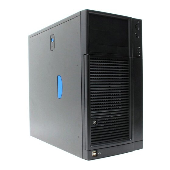
Front View Components TP02345 A. 5.25-in Device Drive Bays B. Front Panel C. Drive Bay Access Door D. Door Lock E. Front Panel USB Ports Figure 2. Front View Components (with Front Bezel Assembly) Intel® Entry Server Chassis SC5299-E DP/WS/BRP User Guide... -
Page 22: Figure 3. Front View Components (Without Front Bezel Assembly)
A. 5.25-in Device Drive Bays B. 3.5-in Device Drive Bay C. Hard Drive Cage D. Drive Bay EMI Shield (shown open) E. Front Panel USB Ports Figure 3. Front View Components (without Front Bezel Assembly) Intel® Entry Server Chassis SC5299-E DP/WS/BRP User Guide... -
Page 23: Internal Components
G. Front Panel USB Ports H. Fixed Hard Drive Cage I. Large Processor Air Duct J. Rear Tool-less PCI Retention Mechanisms K. Fan Duct / System Fan Assembly L. Power Supply Figure 4. Internal Components Intel® Entry Server Chassis SC5299-E DP/WS/BRP User Guide... -
Page 24: Back Panel Components
F. Alternate Serial B port knockout G. PCI Add-in Card slots H. PCI Tool-less Card Retention Mechanisms I. External SCSI knockout J. Serial B port knockout Figure 5. Back Panel Components Intel® Entry Server Chassis SC5299-E DP/WS/BRP User Guide... -
Page 25: Front Panel
Blinking amber indicates a power fault, fan fault, or a non-critical temperature or voltage fault. No light indicates a fatal error during POST. NOTES: 1. LED status may vary depending on server board integrated. Figure 6. Front Panel Components Intel® Entry Server Chassis SC5299-E DP/WS/BRP User Guide... -
Page 26: Peripheral Devices
SCSI, SATA or SAS hard drives) may be purchased to replace the fixed hard drive cage. See Table 3 for order code information. For instructions on installing hard drives, see “Installing and Removing a Fixed Hard Drive”. Intel® Entry Server Chassis SC5299-E DP/WS/BRP User Guide... -
Page 27: Front Bezel Assembly
Entry Server Chassis SC5299-E can be optionally mounted into a rack. Instructions for installing your chassis into a rack are included with the rail kit. The order number for the rack mounting kit is APP3RACKIT. Intel® Entry Server Chassis SC5299-E DP/WS/BRP User Guide... -
Page 28: Mechanical Locks
Table 3. Accessories and Order Codes Accessory Order Code SAS/SATA Hot Swap Drive Bay Upgrade Kit AXX6SASDB SCSI Hot Swap Drive Bay Upgrade Kit AXX6SCSIDB Hot Swap Conversion Kit APP3HSDBKIT Rack Mount Kit APP3RACKIT Intel® Entry Server Chassis SC5299-E DP/WS/BRP User Guide... -
Page 29: Hardware Installations And Upgrades
1. Observe the safety and ESD precautions listed in Appendix A, “Safety Information”. 2. Turn off all peripheral devices connected to the server. Turn off the server. Intel® Entry Server Chassis SC5299-E DP/WS/BRP User Guide... -
Page 30: Installing The Left Side Cover
1. Slide the left side cover on the chassis and latch securely (see letter “A” in the following figure). 2. (Optional) Replace screws (see letter “B”). TP00831 Figure 10. Installing Left Side Cover 3. Reconnect all peripheral devices and the AC power cord. Power up the server. Intel® Entry Server Chassis SC5299-E DP/WS/BRP User Guide... -
Page 31: Removing And Installing The Front Bezel Assembly
Rotate the left side of the front bezel assembly outward slightly (see letter “B”). Disengage the three clips that attach the right side of the front bezel assembly to the chassis and remove (see letter “C”). TP02034 Figure 11. Removing Front Bezel Assembly Intel® Entry Server Chassis SC5299-E DP/WS/BRP User Guide... -
Page 32: Installing The Front Bezel Assembly
Figure 12. Installing the Front Bezel Assembly 2. Reinstall the left side cover. For instructions, see “Installing the Left Side Cover”. 3. Reconnect all peripheral devices and the AC power cable. Power up the server. Intel® Entry Server Chassis SC5299-E DP/WS/BRP User Guide... -
Page 33: Removing And Installing The Processor Air Duct
1. Lower the processor air duct into the chassis and line it up with the two mounting holes in chassis. Secure the processor air duct to the chassis with two mounting screws. Intel® Entry Server Chassis SC5299-E DP/WS/BRP User Guide... -
Page 34: Installing Or Removing A Server Board
Server Board you can install in your chassis will depend upon the model of chassis you purchased. For a breakout of server board/chassis model compatibility, see Table 1, “Breakdown of Intel® Entry Server Chassis SC5299-E Configurations”. To install or remove a server board, do the following: 1. -
Page 35: Figure 15. Removing Drive Cage Emi Shield From Fixed Drive Cage
6. Disconnect cables from any installed fixed hard drives. If necessary, remove hard drives from fixed hard drive cage. For instructions on removing fixed hard drives, see “Removing a Fixed Hard Drive”. Intel® Entry Server Chassis SC5299-E DP/WS/BRP User Guide... -
Page 36: Figure 16. Removing Fixed Hard Drive Cage
9. Remove the PCI card guide by pressing in on the blue tabs (see letter “A” in the following figure) and pulling the PCI card guide outward (see letter “B”). TP01732 Figure 17. Removing PCI Card Guide Intel® Entry Server Chassis SC5299-E DP/WS/BRP User Guide... -
Page 37: Figure 18. Re-Installing Pci Card Guide Into Chassis
“Removing the Processor Air Duct”. ® 11. If installing a server board, refer to your Intel Server Board User’s Guide and/or Quick Start User’s Guide for installation instructions. Use the mounting screws, bumpers and standoffs (if necessary) that came with your chassis to secure the server board to the chassis. -
Page 38: Figure 19. Inserting Fixed Hard Drive Cage Into Chassis
TP02039 Figure 19. Inserting Fixed Hard Drive Cage into Chassis 15. If previously removed, install fixed hard drives and connect power and data cables. For instructions, see “Installing a Fixed Hard Drive”. Intel® Entry Server Chassis SC5299-E DP/WS/BRP User Guide... -
Page 39: Figure 20. Re-Attaching Drive Cage Emi Shield
18. Re-install the left side cover. For instructions, see “Installing the Left Side Cover” 19. Plug all peripheral devices and the AC power cable(s) back into the server. Power up the server. Intel® Entry Server Chassis SC5299-E DP/WS/BRP User Guide... -
Page 40: Installing And Removing A Fixed Hard Drive
Figure 21. Drive Bay Slot Order 1. Observe the safety and ESD precautions listed in Appendix A, “Safety Information”. 2. Power down the server and unplug all peripheral devices and the AC power cable. Intel® Entry Server Chassis SC5299-E DP/WS/BRP User Guide... -
Page 41: Figure 22. Removing Drive Cage Emi Shield From Chassis
5. Loosen thumb screw and remove the drive cage EMI shield (see letter “A” in the following figure). TP01869 Figure 22. Removing Drive Cage EMI Shield from Chassis 6. Remove any PCI add-in boards that use the PCI card guide. For instructions, see “Removing PCI Add-in Boards”. Intel® Entry Server Chassis SC5299-E DP/WS/BRP User Guide... -
Page 42: Figure 23. Removing Pci Card Guide
8. Route the required power cables (connectors P8-P13) from behind the PCI card guide through the cable routing area at the bottom of the fixed drive cage. AF000317 Figure 24. Routing Hard Drive Power Cables Intel® Entry Server Chassis SC5299-E DP/WS/BRP User Guide... -
Page 43: Figure 25. Unlatching Drive Latch
10. Insert fixed hard drive into drive bay and push until it stops. Ensure that the power and data connector end of the hard drive is facing forward AF000319 Figure 26. Inserting Hard Drive into Drive Cage Intel® Entry Server Chassis SC5299-E DP/WS/BRP User Guide... -
Page 44: Figure 27. Latching Drive Latch
12. Install additional drives as necessary. Warning: Drive bay slots 1, 3, and 5 MUST be populated first. Failure to do so could result in thermal issues within the chassis. AF000316 Figure 28. Drive Bay Slot Order Intel® Entry Server Chassis SC5299-E DP/WS/BRP User Guide... -
Page 45: Figure 29. Cabling A Fixed Hard Drive
AF000429 Figure 29. Cabling a Fixed Hard Drive 14. Re-attach the drive cage EMI shield to the chassis and tighten the thumb screw. AF000315 Figure 30. Re-installing Drive Cage EMI Shield Intel® Entry Server Chassis SC5299-E DP/WS/BRP User Guide... -
Page 46: Removing A Fixed Hard Drive
2. Power down the server and unplug all peripheral devices and the AC power cable. 3. Remove the left side cover. For instructions, see “Removing the Left Side Cover”. 4. Remove the front bezel assembly. For instructions, see “Removing and Installing the Front Bezel Assembly”. Intel® Entry Server Chassis SC5299-E DP/WS/BRP User Guide... -
Page 47: Figure 32. Preparing Fixed Hard Drive For Removal
“A” in the following figure). Pull the drive latch forward (see letter “B”) to unlatch the drive locking mechanism for the hard drive you want to remove. AF000430 Figure 32. Preparing Fixed Hard Drive for Removal Intel® Entry Server Chassis SC5299-E DP/WS/BRP User Guide... -
Page 48: Figure 33. Removing Fixed Hard Drive From Drive Bay
Figure 34. Re-installing Drive Cage EMI Shield 9. Re-install the front bezel assembly. For instructions, see “Installing the Front Bezel Assembly” 10. Re-install the left side cover. For instructions, see “Installing the Left Side Cover” Intel® Entry Server Chassis SC5299-E DP/WS/BRP User Guide... -
Page 49: Installing Or Removing A Dvd-Rom Or Cd-Rom Drive
5. Remove the EMI shield from the 5.25-in device drive bay (see letter “A” in the following figure). Move latch to the “unlock” position (see letter “B”). TP01063 Figure 35. Removing 5.25-in Drive EMI Shield Intel® Entry Server Chassis SC5299-E DP/WS/BRP User Guide... -
Page 50: Figure 36. Installing Cd-Rom Or Dvd-Rom Drive
P4 connector from the power supply) and data cables to the rear of the CD-ROM or DVD-ROM drive (see letter “F”). TP01064 Figure 36. Installing CD-ROM or DVD-ROM Drive 7. If necessary, remove the filler panel from the front bezel assembly. TP01723 Intel® Entry Server Chassis SC5299-E DP/WS/BRP User Guide... -
Page 51: Removing A Cd-Rom Or Dvd-Rom Drive
(see letter “A” in the following figure). Move latch to the “unlock” position (see letter “B”). Slide CD-ROM or DVD-ROM drive out of the Device Drive Bay (see letter “C”). TP02047 Figure 37. Removing CD-ROM or DVD-ROM Drive Intel® Entry Server Chassis SC5299-E DP/WS/BRP User Guide... -
Page 52: Installing The Removing Pci Add-In Boards
Note: You may want to install an operating system before installing any PCI add-in boards. 1. Observe the safety and ESD precautions listed in Appendix A, “Safety Information”. 2. Power down the server and unplug all peripheral devices and the AC power cable. Intel® Entry Server Chassis SC5299-E DP/WS/BRP User Guide... -
Page 53: Figure 39. Opening Pci Add-In Card Retention Device
Place board on an anti-static surface. Record the type and serial number of the add-in board in your equipment log. Set jumpers or switches on the board according to the manufacturer’s instructions. Intel® Entry Server Chassis SC5299-E DP/WS/BRP User Guide... -
Page 54: Removing Pci Add-In Boards
Appendix A, “Safety Information”. 2. Power down the server and unplug all peripheral devices and the AC power cable. 3. Remove the left side cover. For instructions, see “Removing the Left Side Cover”. Intel® Entry Server Chassis SC5299-E DP/WS/BRP User Guide... -
Page 55: Figure 42. Opening Pci Add-In Card Retention Device
(see letter “A” in the following figure). Place the removed add-in board in an anti-static protective wrapper. Close the back panel PCI Add-in Card Retention Device (see letter “B”). TP01724 Figure 43. Removing PCI Add-in Board Intel® Entry Server Chassis SC5299-E DP/WS/BRP User Guide... -
Page 56: Replacing The Front Panel Board
3. Remove the left side cover. For instructions, see “Removing the Left Side Cover” 4. Remove the front bezel assembly if it is installed. For instructions, see “Removing the Front Bezel Assembly”. Intel® Entry Server Chassis SC5299-E DP/WS/BRP User Guide... -
Page 57: Figure 45. Removing Right Side Cover From Chassis
Lift the right side cover off the chassis. TP01736 Figure 45. Removing Right Side Cover from Chassis 6. Remove the three screws securing the front panel board to the chassis. TP01737 Figure 46. Unattaching Front Panel Board from Chassis Intel® Entry Server Chassis SC5299-E DP/WS/BRP User Guide... -
Page 58: Figure 47. Removing Front Panel Board From Chassis
“B”) and the chassis intrusion cable (see letter “C”) from the front panel board. AF000432 Figure 47. Removing Front Panel Board from Chassis 8. Remove standoffs from old front panel and install on new front panel. TP02000 Figure 48. Removing Standoffs from Front Panel Intel® Entry Server Chassis SC5299-E DP/WS/BRP User Guide... -
Page 59: Figure 49. Installing Front Panel Board In Chassis
10. Use one hand to align the front panel board in position inside the chassis. With your other hand, tighten the three screws to secure the front panel board to the front of the chassis. TP01740 Figure 50. Positioning Front Panel Board in Chassis Intel® Entry Server Chassis SC5299-E DP/WS/BRP User Guide... -
Page 60: Replacing A System Fan
Appendix A, “Safety Information”. 2. Power down the server and unplug all peripheral devices and the AC power cable. 3. Remove the left side cover. For instructions, see “Removing the Left Side Cover”. Intel® Entry Server Chassis SC5299-E DP/WS/BRP User Guide... -
Page 61: Figure 52. Removing Fan Duct / System Fan Assembly
4. Remove the fan duct /system fan assembly. AF000284 Figure 52. Removing Fan Duct / System Fan Assembly 5. Re-install the fan duct / system fan assembly. TP01853 Figure 53. Re-installing Fan Duct / System Fan Assembly Intel® Entry Server Chassis SC5299-E DP/WS/BRP User Guide... -
Page 62: Replacing A Fixed Power Supply
® Caution: The fixed power supply is NOT hot swappable in the DP and WS models of the Intel Entry Server Chassis SC5299-E. Before removing or replacing the fixed power supply,... -
Page 63: Figure 55. Removing Fixed Power Supply From Chassis
Make sure that the new fixed power supply rests on the small metal shelf on the side wall of the chassis (see letter “A” in the following figure). TP01753 Figure 56. Inserting Fixed Power Supply in Chassis Intel® Entry Server Chassis SC5299-E DP/WS/BRP User Guide... -
Page 64: Figure 57. Locking Fixed Power Supply Into Chassis
Figure 57. Locking Fixed Power Supply into Chassis ® 9. Route and connect the P1, P2, and P14 cables to the server board. Refer to the Intel ® Server Board Quick Start User’s Guide or User Guide that came with your Intel server board for appropriate power connections. -
Page 65: Installing An Additional Hot Swap Power Supply Module (Brp Configuration Only)
2. Insert finger into hole in middle of filler panel and remove filler panel from chassis. TP00916 Figure 58. Removing Power Supply Filler Panel 3. Insert new hot swap power supply module until it clicks into place. TP00917 Figure 59. Inserting Additional Hot Swap Power Supply Module Intel® Entry Server Chassis SC5299-E DP/WS/BRP User Guide... -
Page 66: Replacing A Hot Swap Power Supply (Brp Configuration Only)
Figure 60. Removing Hot Swap Power Supply Module from Chassis 4. Insert new hot swap power supply module. TP00854 Figure 61. Inserting Hot Swap Power Supply Module in Chassis 5. Connect power cable to replaced hot swap power supply. Intel® Entry Server Chassis SC5299-E DP/WS/BRP User Guide... -
Page 67: Replacing A Hot Swap Power Supply Cage (Brp Configuration Only)
Figure 62. Removing Hot Swap Power Supply Module 5. Remove second (redundant) hot swap power supply module (or filler panel), if one is present. 6. Disconnect all internal power cables from chassis components and server board. Intel® Entry Server Chassis SC5299-E DP/WS/BRP User Guide... -
Page 68: Figure 63. Detaching Hot Swap Power Supply Cage From Inside Of Chassis
Note: You may have to work the power cables through slot sopenings with your free hand as you remove the power supply cage from the chassis. TP01762 Figure 64. Detaching Hot Swap Power Supply Cage from Rear of Chassis Intel® Entry Server Chassis SC5299-E DP/WS/BRP User Guide... -
Page 69: Figure 65. Removing Rear Support Bracket From Hot Swap Power Supply Cage
10. Attach the rear support bracket to the new power supply cage with the two screws removed from the previous step. TP01763 Figure 66. Attaching Rear Support Bracket to Power Supply Cage Intel® Entry Server Chassis SC5299-E DP/WS/BRP User Guide... -
Page 70: Figure 67. Securing Hot Swap Power Supply Cage To Rear Of Chassis
Figure 67. Securing Hot Swap Power Supply Cage to Rear of Chassis 12. Secure inside panel of hot swap power supply cage to chassis with two screws. TP01767 Figure 68. Securing Hot Swap Power Supply Cage to Inside of Chassis Intel® Entry Server Chassis SC5299-E DP/WS/BRP User Guide... -
Page 71: Figure 69. Re-Installing Hot Swap Power Supply Module(S)
Figure 69. Re-installing Hot Swap Power Supply Module(s) 18. Install the left side cover. For instructions, see “Installing the Left Side Cover”. 19. Reconnect all peripheral devices and the AC power cable(s) to the server. Power up the server. Intel® Entry Server Chassis SC5299-E DP/WS/BRP User Guide... -
Page 72: Installing Feet For A Pedestal-Configured Chassis
Hardware Installations and Upgrades Installing Feet for a Pedestal-configured Chassis ® Note: Do not install feet on your Intel Entry Server Chassis SC5299-E if it is to be installed in a rack. Only install feet on a pedestal-configured chassis. 1. Observe the safety and ESD precautions listed in Appendix A, “Safety... -
Page 73: Hot Swap Drive Cage Upgrade Install Instructions (Optional)
The fixed hard drive cage that ships with your Intel Entry Server Chassis SC5299-E is upgradeable to a hot swap drive cage with a SCSI or SAS/SATA backplane. See your Intel Representative for ordering information. Up to six hot swap hard drives can be installed in the optional hot swap drive cage. Power requirements for each individual hard drive may limit the maximum number of drives that can be integrated into the server chassis. -
Page 74: Installing A Hot Swap Hard Drive Cage With A Sas/Sata Or Scsi Backplane
Figure 71. Removing Fixed Drive Cage EMI Shield from Chassis 6. Disconnect cables from any fixed hard drives and remove hard drives from fixed hard drive cage. For instructions on removing fixed hard drives, see “Removing a Fixed Hard Drive”. Intel® Entry Server Chassis SC5299-E DP/WS/BRP User Guide... -
Page 75: Figure 72. Removing Fixed Hard Drive Cage From Chassis
8. Gather together the components for the hot swap drive cage installation. You should have a hot swap drive cage with either a SAS/SATA or SCSI backplane, a side filler panel, a latch plate, a fan bracket, and a fan. Intel® Entry Server Chassis SC5299-E DP/WS/BRP User Guide... -
Page 76: Figure 73. Removing Stud Screws From Hot Swap Drive Cage
Figure 73. Removing Stud Screws from Hot Swap Drive Cage 10. Attach the latch plate to the left side of the hot swap drive cage. TP01060 Figure 74. Attaching Latch Plate to Hot Swap Drive Cage Intel® Entry Server Chassis SC5299-E DP/WS/BRP User Guide... -
Page 77: Figure 75. Attaching Filler Panel To Hot Swap Drive Cage
Figure 75. Attaching Filler Panel to Hot Swap Drive Cage 12. Remove the two thumb screws that secure the backplane to the hot swap drive cage. TP01716 Figure 76. Removing Thumb Screws from Backplane Intel® Entry Server Chassis SC5299-E DP/WS/BRP User Guide... -
Page 78: Figure 77. Attaching Fan Bracket To Hot Swap Drive Cage (Sas/Sata Drive Cage Illustrated)
The backplane may have slipped once the thumb screws were removed. Ensure that the backplane is positioned correctly before re-tightening the thumb screws. TP01061 Figure 77. Attaching Fan Bracket to Hot Swap Drive Cage (SAS/SATA drive cage illustrated) Intel® Entry Server Chassis SC5299-E DP/WS/BRP User Guide... -
Page 79: Figure 78. Attaching Fan To Fan Bracket
Press the fan into the fan bracket until is clicks into place. Caution: Ensure that the label and directional airflow arrow on fan are pointed out (away from the backplane). TP01062 Figure 78. Attaching Fan to Fan Bracket Intel® Entry Server Chassis SC5299-E DP/WS/BRP User Guide... -
Page 80: Figure 79. Inserting Hot Swap Drive Cage Into Chassis
Figure 79. Inserting Hot Swap Drive Cage into Chassis 16. Connect fan cable to the appropriate connector on the server board. See your server board documentation for information on the location of the fan cable connector. Intel® Entry Server Chassis SC5299-E DP/WS/BRP User Guide... -
Page 81: Figure 80. Cabling The Scsi Hot Swap Drive Cage
(Optional, dependent on server board installed) Connect the IPMB header (see letter “C”) to the IPMB connector on the SCSI backplane. iv. Connect the fan power to the server board. For the Intel® Server Board S5000VSA, use FAN1. For other Intel® server boards, refer to the Quick Start User’s Guide that came with the server board. -
Page 82: Figure 81. Layout Of Cable Connectors On The Sas/Sata Backplane (Backplane Without Expander Shown)
HDD 2 HDD 5 HDD 0 HDD 4 AF00450 Power cable Data Cable IPMB SES (not available in AXX6DRV3GEXP) Figure 81. Layout of Cable Connectors on the SAS/SATA Backplane (Backplane without expander shown) Intel® Entry Server Chassis SC5299-E DP/WS/BRP User Guide... -
Page 83: Figure 82. Making Six-Drive Sas/Sata Hot-Swap Drive Cage Backplane Without Expander Connections (Fan Bracket Not Shown In The Illustration For Clarity)
Connect the IPMB cable (see letter “C”). iv. Connect the SES cable (see letter “D”). v. Connect the fan power to the server board. For the Intel® Server Board S5000VSA, use FAN1. For other Intel® server boards, refer to the Quick Start User’s Guide that came with the server board. -
Page 84: Figure 83. Making Six-Drive Hot Swap Drive Cage Backplane With Expander Connections (Fan Bracket Not Shown In The Illustration For Clarity)
SATA connector on the SAS/SATA backplane. iii. Connect the IPMB cable (see letter “C”). iv. Connect the fan power to the server board. For the Intel® Server Board S5000VSA, use FAN1. For other Intel® server boards, refer to the Quick Start User’s Guide that came with the server board. -
Page 85: Installing A Hot Swap Hard Drive
Entry Server Chassis SC5299-E does not support all hard drives. See “Additional Information and Software”for an Internet link to a list of supported hard drives. 1. Open the drive bay access door. AF000311 Figure 84. Opening Drive Bay Access Door Intel® Entry Server Chassis SC5299-E DP/WS/BRP User Guide... -
Page 86: Figure 85. Releasing Drive Carrier From Hot Swap Drive Cage
5. Set any jumpers and/or switches on the drive according to the drive manufacturer's instructions. 6. With the drive circuit-side down, position the connector end of the drive so that it is facing the rear of the drive carrier. Intel® Entry Server Chassis SC5299-E DP/WS/BRP User Guide... -
Page 87: Figure 87. Installing Hard Drive Into Drive Carrier
Once the black drive carrier lever begins to close by itself, push on it to lock the drive carrier into place. AF000313 Figure 88. Re-installing Drive Carrier in Hot Swap Drive Cage Intel® Entry Server Chassis SC5299-E DP/WS/BRP User Guide... -
Page 88: Figure 89. Closing Drive Bay Access Door
9. Close the drive bay access door. AF000314 Figure 89. Closing Drive Bay Access Door Removing a Hot-swap Hard Drive 1. Open the drive bay access door. AF000311 Figure 90. Opening Drive Bay Access Door Intel® Entry Server Chassis SC5299-E DP/WS/BRP User Guide... -
Page 89: Figure 91. Removing Drive Carrier From Hot Swap Drive Cage
3. Remove the four screws that attach the hard drive to the drive carrier. Lift the drive from the carrier. Store the old drive in an anti-static bag. TP01714 Figure 92. Removing Hard Drive from Drive Carrier Intel® Entry Server Chassis SC5299-E DP/WS/BRP User Guide... -
Page 90: Figure 93. Installing Hard Drive In Drive Carrier
The green latch must be to the left. Do not push on the black lever until the lever begins to close by itself. When the black lever begins to close by itself, push on it to lock the drive carrier into place. Intel® Entry Server Chassis SC5299-E DP/WS/BRP User Guide... -
Page 91: Figure 95. Re-Installing Drive Carrier In Hot Swap Drive Cage
Note: For proper airflow, the drive carrier must be replaced in the chassis, even if no hard drive is installed in it. AF000313 Figure 95. Re-installing Drive Carrier in Hot Swap Drive Cage 6. Close the drive bay access door. AF000314 Figure 96. Closing Drive Bay Access Door Intel® Entry Server Chassis SC5299-E DP/WS/BRP User Guide... - Page 92 Hot Swap Drive Cage Upgrade Install Instructions (optional) Intel® Entry Server Chassis SC5299-E DP/WS/BRP User Guide...
-
Page 93: Rack Mount Kit Install Instructions (Optional)
1. Observe the safety and ESD precautions listed in Appendix A, “Safety Information”. 2. Power down the server and unplug all peripheral devices and the AC power cable. 3. Lay the chassis down on its right side. Intel® Entry Server Chassis SC5299-E DP/WS/BRP User Guide... -
Page 94: Figure 97. Removing Chassis Feet
5. Remove the top side cover by pressing the latch and pushing back on the side cover to slide rearward and lift from chassis. TP00958 Figure 98. Removing Top Side Cover from Chassis Intel® Entry Server Chassis SC5299-E DP/WS/BRP User Guide... -
Page 95: Figure 99. Removing Pci Card Guide
6. Remove any PCI add-in boards. Remove the PCI card guide by pressing in on the blue tabs (see letter “A” in the following figure) and pulling the PCI card guide outward (see letter “B”). TP02001 Figure 99. Removing PCI Card Guide Intel® Entry Server Chassis SC5299-E DP/WS/BRP User Guide... -
Page 96: Figure 100. Removing Plastic Filler Panel From Chassis
7. Remove plastic filler panel from chassis by pushing on interior tab (see letter “A” in the following figure) and sliding filler panel towards rear of chassis (see letter “B”). AF000285 Figure 100. Removing Plastic Filler Panel from Chassis Intel® Entry Server Chassis SC5299-E DP/WS/BRP User Guide... -
Page 97: Figure 101. Removing Plastic Plugs
8. Remove the three plastic plugs from left side of chassis. AF000286 Figure 101. Removing Plastic Plugs 9. Remove two screws from left and right sides of chassis. AF000287 Figure 102. Removing Rear Screws Intel® Entry Server Chassis SC5299-E DP/WS/BRP User Guide... -
Page 98: Figure 103. Removing Plastic Plugs From Top Side Cover
TP02004 Figure 103. Removing Plastic Plugs from Top Side Cover 11. Install rack handle on left side cover using four 6-32 screws. TP01053 Figure 104. Installing Rack Handle on Left Side Cover Intel® Entry Server Chassis SC5299-E DP/WS/BRP User Guide... -
Page 99: Figure 105. Affixing Label To Front Panel
13. Install top side cover on chassis. Warning: This chassis must be operated with the left side cover installed to ensure proper cooling. TP01057 Figure 106. Installing Top Side Cover on Chassis Intel® Entry Server Chassis SC5299-E DP/WS/BRP User Guide... -
Page 100: Figure 107. Detaching Inner Rack Rail From Rack Rail Assembly
14. Detach inner rack rail from rack rail assembly. Press tab on inside of rack rail to release rack rail from rack rail assembly. TP02006 Figure 107. Detaching Inner Rack Rail from Rack Rail Assembly Intel® Entry Server Chassis SC5299-E DP/WS/BRP User Guide... -
Page 101: Figure 108. Attaching Inner Rack Rails To Chassis
16. Attach outer rack rails to rack uprights. Ensure that the screws (two per outer rack rail; see letter “A” in the following figure) pass through the rack upright (see letter “B”), and the outer rack rail (see letter “C”). Intel® Entry Server Chassis SC5299-E DP/WS/BRP User Guide... -
Page 102: Figure 109. Attaching Outer Rack Rails To Rack Uprights
Rack Mount Kit Install Instructions (optional) TP01056 Figure 109. Attaching Outer Rack Rails to Rack Uprights Intel® Entry Server Chassis SC5299-E DP/WS/BRP User Guide... -
Page 103: Figure 110. Installing Chassis Into Rack
WARNING: Safe handling of this system requires TWO people. TP01058 Figure 110. Installing Chassis into Rack 18. Reconnect all peripheral devices and the AC power cable to the server. Power up the server. Intel® Entry Server Chassis SC5299-E DP/WS/BRP User Guide... - Page 104 Rack Mount Kit Install Instructions (optional) Intel® Entry Server Chassis SC5299-E DP/WS/BRP User Guide...
-
Page 105: Technical Reference
Table 4. 550-W Power Supply Output Capability Maximum Voltage Current +3.3 V 24 A +5.0 V 24 A +5 V Standby +12.0 V1 40 A -12.0 V 0.5 A +12 V2 16 A Intel® Entry Server Chassis SC5299-E DP/WS/BRP User Guide... -
Page 106: 670-W Single Power Supply Input Voltages
Maximum Voltage Current +3.3 V 24 A +5.0 V 30 A +5 V Standby 3.0 A -12.0 V 0.3 A 12 V1 16 A 12 V2 16 A 12 V3 16 A Intel® Entry Server Chassis SC5299-E DP/WS/BRP User Guide... -
Page 107: System Environmental Specifications
DP, BRP configurations - 5.5 BA LWA idle; 6.0 BA LWA typical operation WS configuration - 4.8 BA LWA idle; 5.5 BA LWA typical operation Electrostatic Tested to 15 kilovolts (kV); no component damage. discharge (ESD) Intel® Entry Server Chassis SC5299-E DP/WS/BRP User Guide... - Page 108 Technical Reference Intel® Entry Server Chassis SC5299-E DP/WS/BRP User Guide...
-
Page 109: Safety Information
To reduce the risk of bodily injury, electrical shock, fire, and equipment damage, read this document and observe all warnings and precautions in ® this guide before installing or maintaining your Intel server product. In the event of a conflict between the information in this document and information provided with the product or on the website for a particular product, the product documentation takes precedence. -
Page 110: Intended Application Uses
To remove power from system, you must unplug the AC power cord from the wall outlet. Your system may use more than one AC power cord. Make sure all AC power cords are Intel® Entry Server Chassis SC5299-E DP/WS/BRP User Guide... -
Page 111: System Access Warnings
Turn off all peripheral devices connected to this product. • Turn off the system by pressing the power button to off. • Disconnect the AC power by unplugging all AC power cords from the system or wall outlet. Intel® Entry Server Chassis SC5299-E DP/WS/BRP User Guide... -
Page 112: Rack Mount Warnings
Always handle boards carefully. They can be extremely sensitive to ESD. Hold boards only by their edges. After removing a board from its protective wrapper or from the server, place the board component side up on a grounded, static free surface. Use a Intel® Entry Server Chassis SC5299-E DP/WS/BRP User Guide... -
Page 113: Other Hazards
Caution: To avoid risk of radiation exposure and/or personal injury: • Do not open the enclosure of any laser peripheral or device • Laser peripherals or devices have are not user serviceable • Return to manufacturer for servicing Intel® Entry Server Chassis SC5299-E DP/WS/BRP User Guide... -
Page 114: Deutsch
Safety Information Deutsch Sicherheitshinweise für den Server Das vorliegende Dokument bezieht sich auf Intel® Serverplatinen, Intel® Servergehäuse (Standfuß und Rack) sowie installierte Peripheriegeräte. Es enthält Warnungen und Vorsichtsmaßnahmen zur Vermeidung von Gefahren durch Verletzung, Stromschlag, Feuer und Beschädigungen von Geräten. Lesen Sie diese Dokument daher sorgfältig, bevor Sie Ihr Intel®... -
Page 115: Zielbenutzer Der Anwendung
Verwenden Sie mechanische oder andere geeignete Hilfsmittel zum Transportieren oder Anheben von Geräten. • Entfernen Sie alle Komponenten, die sich leicht abnehmen lassen, um das Gewicht zu reduzieren und die Handhabung zu erleichtern. Intel® Entry Server Chassis SC5299-E DP/WS/BRP User Guide... -
Page 116: Warnungen Zu Netzspannung Und Elektrizität
Typ entspricht. Jedes Netzteil im System muß über ein eigenes Netzkabel angeschlossen werden. Einige Netzteile von Intel Servern verwenden Nullleitersicherungen. Vorsicht ist geboten im Umgang mit Netzteilen, welche Nullleitersicherungen verwenden, um das Risiko eines elektrischen Schlages zu vermeiden Das Netzteil in diesem Produkt enthält keine Teile, die vom Benutzer gewartet werden... -
Page 117: Warnhinweise Für Den Systemzugang
Einbauen von Hot-Plug-Komponenten sorgfältig vor, um nicht mit heißen Komponenten in Berührung zu kommen. Vorsicht: Berühren Sie nicht die rotierenden Lüfterflügel, um Verletzungen zu vermeiden. Falls Ihr System mit eine Lüfterabdeckung besitzt, darf es nicht ohne diese Abdeckung betrieben werden. Intel® Entry Server Chassis SC5299-E DP/WS/BRP User Guide... -
Page 118: Warnhinweise Für Racks
Ausbau aus dem Server mit der Bauelementseite nach oben auf eine geerdete, statisch entladene Unterlage.Verwenden Sie dazu, sofern verfügbar, eine leitfahige Schaumstoffunterlage, aber niche die Schutzhülle der Platine. Ziehen Sie die Platine nicht über eine Fläche. Intel® Entry Server Chassis SC5299-E DP/WS/BRP User Guide... -
Page 119: Andere Gefahren
Öffnen Sie keinesfalls das Gehäuse von Laser-Peripheriegeräten oder Laser- Komponenten. • Laser-Peripheriegeräte oder -Komponenten besitzen keine für den Benutzer wartungsbedürftigen Teile. • Schicken Sie das Gerät für Wartungsarbeiten an den Hersteller zurück. Intel® Entry Server Chassis SC5299-E DP/WS/BRP User Guide... -
Page 120: Français
Français Consignes de sécurité sur le serveur Ce document s’applique aux cartes serveur Intel®, au châssis de serveur Intel® (sur pieds et sur rack) et aux périphériques installés. Pour réduire les risques de dommages corporels, d’électrocution, d’incendie et de dommages matériels, lisez ce document et respectez tous les avertissements et précautions mentionnés dans ce guide avant... -
Page 121: Domaines D'utilisation Prévus
• Utilisez l’assistance mécanique ou toute autre assistance appropriée lorsque vous déplacez et soulevez le matériel. • Pour réduire le poids en vue de faciliter la manipulation, retirez tout composant amovible. Intel® Entry Server Chassis SC5299-E DP/WS/BRP User Guide... -
Page 122: Alimentation Et Avertissements En Matière D'électricité
Vous devez les débrancher avant d’ouvrir le châssis, d’ajouter ou de supprimer un composant non connectable à chaud. Les alimentations de certains serveurs Intel sont munies de doubles fusibles pôle/neutre: veuillez observer les précautions d'usage afin d'éviter tout risque d'eléctrocution. -
Page 123: Avertissements Sur L'accès Au Système
Attention: Pour éviter de vous blesser, ne touchez pas les pales de ventilateur en mouvement. Si votre système est fourni avec une protection sur le ventilateur, ne mettez pas le système en route sans la protection en place. Intel® Entry Server Chassis SC5299-E DP/WS/BRP User Guide... -
Page 124: Avertissements Sur Le Montage En Rack
Utilisez si possible un tapi de mousse conducteru, mais pas l’emballage de la carte. Veillez à ce que la carte ne glisse sur aucune surface. Intel® Entry Server Chassis SC5299-E DP/WS/BRP User Guide... -
Page 125: Autres Risques
Attention: Pour éviter tout risque d’exposition aux rayonnements et/ou de dommage personnel: • N’ouvrez pas l’enceinte d’un périphérique laser. • Les périphériques laser ne sont pas réparables par l’utilisateur. • Retournez-les au fabricant en cas de problème. Intel® Entry Server Chassis SC5299-E DP/WS/BRP User Guide... -
Page 126: Español
Safety Information Español Información de seguridad del servidor ® Este documento se aplica a las tarjetas de servidor de Intel , las carcasas de servidor de ® Intel (montaje en bastidor y en pedestal) y los dispositivos periféricos. Para reducir el riesgo de daños corporales, descargas eléctricas, fuego y en el equipo, lea este documento... -
Page 127: Aplicaciones Y Usos Previstos
Utilice medios mecánicos u otros que sean adecuados al trasladar o levantar el equipo. • Para que el peso sea menor para manipularlo con más facilidad, extraiga los componentes que sean de fácil extracción. Intel® Entry Server Chassis SC5299-E DP/WS/BRP User Guide... -
Page 128: Advertencias De Alimentación Y Eléctricas
CA estén desenchufado antes de abrir la carcasa, agregar o extraer cualquier componente que no es de conexión en funcionamiento. Algunas fuentes de alimentación de electricidad de los servidores de Intel utilizan el polo neutral del fuselaje. Para evitar riesgos de choques electricos use precauciónes al trabajar con las fuentes de alimentación que utilizan el polo neutral de fuselaje. -
Page 129: Advertencias El Acceso Al Sistema
Precaución: Para evitar posibles daños, no toque las aspas en movimiento de los ventiladores. Si el sistema se le ha suministrado con una protección para el ventilador, asegúrese de que cuando esté funcionando el sistema la protección esté en su sitio. Intel® Entry Server Chassis SC5299-E DP/WS/BRP User Guide... -
Page 130: Advertencias Sobre El Montaje En Bastidor
Utilice una almohadilla de espuma conductora si dispone de ella, pero nunca el envoltorio de la tarjeta. No deslice la tarjeta sobre ninguna superficie. Intel® Entry Server Chassis SC5299-E DP/WS/BRP User Guide... - Page 131 Precaución: Para evitar el riesgo de la exposición a radiaciones o de daños personales: • No abra la caja de ningún periférico o dispositivo láser • Los periféricos o dispositivos láser no pueden ser reparados por el usuario • Haga que el fabricante los repare. Intel® Entry Server Chassis SC5299-E DP/WS/BRP User Guide...
- Page 132 为避免人身伤害与财产损失,安装本产品之前,请阅读以下所有安全指导和信息。 下面所列的安全符号可能在整个文档中使用并可能标注于产品和 / 或产品包装之上。 注意 表示如果无视此“? ? ? 项”? ? ? ? ? ? ? 轻微人身伤害或财产损失的危险。 警告 表示如果无视此“? ? ”? ? ? ? ? ? ? 严重人身伤害的危险。 表示如果无视所示信息,即存在潜在的危险。 表示如果不遵守安全指导,存在可导致严重伤害或死亡的电击危险。 表示灼热组件或表面。 表示请勿触摸风机叶片,否则可能致伤。 表示拔下所有交流电线,断开交流电源 Intel® Entry Server Chassis SC5299-E DP/WS/BRP User Guide...
- Page 133 远离振动源或物理震动。 • 与电气设备产生的强大电磁场隔离。 • 在易受闪电袭击的地区,我们建议将系统插入电涌抑制器并在闪电期间断开通信 线路与调制解调器之间的连接。 • 提供正确接地的墙壁插座。 • 提供足够的空间,以便拿取电源供应线,因为这是本产品的主要电源断开器。 设备操作规范 减少人身伤害或设备受损的危险: • 移举设备时遵守当地的职业健康与安全要求。 • 借助机械手段或其他合适的手段移举设备。 • 拆除一切易分离组件,以降低重量并方便操作。 电源与电气警告 注意事项 电源按钮(如待机电源标记所示)并不能完全关闭系统的交流电源,只要系统已接 通电源,就存在 5V 待机电源。要从系统切断电源,须从墙壁电源插座中拔下交流电线。您的系统可能 不止使用一根交流电线。请确保所有的交流电线都已拔下。打开机箱或增加或去除 任何热插拔组件之前,确保交流电线已拔下。 若非所需的确切类型,请勿尝试修改或使用交流电线。系统的每个电源供应设备都 需要一根单独的交流电线。 本产品的电源供应设备包含非用户维修部件。请勿打开电源供应设备。电源供应设 备包含非常危险的电压级、电流级和能量级。请与生产商联系维修事宜。 替换热插拔电源供应设备时,请先拔下需替换的电源供应设备上的电源线,再将其 从服务器上移除。 Intel® Entry Server Chassis SC5299-E DP/WS/BRP User Guide...
- Page 134 ⎯ 电源线须拥有适合插座的安全接地插头或触点。 • 电源线为交流电源的主要断开设备。插座须靠近设备并可随时断开。 • 电源线须插入所提供的拥有合适接地的插座。 系统使用警告 注意事项 为避免人身伤害或财产损失,无论何时检查产品内部,以下安全指导都适用: • 关闭所有与本产品相连的外设。 • 按下电源按钮至关闭状态,关闭系统。 • 从系统或墙壁插座上拔下所有交流电线,断开交流电源。 • 断开与系统相连的所有线缆和通信线路。 • 卸除舱口盖时,保留所有螺钉及其他紧固件。完成产品内部检查之后,请 用螺钉或紧固件重新固定舱口盖。 • 请勿打开电源供应设备。电源供应设备内没有可维修部件。请与生产商联系 维修事宜. • 增加或替换任何非热插拔组件之前,请关闭服务器电源并断开所有电源线 。 • 替换热插拔电源供应设备时,请先拔下需替换的电源供应设备上的电源线 ,然后再从服务器上移除电源供应设备。 注意事项 如果服务器一直在运行,任何已安装的处理器和吸热设备都可能很热。除非要增加 或移除热插拔组件,否则请待系统冷却后再开盖。为避免在热插拔组件安装过程中 接触灼热组件,移除或安装热插拔组件时务须小心。 Intel® Entry Server Chassis SC5299-E DP/WS/BRP User Guide...
- Page 135 Safety Information 注意事项 为避免受伤,请勿触摸运转的风机叶片。如果系统的风机上配有防护装置,请勿卸 下风机防护装置运行系统。 机架固定件警告 设备的机架须固定在稳固的支座上,以防从中安装服务器或设备时倒塌。须按照机 架生产商提供的安装说明进行安装。 从下往上将设备安装在机架上,最重的设备安装在机架的最底层。 一次只从机架上安装一件设备。 您须负责安装整个机架装置的主要电源断开设备。此主要断开设备须随时可用,且 须标明为控制整个装置(而不仅限于服务器)的电源。 为避免潜在的电击危险,须对机架及其上所安装的每一件设备实行正确的安全接地 。 静电放电 (ESD) 注意事项 ESD 会损坏磁盘驱动器、主板及其他部件。我们建议您执行 ESD 工作站的所有步骤。如果没有 ESD 工作站,则采取一些静电放电保护措施,操作部件时,戴上与服务器上的机箱接地 或任何未喷漆金属表面连接的防静电腕带。 操作主板时始终保持小心。它们可能对 ESD 非常敏感。拿持主板时只接触边缘。从保护包装中或从服务器上取出主板后,请将 主板组件侧面朝上放置在无静电的接地表面上。请使用导电泡沫垫(若有),不要 使用主板包装。请勿将主板在任何表面上滑动。 Intel® Entry Server Chassis SC5299-E DP/WS/BRP User Guide...
- Page 136 Safety Information 其他危险 替换电池 注意事项 不正确替换电池可能导致爆炸危险。替换电池时,请只使用设备生产商推荐使用的 电池。 请按当地法规处置电池。 请勿对电池充电。 请勿拆卸、刺穿或以其他方式损坏电池。 冷却和气流 注意事项 按照说明小心布置线缆,尽量减少气流阻塞和冷却问题。 为保证适当的冷却和气流,运行系统时请确保机箱盖已安装。未安装机箱盖即运行 系统可能导致系统部件受损。安装机箱盖的步骤如下: 首先检查并确保系统内没有遗留的未固定工具或部件。 • 检查线缆、内插板和其他组件已正确安装。 • 按产品说明安装机箱盖。 • 激光外设或激光设备 注意事项 为避免幅射暴露和 / 或人身伤害: 请勿打开任何激光外设或激光设备的外壳 • 激光外设或激光设备为非用户维修设备 • 请与生产商联系维修事宜 Intel® Entry Server Chassis SC5299-E DP/WS/BRP User Guide...
-
Page 137: Installation/Assembly Safety Instructions
To do this: 1. Unlock and remove the padlock from the back of the system if a padlock has been installed. 2. Remove and save all screws from the covers. 3. Remove the cover(s). Intel® Entry Server Chassis SC5299-E DP/WS/BRP User Guide... - Page 138 • Provided with a properly grounded wall outlet. • Provided with sufficient space to access the power supply cord(s), because they serve as the product's main power disconnect. Intel® Entry Server Chassis SC5299-E DP/WS/BRP User Guide...
-
Page 139: Deutsch
5. Tragen Sie ein geerdetes Antistatik Gelenkband, um elektrostatische Ladungen (ESD) über blanke Metallstellen bei der Handhabung der Komponenten zu vermeiden. 6. Schalten Sie das System niemals ohne ordnungsgemäß montiertes Gehäuse ein. Intel® Entry Server Chassis SC5299-E DP/WS/BRP User Guide... - Page 140 Bei falschem Einsetzen einer neuen Batterie besteht Explosionsgefahr. Die Batterie darf nur durch denselben oder einen entsprechenden, vom Hersteller empfohlenen Batterietyp ersetzt werden. Entsorgen Sie verbrauchte Batterien den Anweisungen des Herstellers entsprechend. Intel® Entry Server Chassis SC5299-E DP/WS/BRP User Guide...
- Page 141 Telekommunikationsleitungen mit dem Modem bestehen; • "mit einer geerdeten Wechselstromsteckdose ausgerüstet sein; • "über ausreichend Platz verfügen, um Zugang zu den Netzkabeln zu gewährleisten, da der Stromanschluß des Produkts hauptsächlich über die Kabel unterbrochen wird Intel® Entry Server Chassis SC5299-E DP/WS/BRP User Guide...
-
Page 142: Français
1. Si un cadenas a été installé sur à l'arrière du système, déverrouillez-le et retirez-le. 2. Retirez toutes les vis des panneaux et mettez-les dans un endroit sûr. 3. Retirez les panneaux. Intel® Entry Server Chassis SC5299-E DP/WS/BRP User Guide... - Page 143 • "Muni d'une prise murale correctement mise à la terre. • "Suffisamment spacieux pour vous permettre d'accéder aux câbles d'alimentation (ceux-ci étant le seul moyen de mettre le système hors tension). Intel® Entry Server Chassis SC5299-E DP/WS/BRP User Guide...
-
Page 144: Español
Para ello: 1. Desbloquee y extraiga el bloqueo de seguridad de la parte posterior del sistema, si se ha instalado uno. 2. Extraiga y guarde todos los tornillos de las tapas.Extraiga las tapas. Intel® Entry Server Chassis SC5299-E DP/WS/BRP User Guide... - Page 145 "Provisto de una toma de tierra correctamente instalada. • "Provisto de espacio suficiente como para acceder a los cables de alimentación, ya que éstos hacen de medio principal de desconexión del sistema. Intel® Entry Server Chassis SC5299-E DP/WS/BRP User Guide...
-
Page 146: Italiano
1. Aprire e rimuovere il lucchetto dal retro del sistema qualora ve ne fosse uno installato. 2. Togliere e mettere in un posto sicuro tutte le viti delle coperture. 3. Togliere le coperture. Intel® Entry Server Chassis SC5299-E DP/WS/BRP User Guide... - Page 147 • "Dotata di una presa a muro correttamente installata. • "Dotata di spazio sufficiente ad accedere ai cavi di alimentazione, i quali rappresentano il mezzo principale di scollegamento del sistema. Intel® Entry Server Chassis SC5299-E DP/WS/BRP User Guide...
- Page 148 Installation/Assembly Safety Instructions Intel® Entry Server Chassis SC5299-E DP/WS/BRP User Guide...
-
Page 149: Getting Help
Telephone All calls are billed US $25.00 per incident, levied in local currency at the applicable credit card exchange rate plus applicable taxes. (Intel reserves the right to change the pricing for telephone support at any time without notice). Before calling, fill out an “Intel®... -
Page 150: In Asia-Pacific Region
Easter Island....Contact AT&T USA at 800 800 311. Once connected, dial 800 843 4481 Mainland and Juan .. Contact AT&T USA at 800 225 288. Once connected, dial 800 843 4481 Intel® Entry Server Chassis SC5299-E DP/WS/BRP User Guide... - Page 151 Paraguay ... 001 916 377 0114 Peru ... 001 916 377 0114 Uruguay..001 916 377 0114 Venezuela... Contact AT&T USA at 0 800 2255 288. Once connected, dial 800 843 4481 Intel® Entry Server Chassis SC5299-E DP/WS/BRP User Guide...
- Page 152 Getting Help Intel® Entry Server Chassis SC5299-E DP/WS/BRP User Guide...
-
Page 153: Intel ® Server Issue Report Form
____________________________________________________________________ ____________________________________________________________________ Board / Chassis Information Baseboard Revision - PBA#: _____________________________________________ Baseboard Serial Number: _______________________________________________ Chassis Model: ________________________________________________________ CPU1 Speed/Stepping/Spec: _____________________________________________ CPU2 Speed/Stepping/Spec: _____________________________________________ System BIOS Version: __________________________________________________ HSC Firmware Version: _________________________________________________ Intel® Entry Server Chassis SC5299-E DP/WS/BRP User Guide... -
Page 154: Dimm Configuration
Revision Address Revision Low-profile Riser PCI Slot 1 PCI Slot 2 PCI Slot 3 Full-height Riser PCI Slot 1 PCI Slot 2 PCI Slot 3 Video On-board Video Add-in Video On-Board NIC1 Intel® Entry Server Chassis SC5299-E DP/WS/BRP User Guide... -
Page 155: Hard Drive Information
On-board Platform Instrumentation only ____________________________________ ® Intel Management Module - Professional Edition____________________________ ® Intel Management Module - Advanced Edition _____________________________ Control Panel Information Standard Control Panel _________________________________________________ ® Intel Local Control Panel_______________________________________________ Intel® Entry Server Chassis SC5299-E DP/WS/BRP User Guide... -
Page 156: Complete Problem Description
Please also include any details on troubleshooting already done. ____________________________________________________________________ ____________________________________________________________________ ____________________________________________________________________ ____________________________________________________________________ ____________________________________________________________________ ____________________________________________________________________ ____________________________________________________________________ ____________________________________________________________________ ____________________________________________________________________ ____________________________________________________________________ ____________________________________________________________________ ____________________________________________________________________ ____________________________________________________________________ ____________________________________________________________________ ____________________________________________________________________ ____________________________________________________________________ ____________________________________________________________________ ____________________________________________________________________ ____________________________________________________________________ ____________________________________________________________________ ____________________________________________________________________ Intel® Entry Server Chassis SC5299-E DP/WS/BRP User Guide... -
Page 157: Warranty
"as is" unless specifically provided for otherwise in any software license accompanying the software. If any Product furnished by Intel which is the subject of this Limited Warranty fails during the warranty period for reasons covered by this Limited Warranty, Intel, at its option, will: •... -
Page 158: Warranty Limitations And Exclusions
Limitations of Liability Intel's responsibility under this, or any other warranty, implied or expressed, is limited to repair, replacement, or refund, as set forth above. These remedies are the sole and exclusive remedies for any breach of warranty. -
Page 159: Telephone Support
Telephone Support If you cannot find the information you need on Intel's World Wide Web site (http:// www.intel.com/), call your local distributor or an Intel Customer Support representative. - Page 160 Warranty Intel® Entry Server Chassis SC5299-E DP/WS/BRP User Guide...
-
Page 161: Regulatory And Compliance Information
(or higher) speed as the microprocessor used on this server board. The final configuration of your end system product may require additional EMC compliance testing. For more information, please contact your local Intel representative. -
Page 162: Product Emc Compliance - Class A Compliance
This server chassis has been tested and verified to comply with the following electromagnetic compatibility (EMC) regulations when installed in a compatible Intel® host system. For information on compatible host system(s) refer to Intel's Server Builder Web site or contact your local Intel representative. -
Page 163: Product Regulatory Compliance Markings
Table 8. Product Regulatory Compliance Markings Regulatory Region Marking Compliance cULus Listing Marks USA/Canada GS Mark Germany CE Mark Europe FCC Marking (Class A) EMC Marking (Class A) Canada VCCI Marking (Class A) Japan Intel® Entry Server Chassis SC5299-E DP/WS/BRP User Guide... -
Page 164: Electromagnetic Compatibility Notices
If this equipment does cause harmful interference to radio or television reception, which can be determined by turning the equipment off and on, the user is encouraged to try to correct the interference by one or more of the following measures: Intel® Entry Server Chassis SC5299-E DP/WS/BRP User Guide... -
Page 165: Industry Canada (Ices-003)
This product has been tested in accordance to, and complies with the Low Voltage Directive (73/23/EEC) and EMC Directive (89/336/EEC). The product has been marked with the CE Mark to illustrate its compliance. VCCI (Japan) Intel® Entry Server Chassis SC5299-E DP/WS/BRP User Guide... -
Page 166: Bsmi (Taiwan)
Interchanging or use of other components will void the UL listing and other product certifications and approvals. Updated product information for configurations can be found on the Intel Server Builder Web site at the following URL: http://channel.intel.com/go/serverbuilder... -
Page 167: Restriction Of Hazardous Substances (Rohs) Compliance
Restriction of Hazardous Substances (RoHS) Compliance Intel has a system in place to restrict the use of banned substances in accordance with the European Directive 2002/95/EC. Compliance is based on declaration that materials banned in the RoHS Directive are either (1) below all applicable substance threshold limits or (2) an approved/pending RoHS exemption applies. - Page 168 Regulatory and Compliance Information Intel® Entry Server Chassis SC5299-E DP/WS/BRP User Guide...
Need help?
Do you have a question about the SC5299WS and is the answer not in the manual?
Questions and answers