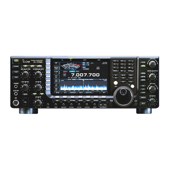
Icom ic-7700 Instruction Manual
Hf/50 mhz
Hide thumbs
Also See for ic-7700:
- Instruction manual (218 pages) ,
- Installation and connections (11 pages) ,
- Service manual (8 pages)
Table of Contents

Subscribe to Our Youtube Channel
Related Manuals for Icom ic-7700


Summary of Contents for Icom ic-7700
-
Page 1: Instruction Manual
HF/50 MHz TRANSCEIVER i7700 Instruction Manual A-6937H-1EX-y Printed in Japan © 2011–2015 Icom Inc. -
Page 2: Explicit Definitions
FOREWORD Thank you for making the IC-7700 your radio of choice. We hope you agree with Icom’s philosophy of “technology first.” Many hours of research and devel- opment went into the design of your IC-7700. D FEATURES ❍ Ultimate receiver performance: third-order intercept (IP3) of +40 dBm (HF bands only) ❍... - Page 3 CAUTION: Changes or modifications to this device, may be reduced, and the transceiver may be dam- aged. not expressly approved by Icom Inc., could void your authority to operate this device under FCC regula- CAUTION: The transceiver weighs approximately tions.
-
Page 4: Supplied Accessories
SUPPLIED ACCESSORIES !5 6 * May differ from that shown depending on the version. q AC power cable* ..........1 † These screws are used when removing the rack mounting w Feet .............. 1 pair handles. See p.2-3 for the rack mounting handle detach- e Spare fuse (FGB 2 A) ......... -
Page 5: Table Of Contents
D Rear panel—2 ................2-7 ■ Linear amplifier connections ............. 2-8 D Connecting the IC-PW1/EURO ............ 2-8 D Connecting a non-Icom linear amplifier ........2-8 ■ Transverter jack information ............. 2-9 ■ FSK and AFSK connections ............. 2-9 D When using the ACC socket or the microphone connector ..2-9 ■... - Page 6 TABLE OF CONTENTS ■ Meter indication selection ............... 3-10 D Multi-function digital meter ............3-10 D Meter type selection ..............3-11 ■ Voice synthesizer operation ............3-11 ■ Basic transmit operation ..............3-12 D Transmitting ................3-12 D Microphone gain adjustment ............3-12 D Drive gain adjustment ..............
- Page 7 TABLE OF CONTENTS D Convenient functions for transmit ..........4-31 ■ Repeater operation ................. 4-32 D Repeater access tone frequency setting ........4-33 ■ Tone squelch operation ..............4-34 ■ Data mode (AFSK) operation ............4-35 Section 5 FUNCTIONS FOR RECEIVE ■ Spectrum scope screen ..............5-2 D Center mode .................
- Page 8 TABLE OF CONTENTS Section 7 VOICE RECORDER FUNCTIONS ■ Recording a QSO audio ……………………………………………… 7-2 D To start or stop recording …………………………………………… 7-2 ■ Recording quick operation …………………………………………… 7-2 D To start or stop recording …………………………………………… 7-2 ■ Playing back recorded audio (QSO) ………………………………… 7-3 D Basic playing …………………………………………………………...
- Page 9 TABLE OF CONTENTS Section 9 SCANS ■ Scan types ..................9-2 ■ Preparation ..................9-2 ■ Voice squelch control function ............9-3 ■ Scan set mode ................. 9-3 ■ Programmed scan operation ............9-4 ■ ∂F scan operation ................9-4 ■...
- Page 10 TABLE OF CONTENTS Section 13 MAINTENANCE ■ Troubleshooting ................13-2 D Transceiver power ............... 13-2 D Transmit and receive ..............13-2 D Scanning ..................13-3 D Display ..................13-3 D Format USB flash drive .............. 13-3 ■ Main dial brake adjustment ............13-3 ■...
- Page 11 PANEL DESCRIPTION Section ■ Front panel ..................1-2 ■ Rear panel ..................1-12 ■ LCD display ..................1-14 ■ Screen menu arrangement ............. 1-16...
-
Page 12: Panel Description
PANEL DESCRIPTION ■ Front panel i o !0 !1 !2 !3 !4 SPLIT LOCK POWER TRANSMIT BK-IN MONITOR RF PWR KEY SPEED DELAY GENE F-INP TUNER MP-W MP-R TIMER PHONES ELEC-KEY AGC VR AUTO RTTY/PSK AM/FM DATA M.SCOPE EXIT/SET LOCK TUNE PLAY DRIVE... - Page 13 Monitors your transmitted IF signal. Recommended level for • The CW sidetone functions regardless of MONITOR an Icom microphone switch setting in the CW mode. Increases • The [MONITOR] indicator above this switch lights green while the function is activated.
- Page 14 • USB keyboards* are supported. !8 NOISE BLANKER CONTROL [NB] *: A USB flash drive or USB keyboard is not supplied (outer control; p. 5-17) by Icom. Adjust the noise blanker threshold level. • To use this control, push About the [USB] connector: Deep •...
- Page 15 PANEL DESCRIPTION @6 COMPRESSION LEVEL CONTROL [COMP] @1 NOISE REDUCTION SWITCH (p. 5-18) (p. 6-5) Push to switch DSP noise reduction ON or OFF. Adjusts the speech compression level in SSB. • The [NR] indicator above this switch lights green when the function is activated.
- Page 16 PANEL DESCRIPTION ■ Front panel (continued) #4 #5 $0 $1 TWIN-PBT SPLIT LOCK HF/50MHz TRANSCEIVER i7700 FILTER PBT-CLR BK-IN MONITOR KEY SPEED DELAY GENE F-INP DIGI-SEL NOTCH DIGI-SEL MP-W MP-R APF/TPF NOTCH RIT/∂TX ∂TX CLEAR CW PITCH SPEECH AUTO RTTY/PSK AM/FM DATA M.SCOPE...
- Page 17 (pp. 4-33, 4-34) other stacked frequencies in the band. (p. 3-4) ➥ Selects the tone set mode when held • Icom’s triple band stacking register memorizes 3 fre- down for 1 second in the FM mode. quencies in each band.
- Page 18 PANEL DESCRIPTION ■ Front panel (continued) $9 %0 TWIN-PBT SPLIT LOCK HF/50MHz TRANSCEIVER i7700 FILTER PBT-CLR BK-IN MONITOR KEY SPEED DELAY F-INP GENE DIGI-SEL NOTCH DIGI-SEL MP-W MP-R APF/TPF NOTCH RIT/∂TX ∂TX CLEAR CW PITCH SPEECH AUTO RTTY/PSK AM/FM DATA M.SCOPE EXIT/SET LOCK...
- Page 19 PANEL DESCRIPTION $7 MEMO PAD-WRITE SWITCH (p. 8-7) %4 VOICE MEMORY RECORD SWITCH MP-W Programs the displayed readout frequency and op- ➥ Push to record the previous received signal for erating mode into a memo pad. the preset time period. (p. 7-7) •...
- Page 20 PANEL DESCRIPTION ■ Front panel (continued) TWIN-PBT SPLIT LOCK RANSCEIVER i7700 FILTER PBT-CLR MONITOR DELAY F-INP GENE DIGI-SEL NOTCH DIGI-SEL MP-W MP-R APF/TPF NOTCH RIT/∂TX ∂TX CLEAR CW PITCH SPEECH AUTO RTTY/PSK AM/FM DATA M.SCOPE EXIT/SET LOCK TUNE SPLIT PLAY DRIVE COMP MONI GAIN...
- Page 21 PANEL DESCRIPTION ^5 MANUAL NOTCH FILTER CONTROL [NOTCH] ^8 CW PITCH CONTROL [CW PITCH] (p. 4-5) (outer control; p. 5-19) Shifts the received CW audio pitch and the CW Varies the notch frequency of the manual notch side tone pitch without changing the operating fre- filter to reject an interfering signal while the manual quency.
-
Page 22: Rear Panel
ANTENNA CONNECTOR 3 [ANT 3] (p. 2-5) nect the IC-7700 to a PC. r ANTENNA CONNECTOR 4 [ANT 4] (p. 2-5) Can be used to remotely control the IC-7700 Accept a 50 Ω antenna with a PL-259 plug con- without the optional CT-17, or for RTTY/PSK31 nector. - Page 23 Connects an external unit, such as preamplifier or !8 ALC INPUT JACK [ALC] (p. 2-8) RF filter, using BNC connectors, if desired. Connects to the ALC output jack of a non-Icom lin- When no external unit is connected, [RX ANT– ear amplifier.
-
Page 24: Lcd Display
PANEL DESCRIPTION ■ LCD display q S/RF METER (pp. 3-10, 3-11) w SHIFT FREQUENCY INDICATOR (p. 5-13) Shows the signal strength while receiving. Shows Shows the shift frequency of the IF filter. the relative output power, SWR, ALC or compres- e BAND WIDTH INDICATOR (p. - Page 25 PANEL DESCRIPTION i APF/TPF INDICATOR @2 SELECT MEMORY CHANNEL INDICATOR (p. 9-7) ➥ “ ” appears when the audio peak filter func- Indicates the displayed memory channel is set as tion is in use. This function is available in CW a select memory channel.
-
Page 26: Screen Menu Arrangement
PANEL DESCRIPTION ■ Screen menu arrangement The following screens can be selected from the start Pushing several times returns to the start EXIT/SET up screen. Choose the desired screen using the fol- up screen. See page 12-3 for set mode arrangement. lowing chart. -
Page 27: Installation And Connections
D Rear panel—2 ................2-7 ■ Linear amplifier connections ............. 2-8 D Connecting the IC-PW1/EURO ............ 2-8 D Connecting a non-Icom linear amplifier ........2-8 ■ Transverter jack information ............. 2-9 ■ FSK and AFSK connections ............. 2-9 D When using the ACC socket or the microphone connector ..2-9 ■... -
Page 28: Unpacking
After unpacking, immediately report any damage to the delivering carrier or dealer. Keep the shipping cartons. For a description and a diagram of accessory equip- ment included with the IC-7700, see ‘Supplied acces- sories’ on page iii of this manual. ■ Main dial attachment... -
Page 29: Rack Mounting Handle Detachment
INSTALLATION AND CONNECTIONS ■ Rack mounting handle detachment The rack mounting handles are supplied attached to FH: Flat head the transceiver to stabilize the transceiver in the shock PH: Pan head absorber material in the box. If you want to remove them, use the supplied screws as described below. -
Page 30: Grounding
In this case, an antenna tuner is useful to match the transceiver and antenna. Low SWR allows full power for transmitting. The IC-7700 has an SWR 30 mm ≈ 1.18 in 10 mm ≈ 0.39 in 1–2 mm ≈ 0.04–0.08 in meter to monitor the antenna SWR continuously. -
Page 31: Required Connections
INSTALLATION AND CONNECTIONS ■ Required connections D Front panel CW key HF/50MHz TRANSCEIVER Connects an electronic keyer. POWER i7700 TRANSMIT BK-IN MONITOR RF PWR KEY SPEED DELAY TUNER A straight or bug key can also be used when the TIMER keyer type is changed in keyer set mode. -
Page 32: Advanced Connections
MAX1A METER [RELAY], [ALC] (p. 2-8) External speaker (p. 15-4) RX ANT IN/OUT Used for connecting a Connects an external non-Icom linear amplifier. preamp or lowpass filter. RX ANT IN/OUT must be SP-34 ACC sockets activated in the antenna (option) (pp. -
Page 33: D Rear Panel-2
INSTALLATION AND CONNECTIONS D Rear panel— 2 Ethernet connector (p. 16-6) External Display Connects a PC Connects a PC-style for remote control monitor display (at least through a LAN or 800×600 resolution). the Internet using Video output signal can the RS-BA1, or be turned ON and OFF for updating the in set mode (p. -
Page 34: Linear Amplifier Connections
16 V/0.5 A DC with initial setting, and 250 V/200 mA with “MOSFET” setting (see page 12-8 for details). RF OUTPUT RF INPUT Use an external relay unit if your non-Icom linear SEND amplifier requires control voltage and/or current greater than specified. -
Page 35: Transverter Jack Information
Refer to the instruction manual for the device prior to connecting it. D When using the ACC socket or the microphone connector Example interface circuit for digital modes (Not provided by Icom) 2 k˘:2 k˘ 10 k˘ Shield cable ¡When connecting to [ACC1] 10 k˘... -
Page 36: Microphones (Options)
INSTALLATION AND CONNECTIONS ■ Microphones (options) D SM-50 q PTT SWITCH TOP VIEW Hold down to transmit, release to receive. w PTT LOCK SWITCH Push to lock the PTT switch in the transmit mode. e UP/DOWN SWITCHES [UP]/[DN] Change the selected readout frequency or memory channel. -
Page 37: Microphone Connector Information
“High” level r Squelch switch CAUTION: DO NOT short pin 2 to ground as this can damage the internal 8 V regulator. DC voltage is applied to pin 1 for microphone operation. Use caution when using a non-Icom microphone. 2-11... -
Page 38: Accessory Connector Information
“1SS133,” on the load side of the circuit to the counter-electromotive force absorption. When the diode is added, a switching delay of the relay may occur. Be sure to check its switching action before operation. [Example] Switching diode ACC 1/2 To a non-Icom sockets linear amplifier e SEND Relay u 13.8 V... -
Page 39: Basic Operations
BASIC OPERATIONS Section ■ When first applying power (CPU resetting) ........3-2 ■ Initial settings ..................3-2 ■ Selecting VFO/memory mode ............3-3 ■ VFO selection ................... 3-3 D Selecting VFO-A/VFO-B ............... 3-3 D VFO equalization ................3-3 ■ Selecting an operating band ............. 3-4 D Using the band stacking registers .......... -
Page 40: When First Applying Power (Cpu Resetting)
BASIC OPERATIONS ■ When first applying power (CPU resetting) Before first applying power, make sure all connections required for your system are complete by referring to Section 2. Then, reset the transceiver using the fol- lowing procedure. Resetting CLEARS all programmed contents in memory channels and returns programmed values in set mode to default values. -
Page 41: Selecting Vfo/Memory Mode
BASIC OPERATIONS ■ Selecting VFO/memory mode ➥ Push to switch between VFO and memory modes. • “ ” or “ ” appears when in VFO mode, or the VFO-A VFO-B selected memory channel number appears when in memory mode. • Holding down for 1 second transfers the con- tents of the selected memory channel to VFO. -
Page 42: Selecting An Operating Band
BASIC OPERATIONS ■ Selecting an operating band The triple band stacking register provides 3 memories Band keys for each band key, storing frequency and mode infor- mation. This function is convenient when you operate 3 modes on one band. For example, one register is used for a CW frequency, another for an SSB fre- quency and the other one for an RTTY frequency. -
Page 43: Frequency Setting
BASIC OPERATIONS ■ Frequency setting The transceiver has several tuning methods for con- venient frequency tuning. D Tuning with the main dial q Push the desired band key on the keypad 1–3 Band keys times. • Three different frequencies can be selected on each band with the band key. -
Page 44: D Quick Tuning Step
BASIC OPERATIONS D Quick tuning step The operating frequency can be changed in larger steps (0.1, 1, 5, 9, 10, 12.5, 20 or 25 kHz selectable) for quick tuning. q Push [TS] to turn the quick tuning function ON. • “Z” appears when the quick tuning function is ON. w Rotate the main dial to change the frequency in programmed kHz steps. -
Page 45: D Selecting 1 Hz Step
BASIC OPERATIONS D Selecting 1 Hz step A minimum tuning step of 1 Hz can be used for fine tuning. q Push [TS] to turn the quick tuning function OFF. w Hold down [TS] for 1 second to turn the 1 Hz tun- ing step ON or OFF. -
Page 46: Operating Mode Selection
CW, CW reverse (CW-R), RTTY, RTTY reverse (RTTY-R), PSK, PSK reverse (PSK-R), AM, AM data, FM and FM data modes are selectable in the IC-7700. Select the desired operation mode as follows. To select a mode of operation, push the desired mode switch momentarily. -
Page 47: Volume Setting
BASIC OPERATIONS ■ Volume setting ➥ Rotate [AF] control clockwise to increase, counter- clockwise to decrease the audio output level. [AF] Audio output increases Audio output decreases ■ RF gain adjustment ➥ Rotate [RF] control clockwise to increase, counter- clockwise to decrease the receiver sensitivity. NOTE: When [RF] control is adjusted CCW in FM mode, audio output decreases then disappears. -
Page 48: Meter Indication Selection
ALC level readout readout the final amplifier MOSFETs. readout D Multi-function digital meter The IC-7700 can display the multi-function digital meter on the LCD display. This meter displays all transmit parameters simultaneously. P-HOLD METER q Hold down [METER] for 1 second to turn the multi- function digital meter ON. -
Page 49: D Meter Type Selection
BASIC OPERATIONS D Meter type selection A total of 3 meter types are available in the IC-7700— Standard, Edgewise and Bar meters. Follow the instructions below for the meter type selec- tion. q Push EXIT/SET several times to return to normal screen, if necessary. -
Page 50: Basic Transmit Operation
BASIC OPERATIONS ■ Basic transmit operation Before transmitting, monitor your selected operating frequency to make sure transmitting won’t cause interference to other stations on the same frequency. It’s good amateur practice to listen first, and then, even if nothing is heard, ask “is the frequency in use”... -
Page 51: D Drive Gain Adjustment
BASIC OPERATIONS D Drive gain adjustment The drive gain is active for all modes other than SSB METER mode with speech compressor OFF. The [DRIVE] control adjusts the gain of the driver stage. Before transmitting, monitor your selected operating frequency to make sure transmitting won’t cause in- terference to other stations on the same frequency. -
Page 52: D Programming The User Band Edge
BASIC OPERATIONS D Programming the user band edge q Select the Others set mode and select the “Beep (Band Edge)” option. w Rotate the main dial to select either the “ON (User)” or “ON (User) & TX Limit” setting. • [BAND] appears above e Push [BAND] to open the band edge screen. -
Page 53: Receive And Transmit
RECEIVE AND TRANSMIT Section ■ Operating SSB .................. 4-2 D Convenient functions for receive ...........4-2 D Convenient functions for transmit ..........4-3 D About 5 MHz band operation (USA version only) ......4-3 ■ Operating CW ................... 4-4 D Convenient functions for receive ...........4-4 D Convenient functions for transmit ..........4-5 D About CW reverse mode ...............4-5 D About CW pitch control ..............4-5... -
Page 54: Operating Ssb
RECEIVE AND TRANSMIT ■ Operating SSB [MIC] [TX] indicator [RX] indicator Band keys q Push a band key to select the desired band. w Push to select LSB or USB. • “USB” or “LSB” appears. • Below 10 MHz LSB is automatically selected; above 10 MHz USB is automatically selected. -
Page 55: D Convenient Functions For Transmit
RECEIVE AND TRANSMIT D Convenient functions for transmit • Speech compressor (p. 6-5) • Transmit quality monitor (p. 6-4) ➥ Push [COMP] to turn the speech compres- (MF6) ➥ Push MONITOR to turn the monitor function ON sor ON or OFF. or OFF. -
Page 56: Operating Cw
RECEIVE AND TRANSMIT ■ Operating CW [KEY SPEED] [TX] indicator [RX] indicator Band keys q Push a band key to select the desired band. w Push to select CW. • After CW mode is selected, push to toggle be- tween CW and CW-R modes. •... -
Page 57: D Convenient Functions For Transmit
RECEIVE AND TRANSMIT D Convenient functions for transmit • Break-in function (p. 6-3) ➥ Push BK-IN several times to select the break- in OFF, semi break-in and full break-in. • “ ” or “ ” appears when the semi break- BKIN F-BKIN in or full break-in function is ON, respectively. -
Page 58: D Apf (Audio Peak Filter) Operation
RECEIVE AND TRANSMIT D APF (Audio Peak Filter) operation The APF changes the audio frequency response by boosting a particular frequency to enhance a desired APF/TPF CW signal. The peak frequency can be adjusted with [DIGI-SEL] control when “APF” is selected for “DIGI-SEL VR Op- eration”... -
Page 59: Electronic Keyer Functions
RECEIVE AND TRANSMIT ■ Electronic keyer functions The IC-7700 has a number of convenient functions for the built-in electronic keyer. q During CW mode, push EXIT/SET several times to normal screen, if necessary. w Push [KEYER] to select memor y keyer screen. -
Page 60: D Memory Keyer Screen
RECEIVE AND TRANSMIT D Memory keyer screen Pre-set characters can be sent using the keyer send menu. Contents of the memory keyer are set using the edit menu. • Transmitting –1 – q During CW mode operation, push [KEYER] to select memory keyer screen. w Push to set the transceiver to transmit, TRANSMIT... -
Page 61: D Editing A Memory Keyer
When a PC keyboard is connected to [USB] con- Contents nector on the front panel, the memory keyer con- M1 CQ TEST CQ TEST DE ICOM ICOM TEST tents can also be edited from the keyboard. M2 UR 5NN✱ BK... -
Page 62: D Contest Number Set Mode
RECEIVE AND TRANSMIT D Contest number set mode This menu is used to set the contest (serial) number and count-up trigger, etc. • Setting contents q During CW mode operation, push [KEYER] to select memory keyer screen. w Push to select memory keyer menu, then EXIT/SET push [001] to select contest serial number... -
Page 63: D Keyer Set Mode
RECEIVE AND TRANSMIT D Keyer set mode This set mode is used to set the memory keyer repeat time, dash weight, paddle specifications, keyer type, etc. • Setting contents q During CW mode operation, push [KEYER] to select memory keyer screen. w Push EXIT/SET to select memory keyer menu, then... -
Page 64: Paddle Polarity
RECEIVE AND TRANSMIT D Keyer set mode (continued) Paddle Polarity Normal This item sets the paddle dot-dash polarity. • Normal and reverse polarity can be selected. Keyer Type ELEC-KEY This item selects the keyer type for [ELEC-KEY] • ELEC-KEY, BUG-KEY and Straight key can be se- connector on the front panel. -
Page 65: Operating Rtty (Fsk)
RECEIVE AND TRANSMIT ■ Operating RTTY (FSK) A DSP-based high-quality Baudot RTTY encoder/ decoder is built-in to the IC-7700. When connecting a PC keyboard (p. 2-6), you can operates RTTY without an external RTTY terminal or PC. If you would rather use your RTTY terminal, consult the manual that comes with the RTTY terminal. -
Page 66: D Convenient Functions For Receive
RECEIVE AND TRANSMIT D Convenient functions for receive • Preamp (p. 5-10) • Noise reduction (p. 5-18) ➥ Push [P.AMP] several times to set the (MF3) ➥ Push to turn the noise reduction ON or preamp OFF, preamp 1 ON or preamp 2 ON. OFF. -
Page 67: D Functions For The Rtty Decoder Display
RECEIVE AND TRANSMIT D Functions for the RTTY decoder display q Push a band key to select the desired band. HOLD/CLR WIDE w Push RTTY/PSK to select RTTY. • After RTTY mode is selected, hold down RTTY/PSK 1 second to toggle between RTTY and RTTY-R modes. •... -
Page 68: D Rtty Memory Transmission
RECEIVE AND TRANSMIT D RTTY memory transmission Pre-set characters can be sent using the RTTY memo- ry. Contents of the memory are set using the edit menu. q During RTTY mode operation, push [DECODE] to select RTTY decode screen. w Push [TX MEM] to select RTTY memory screen. -
Page 69: D Editing Rtty Memory
! # $ % & ¥ ? “ ‘ ` ^ + – ✱ / . , : ; = ↵73 GL SK↵ 73 GL SK < > ( ) [ ] { } | _ CQ CQ CQ ↵CQ CQ CQ DE ICOM ICOM ICOM ( For the memory contents set- Symbol K↵... -
Page 70: D Rtty Decode Set Mode
RECEIVE AND TRANSMIT D RTTY decode set mode This set mode is used to set the decode USOS func- tion, time stamp setting, etc. • Setting contents Ω ≈ WIDE q During RTTY mode operation, push [DECODE] to select RTTY decode screen. w Push [<MENU1>] to select the second RTTY decode menu, then push [SET]... - Page 71 RECEIVE AND TRANSMIT D RTTY decode set mode (continued) RTTY TX USOS Explicitly inserts the FIGS character even though it • ON : Inserts FIGS. is not required by the receiving station. • OFF : Does not insert FIGS. RTTY Time Stamp Turn the time stamp (date, transmission or reception •...
-
Page 72: D Data Saving
RECEIVE AND TRANSMIT D Data saving The contents of the RTTY memory and received sig- The USB flash drive is not supplied by Icom. nal can be saved into the USB flash drive. q Dur ing RTTY decode screen display, push... -
Page 73: Operating Psk
RECEIVE AND TRANSMIT ■ Operating PSK A high-quality DSP-based PSK31 encoder/decoder is built-in to the IC-7700. When connecting a PC key- board (p. 2-6), PSK31 operation can be performed without PSK software installed on your PC. If desired, you can also use your PSK software; con- sult the manual that comes with the software. -
Page 74: D Convenient Functions For Receive
RECEIVE AND TRANSMIT D Convenient functions for receive • Preamp (p. 5-10) • Twin PBT (passband tuning) (p. 5-13) ➥ Push [P.AMP] several times to set the ➥ Rotate [TWIN PBT] controls (inner/outer). (MF3) PBT-CLR preamp OFF, preamp 1 ON or preamp 2 ON. •... -
Page 75: D Functions For The Psk Decoder Display
RECEIVE AND TRANSMIT D Functions for the PSK decoder display q Push a band key to select the desired band. AFC/NET WIDE w Push RTTY/PSK to select PSK. • After PSK mode is selected, hold down for 1 RTTY/PSK second to toggle between PSK and PSK-R modes. •... -
Page 76: D Psk Memory Transmission
RECEIVE AND TRANSMIT D PSK memory transmission Previously entered characters can be sent using the PSK memory. Contents of the memory are set using the edit menu. q During PSK mode operation, push [DECODE] to select PSK decode screen. w Push [TX MEM] to select PSK memor y screen. -
Page 77: D Editing Psk Memory
73 GL SK @ ↵ < > ( ) [ ] { } | _ Symbol CQ CQ CQ ↵CQ CQ CQ DE Icom Icom Icom K ( “↵” is for the memory contents set- ↵ ting only.) ↵My transceiver is IC–7700 &... -
Page 78: D Psk Decode Set Mode
RECEIVE AND TRANSMIT D PSK decode set mode This set mode is used to set the FFT scope setting, time stamp setting, etc. • Setting contents q During PSK mode operation, push [DECODE] Ω ≈ WIDE to select PSK decode screen. w Push [<MENU1>] to select PSK decode sec- ond menu, then push [SET]... - Page 79 RECEIVE AND TRANSMIT D PSK decode set mode (continued) PSK Time Stamp (Frequency) Selects the operating frequency display for time • ON : Displays the operating frequency. stamp usage. • OFF : No operating frequency display. NOTE: The frequency won’t be displayed when “OFF”...
-
Page 80: D Data Saving
D Data saving The contents of the PSK memory and received signal The USB flash drive is not supplied by Icom. can be saved into the USB flash drive. q D u r i n g P S K d e c o d e s c r e e n d i s p l ay, p u s h... -
Page 81: Operating Am
RECEIVE AND TRANSMIT ■ Operating AM q Push a band key to select the desired band. [MIC] [TX] indicator [RX] indicator Band keys w Push to select AM. AM/FM • “AM” indicator appears. • After AM mode is selected, push to toggle be- AM/FM tween AM and FM modes. -
Page 82: D Convenient Functions For Transmit
RECEIVE AND TRANSMIT D Convenient functions for transmit • VOX (voice operated transmit) (p. 6-2) • Audio tone control (p. 12-5) ➥ Push to turn the VOX function ON or ➥ Push [SET] then [LEVEL] to enter OFF. level set mode. Select an item with [Y] /[Z] •... -
Page 83: Operating Fm
RECEIVE AND TRANSMIT ■ Operating FM q Push a band key to select the desired band. [MIC] [TX] indicator [RX] indicator Band keys w Push to select FM. AM/FM • “FM” indicator appears. • After FM mode is selected, push to toggle be- AM/FM tween FM and AM modes. -
Page 84: Repeater Operation
RECEIVE AND TRANSMIT ■ Repeater operation A repeater retransmits a received signal on a differ- ent frequency. When using a repeater, the transmit frequency is shifted from the receive frequency by an offset frequency. A repeater can be accessed using split frequency operation with the transmit frequency shifted to the repeater's receive frequency. -
Page 85: D Repeater Access Tone Frequency Setting
RECEIVE AND TRANSMIT D Repeater access tone frequency setting Some repeaters require subaudible tones to be ac- cessed. Subaudible tones are superimposed on your normal signal and must be set in advance. The trans- ceiver has 50 tones from 67.0 Hz to 254.1 Hz. q Select FM mode. -
Page 86: Tone Squelch Operation
RECEIVE AND TRANSMIT ■ Tone squelch operation The tone squelch opens only when receiving a sig- nal containing a matching subaudible tone. You can silently wait for calls from group members using the same tone. q Set the desired frequency band and select FM mode. -
Page 87: Data Mode (Afsk) Operation
RECEIVE AND TRANSMIT ■ Data mode (AFSK) operation When operating RTTY, SSTV, AMTOR or PACKET with your TNC and/or PC software in the AFSK mode, consult the manual that comes with the TNC and/or the software. Band keys q Connect a PC and TNC to the transceiver. (p. 2-9) w Push a band key to select the desired band. -
Page 89: Functions For Receive
FUNCTIONS FOR RECEIVE Section ■ Spectrum scope screen ..............5-2 D Center mode ................. 5-2 D Fixed mode ................... 5-3 D Mini scope screen display ............5-4 D Scope set mode ................5-4 D USB mouse operation ..............5-9 ■ Preamplifier ..................5-10 ■... -
Page 90: Spectrum Scope Screen
The IC-7700 has two modes for the spectrum display— one is center mode, and the other is fixed mode. In addition, the IC-7700 has a mini scope screen to save screen space. D Center mode... -
Page 91: D Fixed Mode
FUNCTIONS FOR RECEIVE D Fixed mode Displays signals within the specified frequency range. Conditions on the selected frequency band can be observed at a glance when using this mode. q Push several times to close any multi- EXIT/SET MARKER HOLD CENT/FIX function screens, if necessary. -
Page 92: D Mini Scope Screen Display
FUNCTIONS FOR RECEIVE D Mini scope screen display The mini scope screen can be displayed with another screen display, such as set mode menu, decode screen, memory list screen, etc. simultaneously. q Set the scope mode (center or fixed), marker, at- tenuator, span, etc. - Page 93 FUNCTIONS FOR RECEIVE D Scope set mode (continued) Scope during Tx (CENTER Type) Turn display of the transmit signal ON or OFF. NOTE: Transmit signal display is available for the center mode only. Max Hold Turn the peak level hold function ON or OFF. CENTER Type Display Filter Center Select the center frequency of the spectrum scope...
- Page 94 FUNCTIONS FOR RECEIVE D Scope set mode (continued) Waterfall Display Set the waterfall display to ON or OFF. • ON : Displays the waterfall of the spectrum scope. • OFF : Does not display the waterfall. Waterfall Peak Color Level Grid 8 The signal level that reaches a peak color is set to Grid 1 to Grid 8 for the waterfall display.
- Page 95 FUNCTIONS FOR RECEIVE D Scope set mode (continued) Fixed Edges ( 0.03 – 1.60) 0.750 – 1.250 Set the scope edge frequencies for fixed mode for • Set the frequencies within 0.030 to 1.600 MHz bands below 1.6 MHz. range in 1 kHz steps. As edge frequencies are set, the other edge fre- quency will be automatically set for a display band width of 5 kHz to a maximum of 500 kHz.
- Page 96 FUNCTIONS FOR RECEIVE D Scope set mode (continued) (20.00 – 22.00) 21.000 – 21.450 Set the scope edge frequencies for fixed mode • Set the frequencies within 20.000 to 22.000 MHz scope when the 20 to 22 MHz band is selected. range in 1 kHz steps.
-
Page 97: D Usb Mouse Operation
FUNCTIONS FOR RECEIVE D USB mouse operation If you connect a USB mouse to the transceiver, a mouse pointer appears on the spectrum scope screen. Now, you can change the frequency by using the mouse. While holding down [XFC], the mouse changes the transmit frequency. -
Page 98: Preamplifier
FUNCTIONS FOR RECEIVE ■ Preamplifier The preamp amplifies received signals in the receiver front end, to improve the S/N ratio and sensitivity. Set this to preamp 1 or preamp 2 when receiving weak signals. ➥ Push [P.AMP] several times to set the (MF3) P.AMP preamp OFF, preamp 1 ON or preamp 2 ON. -
Page 99: Rit Function
FUNCTIONS FOR RECEIVE ■ RIT function The RIT (Receive Increment Tuning) function com- pensates for off-frequency operation of the received station. The function shifts the receive frequency up to ±9.99 kHz in 10 Hz steps without moving the transmit frequency. [RIT/∂TX] q Push to turn the RIT function ON and OFF. -
Page 100: Agc Function
FUNCTIONS FOR RECEIVE ■ AGC function The AGC (auto gain control) controls receiver gain to produce a constant audio output level even when the received signal strength varies greatly. The transceiver has 3 preset AGC characteristics (time constant: fast, mid, slow) for non-FM modes. The FM mode AGC time constant is fixed as ‘FAST’... -
Page 101: Twin Pbt Operation
IF passband width by shifting the IF frequency slightly outside of the IF filter pass- band. The IC-7700 uses DSP for the PBT function. Moving both [TWIN-PBT] controls shifts the IF pass- band center frequency both above and below the re- ceived frequency. -
Page 102: If Filter Selection
FUNCTIONS FOR RECEIVE ■ IF filter selection The transceiver has 3 passband width IF filters for FILTER each mode. For SSB, CW and PSK modes, the passband width can be set within 50 to 3600 Hz in 50 or 100 Hz steps. A total of 41 passband widths are available. -
Page 103: D Roofing Filter Selection
FUNCTIONS FOR RECEIVE D Roofing filter selection The IC-7700 has 3, 6 and 15 kHz roofing filters at the 1st IF frequency. The roofing filter provides interfer- ence reduction from nearby strong signals. q Hold down for 1 second to enter filter set FILTER screen. - Page 104 FUNCTIONS FOR RECEIVE D Filter shape set mode (continued) (600Hz – ) SHARP Select the filter shape for SSB mode in HF bands. The set filter shape is automatically used only when the IF filter is set to 600 Hz or wider. SSB–D (600Hz –...
-
Page 105: Noise Blanker
FUNCTIONS FOR RECEIVE ■ Noise blanker The noise blanker eliminates pulse-type noise such as the noise from car ignitions. The noise blanker is not available for FM mode. q Push to turn the noise blanker function ON or OFF. • [NB] indicator above this switch lights green. w Rotate [NB] control to adjust the noise blanker threshold level. -
Page 106: Noise Reduction
FUNCTIONS FOR RECEIVE ■ Noise reduction The noise reduction function reduces random noise components and enhances desired signals which are buried in noise. The DSP performs the random noise reduction function. q Push to turn the noise reduction ON. • [NR] indicator above this switch lights green. w Rotate the [NR] control to adjust the noise reduc- tion level. -
Page 107: Notch Function
FUNCTIONS FOR RECEIVE ■ Notch function This transceiver has auto and manual notch functions. [NOTCH] control The auto notch function uses DSP to automatically attenuate beat tones, tuning signals, etc., even if they are moving. The manual notch can be set to attenuate a frequency via the [NOTCH] control.The auto notch can be used in SSB, AM and FM mode. -
Page 108: Audio Scope Screen
FUNCTIONS FOR RECEIVE ■ Audio scope screen This audio scope allows you to display the received signal’s frequency component to the FFT scope, and its waveform component to the Oscilloscope. The FFT scope has an waterfall. q Push several times to close any multi- EXIT/SET LEVEL TIME... -
Page 109: D Audio Scope Set Mode
FUNCTIONS FOR RECEIVE D Audio scope set mode This set mode is used to set the FFT scope waveform type, color, waterfall display and oscilloscope wave- form color. q During audio scope display ON, push [SET] to select the Audio scope set mode screen. w Push [Y] or [Z] to select the desired... -
Page 110: Autotune Function
■ Autotune function The Automatic tuning function tunes the displayed frequency (maximum CW: ±500 Hz, AM: ±5 kHz) au- tomatically when an off-frequency signal is received. This function is active while in CW or AM mode is se- lected. ➥ Push [AUTOTUNE] to toggle the autotune function ON or OFF. -
Page 111: Functions For Transmit
FUNCTIONS FOR TRANSMIT Section ■ VOX function ..................6-2 D Using the VOX function ..............6-2 D Adjusting the VOX function ............6-2 D VOX set mode ................6-2 ■ Break-in function ................6-3 D Semi break-in operation ............... 6-3 D Full break-in operation .............. -
Page 112: Vox Function
FUNCTIONS FOR TRANSMIT ■ VOX function The VOX (Voice-Operated Transmission) function switches between transmit and receive with your voice. This function provides “hands-free” operation. D Using the VOX function q Select a phone mode (SSB, AM, FM). w Push to turn the VOX function ON or OFF. •... -
Page 113: Break-In Function
■ Break-in function The break-in function is used in CW mode to auto- matically toggle the transceiver between transmit and receive when keying. The IC-7700 is capable of full break-in or semi break-in. D Semi break-in operation During semi break-in operation, the transceiver im- mediately transmits when keyed and during key up periods returns to receive after a pre-set delay. -
Page 114: Tx Function
FUNCTIONS FOR TRANSMIT ■ ∂TX function The ∂TX function shifts the transmit frequency up to ±9.999 kHz in 1 Hz steps (10 Hz steps when cancel- ling the 1 Hz step readout) without moving the receive frequency. [RIT/∂TX] q Push ∂TX •... -
Page 115: Transmit Filter Width Setting (Ssb Only)
FUNCTIONS FOR TRANSMIT ■ Transmit filter width setting (SSB only) The transmit filter width for SSB mode can be se- lected from wide, middle and narrow. ➥ During USB or LSB mode selection, hold down COMP [COMP] for 1 second several times to select (MF6) the desired transmit filter width from wide, middle and narrow. -
Page 116: Split Frequency Operation
FUNCTIONS FOR TRANSMIT ■ Split frequency operation Split frequency operation allows you to transmit and receive in the same mode on two different frequen- cies. Split frequency operation is performed using 2 frequencies on the main and sub readouts. The following is an example of setting 21.290 MHz for receiving and 21.310 MHz for transmitting. -
Page 117: Quick Split Function
FUNCTIONS FOR TRANSMIT ■ Quick split function When you find a DX station, an important considera- tion is how to set the split frequency. When you hold down the switch for 1 second, SPLIT split frequency operation is turned ON and the trans- mit frequency is equalized to the received frequency. -
Page 119: Recording A Qso Audio ...................................................... 7-2 D To Start Or Stop Recording
VOICE RECORDER FUNCTIONS Section ■ Recording a QSO audio ……………………………………………… 7-2 D To start or stop recording …………………………………………… 7-2 ■ Recording quick operation …………………………………………… 7-2 D To start or stop recording …………………………………………… 7-2 ■ Playing back the recorded audio (QSO) …………………………… 7-3 D Basic playing …………………………………………………………... -
Page 120: Voice Recorder Functions
VOICE RECORDER FUNCTIONS ■ Recording a QSO audio The Voice recorder function records a QSO (communi- NOTE: cation) audio onto a USB flash drive. • Be sure to connect a USB flash drive before re- This function enables you to record both received and cording a QSO audio. -
Page 121: Playing Back Recorded Audio (Qso)
VOICE RECORDER FUNCTIONS ■ Playing back the recorded audio (QSO) D Basic playing q Push several times to close a multi-func- EXIT/SET tion screen, if necessary. w Push [VOICE] to display the Voice Recorder menu. e Push [QSO PLAY] to call up the voice QSO player screen. -
Page 122: D Operating While Playing Back
VOICE RECORDER FUNCTIONS ■ Playing back the recorded audio (QSO) (continued) D Operating while playing back You can fast forward or rewind while playing back. • Fast forward while playing Push [ to fast forward to the skip time point. ... -
Page 123: Deleting Recorded Audio File
VOICE RECORDER FUNCTIONS ■ Deleting recorded audio file q Push several times to close a multi-func- EXIT/SET tion screen, if necessary. w Push [VOICE] to display the Voice Recorder menu. e Push [QSO PLAY] to call up the voice QSO player screen. -
Page 124: About Digital Voice Recorder
VOICE RECORDER FUNCTIONS ■ About digital Voice Recorder The IC-7700 has digital voice memories, up to 4 mes- sages for transmit, and up to 20 messages for re- ceive. A maximum message length of 30 seconds can be re- corded into a receive memory (total message length... -
Page 125: Recording A Received Audio (Short Rec)
■ Recording a received audio (Short REC) Up to 20 channels of receive voice memories are available in the IC-7700. And the total audio length of up to 209 seconds can be recorded in receive channels. However, the maximum recordable length into a single memory is 30 seconds. -
Page 126: Protect The Recorded Contents
VOICE RECORDER FUNCTIONS ■ Playing the recorded audio (continued) D One-touch playing The previously recorded audio in message 1 can be played back without selecting voice recorder screen. ➥ Push momentarily to play back the last 5 PLAY seconds of the previously recorded audio. •... -
Page 127: Recording A Message For Transmit
To transmit a message using the Voice recorder, record the desired message in advance as described below. The IC-7700 has digital voice memories for transmis- sion, up to 4 messages and you can record message in length of up to 99 seconds. -
Page 128: Programming A Memory Name
VOICE RECORDER FUNCTIONS ■ Programming a memory name Memory messages can be tagged with alphanumeric names of up to 20 characters each. Capital letters, small letters, numerals, some symbols (! # $ % & ¥ ? “ ‘ ` ^ + – ✱ / . , : ; = < > ( ) [ ] { } | _ and spaces can be used. -
Page 129: Sending A Recorded Message
VOICE RECORDER FUNCTIONS ■ Sending a recorded message D Single TX q Push EXIT/SET several times to close a multi-func- tion screen, if necessary. w Select a phone mode by pushing AM/FM e Push [VOICE] to enter the Voice recorder menu. -
Page 130: D Transmit Level Setting
VOICE RECORDER FUNCTIONS ■ Sending a recorded message (continued) D Transmit level setting q Call up the Voice recorder screen as described above. w Push [TX LEV.] to select the voice memory transmit level set condition. e Push the desired message switch, [T1] [T4] , momentarily to transmit the contents. -
Page 131: Voice Set Mode
VOICE RECORDER FUNCTIONS ■ Voice set mode Sets the automatic monitor function, short play and normal recording times for voice recorder. q Push EXIT/SET several times to close a multi-func- tion screen, if necessary. w Push [VOICE] to display the Voice recorder menu. -
Page 132: Rx Rec Condition
VOICE RECORDER FUNCTIONS ■ Voice set mode (continued) QSO REC Mode TX&RX Select the recording mode for recording a QSO • TX&RX : Records both the transmitted and received audio. audio. • RX only : Records only the received audio. RX REC Condition Squelch Auto Select whether or not the squelch status affects the... -
Page 133: D Saving The Received Audio Memory
■ Saving a voice message into the USB flash drive D Saving the received audio memory The recorded RX memory contents can be saved into The USB flash drive is not supplied by Icom. the USB flash drive. q During Voice recorder RX memory screen display,... -
Page 135: Memory Operation
MEMORY OPERATION Section ■ Memory channels ................8-2 ■ Memory channel selection ..............8-2 D Using the keys ............8-2 ∫ √ D Using the keypad ................8-2 ■ Memory channel programming ............8-3 D Programming in VFO mode ............8-3 D Programming in memory mode ............ -
Page 136: Memory Channels
MEMORY OPERATION ■ Memory channels The transceiver has 101 memory channels. Memory mode is very useful for quickly changing to often-used frequencies. All 101 memory channels are tuneable which means the programmed frequency can be tuned temporarily with the main dial, etc. in memory mode. MEMORY MEMORY TRANSFER... -
Page 137: Memory Channel Programming
MEMORY OPERATION ■ Memory channel programming Memory channel programming can be preformed ei- ther in VFO mode or in memory mode. D Programming in VFO mode q Set the desired frequency, operating mode and fil- ter width in VFO mode. ∫... -
Page 138: Frequency Transfers
MEMORY OPERATION ■ Frequency transfers The frequency and operating mode in a memory channel can be transferred to the VFO. Frequency transfers can be performed in either VFO mode or memory mode. D Transferring in VFO mode This is useful for transferring programmed contents to TRANSFER EXAMPLE IN VFO MODE Operating frequency : 21.320 MHz/USB (VFO) a VFO. -
Page 139: Memory List Screen
MEMORY OPERATION ■ Memory list screen The memory list screen simultaneously shows 9 memory channels and their programmed contents. 15 memory channels can be displayed in the wide memory list screen. You can select a desired memory channel from the memory list screen. -
Page 140: Memory Names
MEMORY OPERATION ■ Memory names All memory channels (including scan edges) can be tagged with alphanumeric names of up to 10 charac- ters each. Capital letters, small letters, numerals, some symbols (! # $ % & ¥ ? " ’ ` ^ + – ✱ / . , : ; = < > ( ) [ ] { } | _ and spaces can be used. -
Page 141: Memo Pads
MEMORY OPERATION ■ Memo pads The transceiver has a memo pad function to store fre- quency and operating mode for easy write and recall. The memo pads are separate from memory channels. The default number of memo pads is 5, however, this can be increased to 10 in set mode if desired. - Page 143 SCANS Section ■ Scan types ..................9-2 ■ Preparation ..................9-2 ■ Voice squelch control function ............9-3 ■ Scan set mode ................. 9-3 ■ Programmed scan operation ............9-4 ■ ∂F scan operation ................9-4 ■ Fine programmed scan/Fine ∂F scan ..........9-5 ■...
-
Page 144: Scans
SCANS ■ Scan types • The scan function can be used on the main read- out only. • You can perform a scan while operating on a fre- quency using the split functions. PROGRAMMED SCAN ∂F SCAN Repeatedly scans between two scan edge frequencies Repeatedly scans within ∂F span area. -
Page 145: Voice Squelch Control Function
SCANS ■ Voice squelch control function This function is useful when you don’t want unmodu- lated signals pausing or cancelling a scan. When the voice squelch control function is activated, the trans- ceiver checks received signals for voice components. If a received signal includes voice components, and the tone of the voice components changes within 1 second, scan pauses (or stops). -
Page 146: Programmed Scan Operation
SCANS ■ Programmed scan operation q Push several times to close a multi-func- EXIT/SET tion screen, if necessary. w Select VFO mode. e Select the desired operating mode. • The operating mode can also be changed while scan- ning. r Push [SCAN] to select the scan screen. -
Page 147: Fine Programmed Scan/Fine ∂F Scan
SCANS ■ Fine programmed scan/Fine ∂F scan In fine scan (programmed or ∂F), the scan speed de- creases when the squelch opens, but the transceiver keeps scanning. The scanning tuning step shifts from 50 Hz to 10 Hz when the squelch opens. q Push several times to close a multi-func- EXIT/SET... -
Page 148: Memory Scan Operation
SCANS ■ Memory scan operation q Push several times to close a multi-func- EXIT/SET tion screen, if necessary. w Select memory mode. e Push [SCAN] to select the scan screen. r Set [SQL] open or closed. • See page 9-2 for squelch condition. t Push [MEMO] to start the memory scan. -
Page 149: Setting Select Memory Channels
SCANS ■ Setting select memory channels D Setting in scan screen q Push several times to close a multi-func- EXIT/SET tion screen, if necessary. w Select memory mode. e Push [SCAN] to select the scan screen. r Select the desired memory channel to set as a se- lect memory channel. -
Page 150: Tone Scan
SCANS ■ Tone scan The transceiver can detect subaudible tones in a received signal. By monitoring a signal that is being transmitted on a repeater input frequency, you can determine the tone frequency required to access the repeater. q Set the desired frequency or memory channel to T-SCAN be checked for a tone frequency. -
Page 151: Antenna Tuner Operation
ANTENNA TUNER OPERATION Section ■ Antenna connection and selection ..........10-2 ■ Antenna memory settings ............... 10-3 D Antenna type selection ............... 10-3 D Temporary memory ..............10-4 D Antenna selection mode ............. 10-4 D Receive antenna I/O setting ............10-5 ■... -
Page 152: Antenna Connection And Selection
ANTENNA TUNER OPERATION ■ Antenna connection and selection The IC-7700 has 4 antenna connectors for the HF/50 MHz bands, [ANT1], [ANT2], [ANT3], and [ANT4]. For each operating band the IC-7700 covers, there is a band memory which memorizes the selected antenna. -
Page 153: Antenna Memory Settings
ANTENNA TUNER OPERATION ■ Antenna memory settings This function stores the antenna connector number for each frequency band. q Push several times to close multi-function EXIT/SET Band keys screen, if necessary. w Hold down [ANT] for 1 second to select an- (MF1) tenna set screen. -
Page 154: D Temporary Memory
ANTENNA TUNER OPERATION ■ Antenna memory settings (continued) D Temporary memory The antenna temporary memory memorizes the man- ually selected antenna. The selected antenna will be re-called even if frequency band has been changed. q Select the antenna set screen. w Push [TEMP-M] to turn the temporary mem- ory ON or OFF. -
Page 155: D Receive Antenna I/O Setting
ANTENNA TUNER OPERATION D Receive antenna I/O setting In the default setting, receive antenna connectors, [RX ANT-IN] and [RX ANT-OUT], on the rear panel are deactivated and are connected internally by the switching relay. If you want to connect an external preamp or low-pass filter between the [RX ANT-IN] and [RX ANT-OUT], you must activate them as de- scribed below. -
Page 156: Antenna Tuner Operation
ANTENNA TUNER OPERATION ■ Antenna tuner operation The internal automatic antenna tuner matches the transceiver to the connected antenna automatically. After the tuner matches an antenna, the variable ca- pacitor settings are memorized as a preset point for each frequency range (100 kHz steps). Therefore, when you change the frequency range, the variable capacitors are automatically preset to the memorized setting. -
Page 157: D If The Tuner Cannot Tune The Antenna
When using an external antenna tuner such as the IC-PW1’s tuner, tune with the external antenna tuner, and turn OFF the IC-7700’s tuner. After tuning is com- pleted, turn the internal tuner ON. Otherwise, both tuners tune simultaneously and correct tuning may not be obtained. - Page 159 CLOCK AND TIMERS Section ■ Time set mode ................11-2 ■ Daily timer setting ................11-3 ■ Setting sleep timer ................11-4 ■ Timer operation ................11-4 11-1...
-
Page 160: Time Set Mode
CLOCK AND TIMERS ■ Time set mode The IC-7700 has a built-in calendar and 24-hour clock EDIT (accuracy ±75 seconds per month) with daily power Symbol ON/OFF timer functions. Before operating these timer functions, set the current date and time. -
Page 161: Daily Timer Setting
CLOCK AND TIMERS ■ Daily timer setting The transceiver turns power ON and/or OFF automat- ically on the specified day and time, with the specified frequency settings. q Push several times to close multi-function EXIT/SET TIMER2 ≈ TIMER4 TIMER5 screen, if necessary. w Hold down for 1 second to select timer set TIMER... -
Page 162: Setting Sleep Timer
CLOCK AND TIMERS ■ Setting sleep timer The sleep timer turns the transceiver power OFF au- tomatically after passing the set period. The timer can be set to 5–120 minutes in 5 minute steps. The sleep timer function counts the ‘minute’ units, and does not count the ‘second’... -
Page 163: Set Mode
SET MODE Section ■ Set mode description ..............12-2 D Set mode operation ..............12-2 D Screen arrangement ..............12-3 ■ Level set mode ................12-4 ■ ACC set mode ................12-7 ■ Display set mode ................12-10 ■ Others set mode ................12-12 ■... -
Page 164: Set Mode Description
■ Set mode description Set mode is used for programming infrequently changed values or conditions of functions. The IC-7700 has a level set mode, display set mode, time set mode, accessory set mode, others set mode and USB-Memory set menu. -
Page 165: D Screen Arrangement
SET MODE D Screen arrangement • Display set mode (p. 12-10) • Set mode menu screen (p. 12-2) • Time set mode (p. 11-2) • Level set mode (p. 12-4) • Others set mode (p. 12-12) • ACC set mode (p. 12-7) •... -
Page 166: Level Set Mode
SET MODE ■ Level set mode RX HPF/LPF – – – – – – – Sets the high-pass filter (100 Hz to 2000 Hz) and low-pass filter (500 Hz to 2400) of the receive audio NOTE: When this setting is active, below 2 items in 100 Hz steps in SSB mode. - Page 167 SET MODE ■ Level set mode (continued) RX HPF/LPF – – – – – – – Sets the high-pass filter (100 Hz to 2000 Hz) and low-pass filter (500 Hz to 2400) of the receive audio in 100 Hz steps in CW mode. (default: OFF) RTTY RX HPF/LPF –...
-
Page 168: Speech Level
SET MODE ■ Level set mode (continued) SSB TBW (WIDE) 100 – 2900 Sets the transmission passband width to a wide Lower freq. : 100 (default), 200, 300 and 500 Hz setting by changing the lower and higher cut-off fre- Higher freq. -
Page 169: Acc Set Mode
SET MODE ■ ACC set mode 50 % ACC AF Output Level Sets the desired audio output level, output from • Outputs approximately 200 mV at 50% (default) setting. [ACC1], within 0 to 100% in 1% steps. 100 % S/PDIF Output Level Sets the desired output level of [S/P DIF], within 0 to 100% in 1% steps. - Page 170 : Use mechanical relay. Reed and MOSFET. (16 V DC/0.5 A maximum) Select the suitable relay type when connecting a • MOS-FET: Use semiconductor type relay. non-Icom linear amplifier. (250 V/200 mA maximum: default) External Meter Output Auto Selects the desired item for an external meter indi- •...
-
Page 171: Ref Adjust
7700. Turn the transceiver power OFF then ON to make the setting effective. • OFF : Not input/output the reference signal. (default) • OUT : Outputs the IC-7700 reference signal to externally connected equipment(s) for their reference. NOTE: If the applied reference signal is off-fre- quency, or no signal is applied with “IN”... -
Page 172: Display Set Mode
SET MODE ■ Display set mode 50 % LCD Unit Bright Adjusts the LCD unit brightness from 0 (dark) to 100% (bright) range in 1% steps. (default: 50%) Backlight (Switches) Adjusts the switch indicators brightness from 1 (dark) to 100 (bright) range in 1 steps. (default: 80) Display Type Selects the desired display type from A (Black back) See page13-4 for details. -
Page 173: External Display
SET MODE ■ Display set mode (continued) MN–Q Popup (MN OFF ON) Enables the pop-up display capability for the notch filter width when the manual notch filter is turned ON. (default: ON) Screen Saver Function 60min Turns the screen saver function ON (15, 30 or 60 The screen saver will activate when no operation is minutes) and OFF. -
Page 174: Others Set Mode
If the device’s transmit/re- (10, 15, 20, 25 or 30 milliseconds). ceive switching time is slower than the time for the Icom transceiver, the device may not yet ready for a transmitted signal, and could be damaged by the transceivers RF power. -
Page 175: Others Set Mode
SET MODE ■ Other set mode (continued) TX Delay (50M) Sets the transmission’s timing for the 50 MHz band. See the previous item “TX Delay (HF)” for more de- tails. Time–Out Timer (CI–V) Turns the Time-Out Timer function ON (3, 5, 10, 20 or 30 minutes) or OFF. - Page 176 SET MODE ■ Other set mode (continued) Tuner (Auto Start) The internal antenna tuner has an automatic start • OFF : The tuner remains OFF even when the SWR capability which starts tuning if the SWR is higher is poor (1.5–3:1). (default) than 1.5–3:1.
-
Page 177: Memopad Numbers
SET MODE ■ Other set mode (continued) SPEECH S-Level The IC-7700 speech processor can announce When “OFF” is selected, the signal level is not an- frequency, mode and signal level. Signal level an- nounced. nouncement can be deactivated if desired. -
Page 178: Cw Normal Side
SET MODE ■ Other set mode (continued) SSB/CW Synchronous Tuning Selects the displayed frequency shift function from • ON : The displayed frequency shifts when the op- ON and OFF. (default: OFF) erating mode is changed between SSB and When this function is activated, the audio pitch or •... - Page 179 SET MODE ■ Other set mode (continued) External Keypad (PSK) Sets the external keypad for PSK memory transmis- • ON : In the PSK mode, and while the PSK decode sion capability ON or OFF. screen is active, pushing one of the external keypad switches transmits the desired PSK Only PSK memory channels PT1, PT2, PT3 and PT4 memory contents.
- Page 180 ■ Other set mode (continued) CI–V Address To distinguish equipment, each CI-V transceiver has When 2 or more IC-7700’s are connected to an op- its own Icom standard address in hexadecimal code. tional CT-17 , rotate the main v level converter The IC-7700’s address is 74h.
- Page 181 (Valid after Reboot) 192. 168. 0. 10 Sets IP address for the IC-7700 when connecting to Turn the transceiver power OFF then ON to make your PC or LAN (Local Area Network) through the the setting effective. See page 16-7 for details.
- Page 182 Serial Port (UDP) (Valid after Reboot) 50002 Sets the Serial port of the IC-7700 by accessing from Turn the transceiver power OFF then ON to make the remote station. the setting effective. Only when you configure the remote control system using an optional RS-BA1, you need this setting.
- Page 183 Network User2 ID Register the Users ID to allow them to remotely ac- See the Network User1 ID on the previous page for cess the IC-7700. The IC-7700 can register three setting details. users to Network User1 ID to Network User3 ID.
- Page 184 SET MODE ■ Other set mode (continued) Network AF Sample Rates 8kHz, 12kHz, 16kHz Selects the limitation of the received audio sampling Higher sampling rates will improve the audio qual- rate that Remote stations can adjust. ity. However, they also increase the amount of data, which can cause voice delay or jumpiness, depend- 8 kHz, 12 kHz, 16 kHz, 24 kHz and 48 kHz are se- ing on the network condition.
-
Page 185: Usb-Memory Set Menu
• Setting load screen (p. 12-26) • Firmware update (p. 16-4) Updating the firmware is very risky. If you make a mistake, the IC-7700 may not operate properly, and repair at Icom Inc. (Japan) may be the only way to fix it. -
Page 186: D Save Option Set Mode
“Old Ver,” and indicated in brackets. For your information: NOTE: You cannot write setting file that is saved The current IC-7700 firmware version number can in the current version format to an older firmware be confirmed when turning the power ON and is dis- version IC-7700. -
Page 187: D Load Option Set Mode
SET MODE D Load option set mode Load Contents Select Selects file load condition from All and Select. • All : Loads and sets the all following contents. (default: Select) • Select : Loads and sets the selected contents only. ANT Memory Selects the antenna memory setting loading condi- •... -
Page 188: File Saving
SET MODE ■ File saving Memory channel contents, set mode settings, etc. can be saved into the USB flash drive for backup. q Dur ing set mode menu screen display, push OPTION SAVE WIDE CANCEL [USB] to select USB-Memory set menu screen. w Push [SAVE] to select setting save screen. -
Page 189: File Loading
SET MODE ■ File loading By loading the saved setting file from the USB flash drive, you can easily set up another IC-7700—several operators settings can easily be applied to one IC- 7700. q During set mode menu screen display, push... -
Page 190: Changing A File Name
SET MODE ■ Changing a file name The file name, saved in the USB flash drive, can be re-named from the transceiver as desired. q D u r i n g s e t t i n g s ave s c r e e n d i s p l ay, p u s h WIDE CANCEL [DIR/FILE]... -
Page 191: Deleting A File
SET MODE ■ Deleting a file RECOMMENDATION! Deleting the setting file is irreversible. Confirm the contents before deleting a setting file! q D u r i n g s e t t i n g s ave s c r e e n d i s p l ay, p u s h [DIR/FILE] to select tree view screen. -
Page 192: Formatting Usb Flash Drive
SET MODE ■ Formatting USB flash drive Saved data in the USB flash drive can be erased. IMPORTANT! Formatting erases all saved data in the USB flash drive. Making a backup file on your PC is recommended. q During USB-Memory set menu display, hold down [FORMAT] for 1 second. -
Page 193: Maintenance
MAINTENANCE Section ■ Troubleshooting ................13-2 D Transceiver power ............... 13-2 D Transmit and receive ..............13-2 D Scanning ..................13-3 D Display ..................13-3 D Format USB flash drive .............. 13-3 ■ Main dial brake adjustment ............13-3 ■ SWR reading .................. 13-4 ■... -
Page 194: Troubleshooting
If you are unable to locate the cause of a problem or solve it through the use of this chart, contact your nearest Icom Dealer or Service Center. D Transceiver power PROBLEM POSSIBLE CAUSE SOLUTION REF. -
Page 195: D Scanning
MAINTENANCE D Scanning PROBLEM POSSIBLE CAUSE SOLUTION REF. Programmed scan does • Squelch is open. • Set [SQL] to the threshold point. p. 3-9 not stop. Programmed scan does • The same frequencies have been programmed • Program different frequencies in scan edge p. -
Page 196: Swr Reading
∞ COMP 44 52V ■ Screen type and font selections 2 types of screen images and 5 types of frequency readout display fonts are available in the IC-7700. • Screen image example— q Push EXIT/SET several times to close multi-func-... -
Page 197: Frequency Calibration (Approximate)
WWV, WWVH, or other standard frequency signals. CAUTION: The IC-7700 has been thoroughly adjusted and tested at the factory before being shipped. You should not have to re-calibrate it. q Push to select USB mode. -
Page 198: Opening The Transceiver's Case
Remove 7 screws from the bottom, then lift up the bottom cover. ■ Clock backup battery replacement The IC-7700 has a Lithium backup battery (CR2032) inside for clock and timer functions. The usual life of the backup battery is approximately 2 years. -
Page 199: Fuse Replacement
MAINTENANCE ■ Fuse replacement When no external DC output is available from [EXT DC] and ACC connectors, the internal fuse may be open. Replace the fuse in this case. RWARNING! DISCONNECT the AC power cable from the AC outlet before removing the transceiver’s cover. -
Page 200: About Protection Indications
MAINTENANCE ■ About protection indications The IC-7700 has a 2-step protection function to pro- tect the final power amplifiers. The protector monitors the power amplifier tempera- ture and activates when the temperature becomes extremely high. • Power down transmission Reduces the transmit output power to 100 W. -
Page 201: Control Command
CONTROL COMMAND Section ■ Remote jack (CI-V) information ............14-2 D CI-V connection example ............14-2 D Data format ................. 14-2 D Command table ................14-3 D Data contents description ............14-9 14-1... -
Page 202: Remote Jack (Ci-V) Information
9–15 V DC RS-232C port. The Icom Communications Interface-V (CI-V) controls the transceiver. Up to 4 Icom CI-V transceivers or receivers can be connected to a PC equipped with an RS-232C port. See pages 12-17 and 12-18 for setting the CI-V con- ct- 17 dition using set mode. -
Page 203: D Command Table
CONTROL COMMAND D Command table Cmd. Sub Cmd. Data Description Cmd. Sub Cmd. Data Description see p. 14-10 Send frequency data for transceive Send/read 10 Hz (1 Hz) tuning step see p. 14-10 Send mode data for transceive Send/read 100 Hz tuning step see p. - Page 204 CONTROL COMMAND D Command table (continued) Cmd. Sub Cmd. Data Description Cmd. Sub Cmd. Data Description 0000 to Send/read [AGC] level Speech compressor OFF 0255 (0000=max. CCW to 0255=max. CW) Speech compressor ON 0000 to Send/read NB level Monitor function OFF 0255 (0000=0%, 0255=100%) Monitor function ON...
- Page 205 CONTROL COMMAND D Command table (continued) Cmd. Sub Cmd. Data Description Cmd. Sub Cmd. Data Description 05 0001 see p. 12-4 Send/read SSB RX HPF/LPF 05 0028 0000 to Send/read AF output level to ACC ( HPF: 0=Through, 1=100 to 20=2000, 0255 (0000=0% to 0255=100%) LPF: 5=500 to 24=2400, 25=Through)
- Page 206 CONTROL COMMAND D Command table (continued) Cmd. Sub Cmd. Data Description Cmd. Sub Cmd. Data Description 05 0053 00 to 02 Set/read screen saver type 05 0084 00 to 02 Send/read main dial auto TS (00=Bound, 01=Rotation, 02=Twist) (00=OFF, 01=Low, 02=High) 0054 00/01 Send/read output signal setting for...
- Page 207 CONTROL COMMAND D Command table (continued) Cmd. Sub Cmd. Data Description Cmd. Sub Cmd. Data Description 05 0113 00 to 02 Send/read scope sweep speed for ±100 05 0142 00/01 Send/read RTTY decode new line code kHz span (00=Slow, 01=Mid., 02=Fast) (00=CR,LF,CR+LF, 01=CR+LF) 0114 00 to 02...
- Page 208 CONTROL COMMAND D Command table (continued) Cmd. Sub Cmd. Data Description Cmd. Sub Cmd. Data Description 05 0177 00/01 Send/read antenna temporary memory 05 0202 00, 01 Send/read the internet access line set (00=OFF, 01=ON) setting. 0178 00 to 02 Send/read antenna selection ( 00=FTTH (Fiber To The Home), (00=OFF, 01=Manual, 02=Auto)
- Page 209 CONTROL COMMAND D Command table (continued) Cmd. Sub Cmd. Data Description 05 0224 00, 01 Send/read antenna controller status (frequency, and so on) data output from [REMOTE] (00=OFF, 01=ON) see p. 14-11 Send/read DATA mode with filter set WIDE selection for SSB transmit bandwidth MID selection for SSB transmit bandwidth...
-
Page 210: D Data Contents Description
CONTROL COMMAND D Data contents description • Operating frequency • Band stacking register Command : 00, 03, 05, 1C 03 Command : 1A 01 q Frequency band code Code Freq. band Frequency range (unit: MHz) 1.800000– 1.999999 3.400000– 4.099999 6.900000– 7.499999 9.900000–10.499999 13.900000–14.499999 17.900000–18.499999... - Page 211 CONTROL COMMAND • Offset frequency setting • Color setting Command : 1A 05 0068, 0069, 0074 Command : 1A 05 0106, 0107, 0140, 0149, 0150, 0151, 0152, 0154, 0159, 0160, 0161, 0162, 0210, 0214, 0216 X X X X X X X X X R (Red) G (Green)
- Page 212 CONTROL COMMAND D Data contents description (continued) • SSB transmission passband width setting • Band edge frequency setting The following data sequence is used when sending or Command 02*, 1E 01, 1E 03 reading the SSB transmission passband width setting. Command : 1A 05 0019, 0020, 0021 X X X X X X X X X X X X 2 D X X X X X X X X X X...
- Page 213 When the split setting is ON, these settings are the matching transmit settings. Even when the split setting is OFF, these settings are still necessay. Be sure the settings are compatible with the specifications of the IC-7700. q, w Memory channel number 0001–0099 : Memory channel 1 to 99...
- Page 214 CONTROL COMMAND D Data contents description (continued) • Codes for Network Radio name contents • Selected or unselected VFO’s operating mode and filter settings Command : 1A 05 0203 - Character’s code— Number Command : 26 Character ASCII code Character ASCII code Both data and filter settings can be skipped.
- Page 215 SPECIFICATIONS AND OPTIONS Section ■ Specifications ................. 15-2 D General ..................15-2 D Transmitter .................. 15-2 D Receiver ..................15-3 D Antenna tuner ................15-3 ■ Options ................... 15-4 15-1...
-
Page 216: Specifications
SPECIFICATIONS AND OPTIONS ■ Specifications D General • Frequency coverage (unit: MHz) Receiver 0.030000–60.000000* Transmitter 1.800000–1.999999* , 3.500000–3.999999* 5.255000 – 5.405000* , 7.000000–7.300000* 10.100000–10.150000* , 14.000000–14.350000* 18.068000–18.168000* , 21.000000–21.450000* 24.890000–24.990000* , 28.000000–29.700000* 50.000000–54.000000* Some frequency ranges are not guaranteed. Depending on versions. •... -
Page 217: D Receiver
SPECIFICATIONS AND OPTIONS D Receiver • Receive system : Double conversion superheterodyne system • Intermediate frequencies 64.455 MHz 36 kHz • Sensitivity (typical) SSB, CW, RTTY (BW=2.4 kHz, 10 dB S/N) 0.100000– 1.799999 MHz 0.5 µV (Preamp 1 ON) 1.800000– 29.990000 MHz 0.16 µV (Preamp 1 ON) 50.000000–... -
Page 218: Options
Approved Icom optional equipment is designed for optimal performance when used with an Icom transceiver. Icom is not responsible for the destruction or damage to an Icom transceiver in the event the Icom transceiver is used with equipment that is not manufactured or approved by Icom. -
Page 219: Updating The Firmware
UPDATING THE FIRMWARE Section ■ General ................... 16-2 ■ Caution ................... 16-2 ■ Preparation ..................16-3 D Firmware and firm utility ............. 16-3 D File downloading ............... 16-3 ■ Firmware update— USB flash drive ..........16-4 ■ Firmware update— PC ..............16-6 D Connections ................ -
Page 220: General
UPDATING THE FIRMWARE ■ General The IC-7700’s firmware can be updated if desired. By updating the firmware, new function(s) can be added and the improvement of performance parameters can be obtained. 2 methods of firmware update are available: one uses At least one available USB (2.0 or 1.1) port is... -
Page 221: Preparation
Access the following URL. http://www.icom.co.jp/world/index.html w Click [Support] button. e Click “Firmware Updates/Software Downloads” link then click the firmware file link. r Click the desired firmware file link in IC-7700 group. t Read “Regarding this Download Service” carefully, then click [AGREE]. Read carefully Click y Click [Save] in the displayed File Download dialog. -
Page 222: Firmware Update- Usb Flash Drive
■ Firmware update— USB flash drive When updating the firmware with the USB flash drive, no IP address or subnet mask settings are necessary. q Copy the downloaded firmware data into the USB flash drive (“IC-7700” folder). FIRM UP √ CANCEL •... - Page 223 !5 Read the precaution carefully, and then push [OK] • Return to USB-Memory set menu. !6 Push to turn the IC-7700 power OFF, then POWER ON again. !7 Depending on the update, one or two dialog boxes SCOPE-DSP UPDATING...
-
Page 224: Firmware Update- Pc
UPDATING THE FIRMWARE ■ Firmware update — PC D Connections Connect the IC-7700 and the PC through a LAN (Local Area Network) as follows. Hub/Router* Ethernet cable* to crossover port (Patch cable) to WAN /Internet network *Purchased separately IC-7700 (192.168.0.10) (192.168.0.11) -
Page 225: D Ip Address Setting
IMPORTANT! A fixed (static) IP address is used for the IC-7700. When you connect the IC-7700 to a LAN, ask the network manager about a usable/assignable IP address and the subnet mask in advance. -
Page 226: D Updating From A Pc
Firm Utility ===CAUTION=== Updating the firmware is very risky. If you make a mistake, the IC-7700 may not operate properly, and repair at Icom Inc.(Japan) may be the only way to fix it. You undertake the updating of the firmware at you own risk and responsibility, Please refer to the firmware download homepage and/or the instruction manual for the correct procedures in updating the firmware. - Page 227 Turn the IC-7700 power OFF, then ON again with [POWER] switch. !1 Push to turn the IC-7700 power OFF, then After turning the power ON, the IC-7700 will work with the updated firmware. POWER ON again. The sub CPU and/or DSP firmware update will start automatically depending on the updated contents, and this will take approx.
-
Page 229: Installation Notes
Analysis of such installations is best considered in association with published guidance notes such as the FCC OET Bulletin 65 Edition 97-01 Versions of the IC-7700 which display the and its annexes relative to amateur transmitter instal- “CE” symbol on the serial number label, lations. - Page 230 ABOUT CE DECLARATION OF CONFORMITY We Icom Inc. Japan 1-1-32, Kamiminami, Hirano-ku, Osaka 547-0003, Japan Kind of equipment: HF/50 MHz ALL MODE TRANSCEIVER RoHS Directive Declare on our sole responsibility that this i 7700 Type-designation: equipment complies with the restriction of...
- Page 231 Please record the serial number of your IC-7700 transceiver below for future servicing reference: Serial Number Date of purchase Place where purchased :...
- Page 232 IC-7700 <Intended Country of Use> #13 (Europe-01) ■ AT ■ BE ■ CY ■ CZ ■ DK ■ EE ■ FI FR ■ DE ■ GR ■ HU ■ ■ LV ■ LT ■ LU ■ MT ■ NL ■...
Need help?
Do you have a question about the ic-7700 and is the answer not in the manual?
Questions and answers