
Related Manuals for Micros Systems Workstation 5

Summary of Contents for Micros Systems Workstation 5
- Page 1 ® Systems, Inc. Workstation 5 Field Service Guide Copyright 2008, 2009 By MICROS Systems, Inc. Columbia, Maryland USA All Rights Reserved Part Number 100016-166 (2nd Edition)
- Page 2 Warranties Although the best efforts are made to ensure that the information contained in this manual is complete and correct, MICROS Systems, Inc. makes no warranty of any kind with regard to this material, including but not limited to the implied warranties of marketability and fitness for a particular purpose.
-
Page 3: Table Of Contents
Workstation 5 Base ........ - Page 4 Workstation 5 Block Diagram ........2-2...
- Page 5 Table Of Contents CN8 Port Power ......... . 2-18 Touchscreen Interface .
- Page 6 Operational Troubleshooting ........3-3 Workstation 5 Boot Sequence ....... . 3-3 Booting to Windows Embedded CE 6.0 .
- Page 7 Remove and Replace the Workstation 5 FRUs Disassembling the Workstation 5 ....... . . 4-2 Magnetic Card Reader .
- Page 8 Table of Contents PS2 Mouse/Keyboard Connectors ......A-6 Remote Customer Display Connector ......A-6 System Board Connectors .
- Page 9 In this preface, you’ll find information about this manual. Refer to the preface if you have questions about the organization, conventions, or contents of this manual. In this section Why Read This Manual?................ix How This Manual Is Organized ...............xi Notation Conventions................xii Workstation 5 Field Service Guide...
-
Page 10: Preface
Why Read This Manual? Purpose This hardware-only guide is intended for those who will be troubleshooting and repairing the MICROS Workstation 5. Who Should Use This Manual? This manual is intended for qualified service personnel who have experience with the configuration and troubleshooting of MICROS point of sale terminals. The ability to read schematics and a working knowledge of microprocessor based systems and related test equipment is required. - Page 11 How This Manual is Organized How This Manual is Organized Welcome to the 1st Edition of the Workstation 5 Field Service Guide. Chapter 1 lists the Workstation Field Replacement Units (FRUs). This includes casework, LCD and Touchscreen components, the Workstation 5 system board and components.
-
Page 12: Symbols
This symbol indicates that specific ESD handling procedures are required. Document Design and Production Desktop Publishing: Adobe FrameMaker 6.0. Images: Nikon CoolPix 990/Canon PowerShot A80 Line Drawings: Corel Draw! 7.0. Image Processing: Paint Shop Pro 8.0/Corel Draw! 7.0. Workstation 5 Field Service Guide... -
Page 13: Introduction To The Ws5 Frus
Chapter 1 Introduction to the WS5 FRUs This section introduces the Workstation 5 Field Replaceable Units, or spare parts. Also, spare parts for the LCD Customer Display can be found at the end of this Chapter. In this chapter Introduction....................1-2 Casework and Mag Card Reader .............. -
Page 14: Introduction
This section contains all internal cable assemblies as well as several optional serial port conversion cables. Workstation 5 Adjustable Stand Accessories This section lists optional available of the Workstation 5 Adjustable Stand. LCD Customer Display This sections lists FRUs available for the Optional Integrated and Pole mount LCD Customer Display. -
Page 15: Casework And Mag Card Reader
Casework and Mag Card Reader Figure 1-1, below illustrates all plastic components and the Mag Stripe Reader Assembly. Figure 1-1: Workstation 5 Casework and Mag Card Reader • Touchscreen Gasket, Workstation 5 - P/N 600537-128 The touchscreen gasket is pressed into a groove around the inside of the Top Cover. -
Page 16: Mag Card Reader Assembly
Introduction to the WS5 FRUs Casework and Mag Card Reader • Door, /w Logo Insert, Workstation 5 - P/N 300323-105 Snap-in IO Door with removable MICROS logo insert. • Base, Workstation 5 - P/N 400408-005 The plastic base holds the chassis, system board, power supply and Mag Card Reader assembly. -
Page 17: System Board And Components
System Board and Components System Board and Components Figure 1-2, below lists the System Board FRU and available components. Figure 1-2: Workstation 5 System Board and Components • Main Board, Bare, Workstation 5 - P/N 400813-001 Bare ABRD88 system board supplied without DIMM, BIOS ROM, USB Flash Drive, CMOS Battery, or CF Daughter Card. -
Page 18: Usb Flash Drive, 256M
Compact Flash Daughter Card - P/N 400373-101 The CF Daughter Card attaches to IDE1 the CF Riser Socket on the Workstation 5 System Board. Does not include CF Card, cover and mounting screws. Also compatible with the KWS4, PCWS 2010, the Workstation 4 and Workstation 4 LX. -
Page 19: Power Supply
Power Supply - P/N 700351-022 The +12V 100W open frame power supply is shown in Figure 1-3. Power Supply vendor and appearance may vary. Not compatible with the Workstation 4/4 LX. Figure 1-3: Workstation 5 Power Supply Workstation 5 Field Service Guide... -
Page 20: Touchscreen Panel
Introduction to the WS5 FRUs LCD and Touchscreen Assembly LCD and Touchscreen Assembly Figure 1-4, displays the FRUs associated with Workstation 5 LCD and Touchscreen Assembly. Figure 1-4: LCD and Touchscreen Assembly FRUs • Touchscreen Panel, 15.0” Resistive, ELO E055550 or ELO E457626 - P/N 400386-020 Five-wire resistive touch panel. -
Page 21: Cables
Introduction to the WS5 FRUs Cables Cables This section contains all Workstation 5 internal and external cables. LCD Data Cable - P/N 300331-305 This cable connects between the System Board J8 and the LCD panel data connector. Figure 1-5: Workstation 5 LCD Data Cable... -
Page 22: Cable Kit, Ac Power In - Dc Power Out
Kit consisting of the AC input connector and wiring harness and Power Supply to the System Board Cable. Figure 1-7: Workstation 5 AC In - DC Out Cable Kit WS5, AC Power Cable, RT Angle - P/N 200153-009 Replacement Power Cable for the Low Profile Workstation 5. Not compatible with the Workstation 4/4LX or the Workstation 5 Adjustable Stand. -
Page 23: Dongle, Rj45-Db9, Idn Port To Rs232 2-Wire Serial
Figure 1-9: Converting the IDN Port to RS232 DB9 Serial Port Conversion Dongle, COM5, RJ45 to DB9 - P/N 300319-103 This cable converts the modular COM5 serial connector to a DB9 connector. Figure 1-10: Converting the Modular COM5 Port to RS232 DB9 Workstation 5 Field Service Guide 1-11... -
Page 24: Lan Patch Cables
For upgrades or under-the-counter installations, the following extended length cables are available. Part Number Description 300029-006 6 Foot Cash Drawer Extender Cable 300029-012 12 Foot Cash Drawer Extender Cable 300029-018 18 Foot Cash Drawer Extender Cable 1-12 Workstation 5 Field Service Guide... -
Page 25: Workstation 5 Adjustable Stand Accessories
Workstation 5 Adjustable Stand Accessories USB Extension Cable and Bracket - P/N 400431-305 Optional USB Extension Cable connects between the Workstation 5 IO panel and the base of the adjustable stand. Cable appearance may vary. Figure 1-11: Adjustable Stand USB Extension Cable... -
Page 26: Lcd Customer Display
The 240x64 Monochrome LCD Module is used for the Rear and Pole Mount LCD Customer Display. It is also used for the Operator Display on the KWS4. Figure 1-14: Optrex LCD Module for the LCD Customer Display 1-14 Workstation 5 Field Service Guide... -
Page 27: Lcd Customer Display Poles
Three sizes are available, they can be used as a replacement or conversion for kit 500827-007, or 700827-105. Part Number Description 600568-031 Replacement 6 Inch Pole 600568-032 Replacement 12 Inch Pole 600568-033 Replacement 18 Inch Pole Workstation 5 Field Service Guide 1-15... -
Page 28: Kit, Front/Rear Cover, /W Lens, Screws, Pole Mount Hinge
LCD Customer Display housing kit with Front and Rear Plastic covers, pole mount and pre-installed 2nd generation hinge assembly. Figure 1-17: Pole Display Plastic Replacement Kit Workstation 5 Integrated LCD Bracket is not yet available. The WS4 WS4LX bracket is not compatible. Hinge Set, LCD Customer Display - P/N 400456-020 The hinge set can be used on the updated LCD Customer Display housing rear cover. - Page 29 Chapter 2 Workstation 5 System Board Technical Descriptions This chapter provides technical descriptions of the Workstation 5 System Board and accessories. In this chapter Workstation 5 System Board Block Diagram ........2-2 LX800 Processor and TFT Controller ..........2-4 CS5536 Companion Device............... 2-8 TFT LCD and Backlight Interface...........
-
Page 30: Workstation 5 Block Diagram
Workstation 5 System Board Technical Descriptions Workstation 5 System Board Block Diagram Workstation 5 System Board Block Diagram Figure 2-1 displays a block diagram of the Workstation 5 with the standard resistive touchscreen. This configuration represents production units from January 2008 to February 2009. - Page 31 Workstation 5 System Board Technical Descriptions Workstation 5 System Board Block Diagram Figure 2-2 below displays a block diagram of the Workstation 5 with an optional capacitive touchscreen installed. This configuration adds the Capacitive Touchscreen Interface Board. This configuration is not in...
-
Page 32: Lx800 Processor And Tft Controller
Workstation 5 System Board Technical Descriptions LX800 Processor and TFT Controller LX800 Processor and TFT Controller REF: ABRD88 - Sheets 1, 2, 5 and 6 Figure 2-3 displays a block diagram of the LX800 processor. Figure 2-3: AMD Geode LX800 Processor/TFT Controller Block Diagram... -
Page 33: Processor Core
Workstation 5 System Board Technical Descriptions LX800 Processor and TFT Controller Processor Core The processor core consists of an integer unit, cache memory subsystem, and an x87 compatible floating point unit. The integer unit contains the instruction pipelines and associated logic. The memory subsystem contains the instruction and data caches, translation look-aside buffers (TLBs) and an interface to the GeodeLink Interface Units (GLIUs). -
Page 34: Geodelink Memory Controller
Workstation 5 System Board Technical Descriptions LX800 Processor and TFT Controller GeodeLink Memory Controller The GeodeLink Memory Controller provides all of the LX800 memory needs. The GLMC is capable of handling multiple requests for memory data from the CPU core, the Graphics Processor, the Display Controller and the external PCI bus via the GeodeLink Interface Units (GLIUs). -
Page 35: Pci Bus Interface Block
Workstation 5 System Board Technical Descriptions LX800 Processor and TFT Controller PCI Bus Interface Block The PCI Bus Interface provides a protocol conversion layer between the transaction forwarding block and the PCI bus. The master and target portions of this block operate independently. -
Page 36: Cs5536 Companion Device
Workstation 5 System Board Technical Descriptions CS5536 Companion Device CS5536 Companion Device REF: ABRD88 - Sheets 8, 9 and 10 The CS5536 Companion Device is designed to work with the LX800, a processor with an integrated memory controller. Together, the LX800... -
Page 37: Usb Interface
Workstation 5 System Board Technical Descriptions CS5536 Companion Device The interface provides a variety of features to optimize system performance, including 32-bit disk access, post write buffers, bus master, look-ahead read buffer, and pre-fetch mechanism. On the WS5 System Board, the CF Card resides on the ATA Interface in socket IDE1. -
Page 38: Power Management Controller (Pmc)
Workstation 5 System Board Technical Descriptions CS5536 Companion Device Power Management Controller (PMC) This module is a GeodeLink Device whose function is to control all aspects of power management. Power Management is event driven - any action the PMC carries out is predicated on some event. Those events can originate from other GeodeLink Devices, such as the LX800 processor, or from other external sources such as the power button. -
Page 39: Ide Interface
Figure 2-4 displays a block diagram of the WS5 System Board IDE Interface coupled to the CF Daughter Card. Figure 2-4: Workstation 5 IDE Interface Block Diagram Like the Workstation 4, the CF Daughter card is positioned to make the CF card available at the IO panel where it can serve as a ‘personality’... -
Page 40: Tft Lcd And Backlight Interface
Workstation 5 System Board Technical Descriptions TFT LCD and Backlight Interface TFT LCD and Backlight Interface REF: ABRD88 - Sheets 27 Figure 2-5 displays a block diagram of the LX800 Processor with the TFT controller sections highlighted. The LX800 graphics interface consists of the Graphics Processor (GP), the Display Controller (DC) and the Video Processor (VP). -
Page 41: The Display Controller (Dc)
Workstation 5 System Board Technical Descriptions TFT LCD and Backlight Interface The Display Controller (DC) The DC module is similar to that found in the Geode GX processor line with additional hardware for graphics filter functions. It consists of a memory retrieval system (GLIU0), Graphical User Interface (GUI) block, a VGA interface block, and back-end filter/scaling. -
Page 42: Lcd Interface
Workstation 5 System Board Technical Descriptions TFT LCD and Backlight Interface LCD Interface (REF: ABRD88 - Sheets 5, 16 and 27) Figure 2-6 displays a block diagram of the Workstation 5 LCD and Backlight Interfaces. LX800 Pixel Data outputs DRGB[23:2] are fed to U29, a THC63LVDM83R LVDS Transmitter. -
Page 43: Backlight Interface
Workstation 5 System Board Technical Descriptions TFT LCD and Backlight Interface Backlight Interface The backlight enable signal, DISPEN originates in the LX800 TFT controller. This enable signal is ANDed with at U6 to produce which SIO_PWM PWMBL drives the backlight inverter board mounted to the LCD plate. -
Page 44: Usb Interface
USB Interface REF: ABRD88 - Sheets 9, 16, 21, and 29 The Workstation 5 System Board includes a total of seven USB ports, four of which are available at the IO Panel. A fifth USB port is accessible at the front of the chassis for the integrated finger print reader or other optional device. -
Page 45: Companion Device
Workstation 5 System Board Technical Descriptions USB Interface Companion Device U41, the CS5536 companion device supplies four USB ports. One port, USB0 is fed to IO panel connector CN6A. The USB1 output drives J9, the USB Flash Drive Connector. USB Flash Drive Power Control In the Windows Embedded CE 6.0 and current WEPOS configuration, the... -
Page 46: Usb Hub
Workstation 5 System Board Technical Descriptions USB Interface USB Hub The USB2 port from the Companion Device is fed to USBDP0 , the upstream port of U21, an SMSC 2503 3-port hub. The device is fully compatible with the USB 2.0 specification. It adds three additional USB Ports, assigned to the following connectors. -
Page 47: Touchscreen Interface
Workstation 5 System Board Technical Descriptions Touchscreen Interface Touchscreen Interface Figure 2-8 shows a block diagram of the system board resistive touchscreen interface. Figure 2-8: WS5 5-Wire Resistive Touchscreen Interface U17, the Hampshire TSHARC-12S resistive touchscreen controller is a single chip design, incorporating a microprocessor, A/D converter, UART, and firmware. -
Page 48: Lpc Interface
ISA bus as the interface between the Companion Device and Super IO and BIOS devices. Figure 2-9 below displays a block diagram of the LPC Bus as implemented on the Workstation 5 System Board. -
Page 49: Ac'97 Audio Interface
AC 97 Audio Interface AC 97 Audio Interface Figure 2-10 displays a block diagram of the WS5 System Board AC’97 Audio Interface. Figure 2-10: Workstation 5 Audio Circuit Block Diagram Realtek ALC203E Features • Compliant with AC97, 2.3 Specification •... -
Page 50: Speaker And Line Outputs
Workstation 5 System Board Technical Descriptions AC 97 Audio Interface The AC’97 architecture provides for data transfer through individual frames transmitted in a serial data stream. A Time Division Multiplexed (TDM) scheme is used to allow multiple input and output streams as well as access to the internal control registers. -
Page 51: Point Of Sale Interfaces
Display Interface. The Customer Display Interface is not shared with the MSR Interface. Figure 2-11: Workstation 5 System Board Customer Display Interface The Interface Supports the MICROS LCD Customer Display which is capable of returning information to the host workstation. -
Page 52: Receiving Data From The Rear Display
A Pole Mount version that receives power and data from IO Panel connector CN4. When used with the Workstation 5 Stand, the pole is 6” and can be mounted to the left, right or rear of the stand. An 18” pole mounted to a counter surface is also available. -
Page 53: Mag Stripe Reader Interface
In the Mag Stripe Reader Test of the DiagUtility, pressing the [Reset Mag Reader] causes the API to bring low, then MSR_DTR high, effectively resetting the controller in the MSR. Figure 2-12: Workstation 5 System Board Magnetic Stripe Interface Workstation 5 Field Service Guide 2-25... -
Page 54: Idn Port
The RS232 interface can be found on the next page. Figure 2-13: Workstation 5 System Board IDN Port Interface UART 1 in the CS5536 Companion Chip is dedicated to the IDN Port and assigned to COM4. -
Page 55: Idn Transmit
Workstation 5 System Board Technical Descriptions Point Of Sale Interfaces IDN Transmit The DE input enables transmitter. To transmit data, goes TRANSMIT_EN1 high, enabling the transmitter in U24. The transmitter in U25 is disabled by ANDing 422_MODE_1# at U20-12 with... -
Page 56: Idn Port Rs232 Interface
RS422 and RS232 port functions cannot be used at the same time. Figure 2-14, below breaks out the RS232 interface from the IDN Interface. Figure 2-14: Workstation 5 System Board IDN RS232 Port RS232 Transmit RS232 Data at 3.3V levels appear at the output of UART in U41, and converted to +5V logic by U2. -
Page 57: Com5 Modular Rs232 Port
Workstation 5 System Board Technical Descriptions Point Of Sale Interfaces COM 5 Modular RS232 Port (REF: ABRD88 - Sheets 16 and 19) COM 5 is an 8-pin modular RS232 port assigned to UART2 in U8, Super IO Number 1. U12, a GD75232 line driver/receiver combines three drivers and five receivers from the industry standard 75188 and 75189 quadruple bipolar drivers and receivers. -
Page 58: Cash Drawer Interface
Workstation 5 System Board Technical Descriptions Point Of Sale Interfaces Cash Drawer Interface (REF: ABRD88 - Sheet 30) The system board supports two cash drawers /w standard 4-pin DIN connectors. The cash drawer interface is similar to the Workstation 4 LX system board. -
Page 59: Regulator
VCC24_ON is controlled by the ‘Cash drawer voltage’ field in the BIOS Special Configuration screen. See Chapter 2 of the Workstation 5 Setup Guide for more information about BIOS Setup. System Board Hardware Revision (REF: ABRD88 - Sheet 16) The API as well as the BIOS can determine the hardware revision of the System Board it is operating on. -
Page 60: Rtl8110Sc Ethernet Controller
Workstation 5 System Board Technical Descriptions RTL8110SC Ethernet Controller RTL8110SC Ethernet Controller General Description (REF: ABRD88 - Sheets 8, 14 and 15) The RTL8110SC Gigabit Ethernet Controller combines a three-speed IEEE 802.3 compliant Media Access Controller (MAC) with a three-speed Ethernet transceiver, 32-bit PCI controller, and embedded memory. -
Page 61: Eeprom Interface
Workstation 5 System Board Technical Descriptions RTL8110SC Ethernet Controller EEPROM Interface The RTL8110SC requires an external EEPROM be attached. The WS5 System board uses U23, a 1Kbit serial EEPROM. The EEPROM interface provides the ability to read and write data to an external EEPROM device. -
Page 62: System Board Power Distribution
Workstation 5 System Board Technical Descriptions System Board Power Distribution System Board Power Distribution Figure 2-17 is a diagram of all Standby and Working domain voltage regulators and switches. Figure 2-17: WS5 System Board Power Distribution 2-34 Workstation 5 Field Service Guide... -
Page 63: Standby Domain Voltages
Workstation 5 System Board Technical Descriptions System Board Power Distribution Standby Domain Voltages (REF: ABRD88 - Shts 8, 23 - 26 and 30) Standby voltages are available when the unit is in the NOPOWER mode. A 100W open frame power supply produces +12V as long as the AC power cable is connected to the unit. -
Page 64: Working Domain Voltages
Workstation 5 System Board Technical Descriptions System Board Power Distribution Working Domain Voltages The following describes the Working Domain Voltages. In response to the user pressing the power button or connecting the AC power cable, the PMC in the CS5536 Companion Device issues the... -
Page 65: Vcore
Workstation 5 System Board Technical Descriptions System Board Power Distribution VCORE is the primary LX800 Processor supply voltage and is active in the VCORE WORKING domain. System Boards up to Revision E use the ALXC800EETJCVD variant of the LX800 that requires a VCORE of 1.20V. -
Page 66: Functional Description
Workstation 5 Backlight Inverter Board - XBRE38 Functional Description The Workstation 5 Backlight Inverter Board is mounted to the rear of the LCD Plate. It drives the pair of CCFL tubes in the 15” LCD Panel. The board contains a pair of configuration jumpers used to define the LCD panel type. -
Page 67: Brightness Control
Workstation 5 System Board Technical Descriptions System Board Power Distribution Brightness Control The controller uses a ‘burst’ dimming technique to control lamp brightness. An analog voltage applied to the input determines the duty cycle BRIGHT of a digital pulse width modulated (DPWM) in the range between 180Hz and 440Hz. - Page 68 Workstation 5 System Board Technical Descriptions System Board Power Distribution 2-40 Workstation 5 Field Service Guide...
- Page 69 Checking the Power Supply and System Board Voltages....3-15 Workstation Recovery and Platform Update Procedures....3-19 LCD Display Related............... 3-24 Touchscreen Related ................ 3-27 Local Area Network (LAN) Related ..........3-29 Peripheral Related................3-31 WS5 Diagnostic ................3-35 Workstation 5 Field Service Guide...
-
Page 70: Workstation 5 Troubleshooting Introduction
This chapter contains the following sections. • Operational Troubleshooting This section provides a detailed description of the Workstation 5 boot sequence for both the Windows Embedded CE and WEPOS operating systems. To aid in troubleshooting, background information is provided for multiple boot configurations, pre-boot firmware applications, platform updates, and the Client Application Loader. -
Page 71: Operational Troubleshooting
Workstation 5 System Board, ABRD88. Workstation 5 Boot Sequence The following is a detailed description of the Workstation 5 boot process that should assist in troubleshooting a unit that will not start. 1. Connect the AC Power Cable to the AC inlet at the rear of the Workstation. - Page 72 Figure 3-1. Pre-boot text messages Figure 3-1: Workstation 5 Pre-boot Text Messages The message, ‘NK.BIN not found on CF’ is not an error, but indicates that a pre-boot firmware application called FlashCE did not find the NK.BIN file on the compact flash card (as part of an upgrade) and is continuing with the boot process.
- Page 73 []. Connecting a USB thumb drive to the port indicated prevents start-up errors in situations where the device must remain attached across reboots. Figure 3-2: Recommended USB Port for e7 Installations and Upgrades Workstation 5 Field Service Guide...
- Page 74 CMOS, you must select “Reset CMOS to WEPOS defaults” to boot from this configuration. From the BIOS main menu and press [Enter]. Select ‘Y’ to confirm and restart the unit. See page 3-11 for more information about multiple boot configurations. Workstation 5 Field Service Guide...
- Page 75 Select ‘Y’ to confirm and restart the unit. You should enter BIOS Setup and program the Time and Date fields. If the unit refuses to boot after performing the above procedure, the system board and or USB Flash Drive is defective. Workstation 5 Field Service Guide...
-
Page 76: Booting To Windows Embedded Ce 6.0
FAT16 with a partition type of 0x06. MICROS continuously certifies the industrial temperature grade CF Cards installed in each unit or made available separately. This type of card is often not available through retail channels. Defective System Board. Workstation 5 Field Service Guide... - Page 77 Platform Update again. 5. The Workstation 5 Boots to the Windows Embedded CE 6.0 desktop. The CAL starts and examines the registry to determine if a POS application is installed. If an application is installed, the CAL stays in the background and the application starts.
-
Page 78: Booting To Wepos
Using DDR memory not approved by MICROS may result in the BSOD during operation. 7. The Workstation 5 Boots to the WEPOS desktop. If the unit appears to boot, but exhibits display problems, see page 3-24. If the unit boots to the desktop, but the touchscreen does not function or appears to be out of calibration, see page 3-27. -
Page 79: Background Information
Multiple Boot Configurations The Workstation 5 currently supports both the Windows Embedded CE 6.0 and Windows Embedded for Point Of Service (WEPOS). Each operating system uses a different hardware configuration that is handled through the BIOS Main Menu selections, WINCE or WINXPE. -
Page 80: Pre-Boot Firmware Applications
The following scenario applies to a workstation running Windows Embedded CE 6.0. • The Workstation 5 Platform Update is downloaded from the MICROS hardware portal and installed on the application or CAL server. The platform update file stops the CAL service, copies updated platform files to the correct CAL Server folders, then restarts the CAL service. -
Page 81: Cal32
CAL32 can be used place the BIOS binary file on the CF card so that the pre-boot application PlatformUpdate can update the BIOS. A CAL32 Hotfix could be implemented to download an updated system file if required. Workstation 5 Field Service Guide 3-13... -
Page 82: Power-On Self Test (Post) Errors
Data line test failed. POST_BEEP_INTERRUPT Interrupt controller failure. POST_BEEP_HUGEMEM Exhaustive hugh memory test. POST_BEEP_EBDA_LOC Address manager failed to reloc EBDA. POST_BEEP_ADDR_MGR Address manager failed to initialize. POST_BEEP_ADSYNC Address manager failed to sync to memory parameters. 3-14 Workstation 5 Field Service Guide... -
Page 83: Checking The Power Supply And System Board Voltages
SHOCK HAZARD Hazardous AC and DC voltages are present on the power supply heat sinks when the AC Power cable is connected to an AC source. Figure 3-4: Checking the WS5 System Board Standby Voltages Workstation 5 Field Service Guide 3-15... - Page 84 LX800 Processor and TFT Controller. VCORESB 5. If is available, check at U28-Out. VCC3SB VCC1.8SB If the Standby voltages are present, but the board will not start when you press the power button, see the next page. 3-16 Workstation 5 Field Service Guide...
-
Page 85: Ws5 System Board - Working Voltages
2. Check the outputs at auxillary power connector J21. Pins 2 VCC3 VCC5 and 3 of J21 are ground. Watch those power supply heat sinks! (3.3V) is available at Pin-1 (towards the IO connectors) VCC3 Workstation 5 Field Service Guide 3-17... - Page 86 4. Check at L3 and TC25. (Not shown in the illustration) VCORE For System Boards with AMD ALXC800EETJCVD CPU, VCORE should be +1.20V For System Boards with the AMD ALXC800EEXJCVD CPU, VCORE should be +1.25V. 3-18 Workstation 5 Field Service Guide...
-
Page 87: Workstation Recovery And Platform Update Procedures
When the OS starts, it finds that the CF card does not contain a registry, forcing it to use the default registry from the operating system image. The default registry always starts the CAL so it can assist in locating an application. Workstation 5 Field Service Guide 3-19... -
Page 88: Using The Cal To Configure A Workstation
Stand-alone CAL For a Workstation 5 running the e7 application in stand-alone mode (no server), a modified version of the CAL script is used to load the application from a USB thumb drive attached to an IO panel connector. -
Page 89: Using Windows Ce Factory Restore
Factory Restore feature is used, the time and date are appended to the file. The contents of this file can be viewed with the WS5DiagUtility by pressing the [Recovery Image Info] button located on the System Information Screen. Workstation 5 Field Service Guide 3-21... -
Page 90: Factory Restore Procedure
The unit restarts and prompts ‘Factory Restore in Progress - Please Wait.’ 5. When the process is complete, the unit automatically restarts. Connect the workstation to properly configured CAL server to receive the latest platform files and BIOS. 3-22 Workstation 5 Field Service Guide... -
Page 91: Wepos
WEPOS recovery process. MD0013-011, included in the kit contains instructions for using a CF card to upgrade the BIOS if required and how to use the recovery CF or add your custom recovery image. Workstation 5 Field Service Guide 3-23... -
Page 92: Lcd Display Related
0V, check switch Q9 and Q10. Flickering LCD Symptoms: The flickering may be seen during the blue screen or after the workstation boots. • Disconnected backlight tube(s), or bent/corroded pins on the inverter connector(s). 3-24 Workstation 5 Field Service Guide... -
Page 93: Lcd Backlight Too Dim
LCD, a jumper is installed between pins 1 and 2 of J17 in order to pull high. If this jumper is not installed, or set to pins 2-3, the TFT_PANEL_MODE Sharp LCD malfunctions, but sustains no permanent damage. Workstation 5 Field Service Guide 3-25... - Page 94 Figure 3-8, below shows the LCD configuration jumpers for the Sharp LG45 and AUO XG03 15” LCD Panels. AUO XG03 Sharp LG45 Figure 3-8: Configuring the LCD Panel Jumpers The AUO XG03 LCD Panel is currently in production. 3-26 Workstation 5 Field Service Guide...
-
Page 95: Touchscreen Related
ABRD88 system board. Note that a POST for the touchscreen interface and controller is not implemented. Touchscreen Not Responding after the Operating System Starts Symptoms: The Workstation 5 starts Windows Embedded CE 6.0, but the touchscreen does not respond. No error messages are reported. •... -
Page 96: False Touches
Symptoms: The cursor may jump to random locations or to the same location without touching the screen. The cursor may also jump to a different location than where you touch. • Damaged touch surface. Look for obvious gouging caused by objects dropped on the screen. 3-28 Workstation 5 Field Service Guide... -
Page 97: Local Area Network
LAN connectivity troubleshooting, shown in Figure 3-10 below. Figure 3-10: Workstation 5 LAN Indicator LEDs The following discussion applies only to a Workstation 5 running Windows Embedded CE 6.0. LED1 combines both the link and connection speed functions in a single device. - Page 98 In the IP address tab, make the selection between DHCP or Static IP and enter a static IP address suitable for the site (normally in the 192.168.x.x range) if required. Restart the WS5 after making changes to network settings. 3-30 Workstation 5 Field Service Guide...
-
Page 99: Peripheral Related
Examine the 8-Pin modular connector looking for pins that may be pushed out of position. Carefully move the pins into the correct position if necessary. • Defective RS232 Line Driver/Receiver. U18. • Defective IDN/RS232 Select Logic. Workstation 5 Field Service Guide 3-31... -
Page 100: Com5 Rs232 Port
Mag Stripe Card Reader Cable pinched or damaged. • Defective Mag Stripe Reader Assembly. • Defective System Board Interface Circuit. Level Shifters U13 and U14. Inverter U11. UART - Super IO #2 - U35. 3-32 Workstation 5 Field Service Guide... -
Page 101: Customer Display Interface
No Power to Customer Display Connector. Make sure +5V appears at J2-1. If not, check voltage switch Q27, Q15 and F2. • Defective Interface circuit. Multiplexer U10, NOR Gate U4A and U4C, and Level Shifter U3. Workstation 5 Field Service Guide 3-33... - Page 102 Reinstall the Power Button Actuator, install the shoulder screw and tighten. The tip of the power button actuator should just touch the system board switch as shown below. Secure the system board fasteners. Figure 3-11: Power Button Actuator Alignment 3-34 Workstation 5 Field Service Guide...
-
Page 103: Ws5 Diagnostic
Workstation 5 Troubleshooting WS5 Diagnostic WS5 Diagnostic The Workstation 5 includes a diagnostic utility as part of the platform software. Windows Embedded CE 6.0 For Windows Embedded CE 6.0 units, the WS5DiagUtility is provided. This utility is based on the WS4 DiagUtility found in the original Workstation 4/4 LX, and updated to run on the Workstation 5. -
Page 104: System Information Screen - Hardware Components
WS5 hardware and WinCE software components into a single location. In Figure 3-12, below, the hardware information is highlighted. The Workstation 5 in this example contains the ABRD88-E (Revision E) System Board with the GR 1.2 platform software. Figure 3-12: WS5DiagUtility - Hardware Platform A brief description of each hardware component follows. - Page 105 Embedded CE. This means that a 256M USB Flash Drive will display about 80M. CF Size This field displays the total size of the CF Card in bytes. The Windows Embedded CE 6.0 configuration ships with a 256M device. Workstation 5 Field Service Guide 3-37...
-
Page 106: System Information Screen - Platform Files
GR number. The GR Platform Update is the preferred method of obtaining and deploying updates for the Workstation 4 LX and Workstation 5 platforms. Refer to FB07-003 for more information about obtaining platform updates. - Page 107 The MICROS Build version represents the combination of the Windows Embedded CE image and internal drivers. Note: The ‘G’ is an abbreviation for ‘Greenbelt’ the internal project name for the Workstation 5. The MICROS Build Version increments when the following occurs: A Windows CE internal driver is added, removed, or modified.
- Page 108 Options and remove the three check boxes found in the ‘Folder Options’ window. \DOC\PoleConfig The Workstation 4 LX and Workstation 5 share the ability to auto-detect the type of customer display installed. Therefore the PoleConfig file is no longer required.
- Page 109 \DOC\McrsCALUpd may be present. \DOC\Scrnsaver This folder contains the Workstation 5 Screen Saver and Backlight Control Utility. By default, the screen saver is active when the unit leaves the factory. Within five minutes of inactivity, a WS5 Logo will appear in float mode.
-
Page 110: Activity Counters, Dump Sys Info And Recovery Image Info
Figure 3-14: Displaying the Factory Restore Information Screen The ‘Image Version’ fields displays the version of the restore files. The restore files are contained in a hidden partition. 3-42 Workstation 5 Field Service Guide... - Page 111 The icon is short-cut to \B\PCWSUtility\WS5XPDiagnostic.exe. 2. The WS5 XP Diagnostics Utility should start. Figure 3-15, below displays a sample of the WIN32 version of the PCWS Diagnostics Utility. Figure 3-15: WS5 XP Diagnostics Utility Main Screen Workstation 5 Field Service Guide 3-43...
- Page 112 Workstation 5 Troubleshooting WS5 Diagnostic 3-44 Workstation 5 Field Service Guide...
- Page 113 Chapter 4 Remove and Replace the Workstation 5 FRUs This Chapter describes how to remove and replace Workstation 5 Field Replaceable Units. In this chapter Disassembling the Workstation 5............4-2 Magnetic Card Reader ............... 4-5 The Power Supply................4-7 LCD/Touchscreen Procedures ............4-8 The System Board................
-
Page 114: Remove And Replace The Workstation 5 Frus Disassembling The Workstation 5
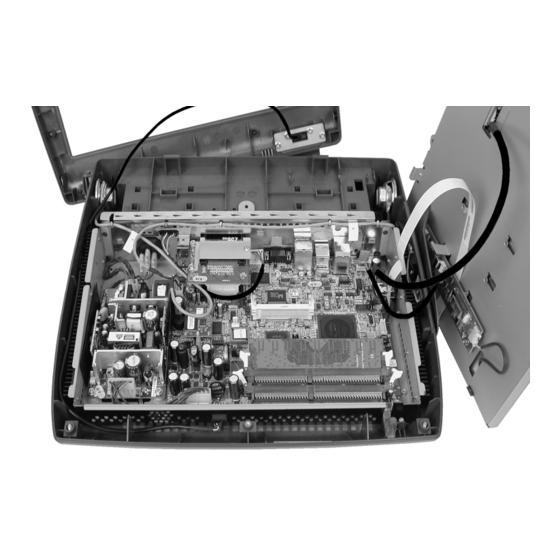
Remove and Replace the Workstation 5 FRUs Disassembling the Workstation 5 Disassembling the Workstation 5 The following procedure describes how to disassemble the workstation and access the system board and other internal components. SHOCK HAZARD Always remove the AC power cable from the unit before you open the cover. - Page 115 Remove and Replace the Workstation 5 FRUs Disassembling the Workstation 5 Remove the single screw that fastens the LCD and Touchscreen assembly to the base as shown at the top of Figure 4-2, below. Lift the assembly out of the base, placing it to the right of the base. Should you encounter resistance when lifting the LCD assembly - check to see if a cable has become snagged under the Mini-PCI connector.
- Page 116 To replace the Touchscreen Glass, LCD Panel or Backlight Inverter Board, refer to page 4-8. To remove and replace the Workstation 5 System Board, see page 4-17. To remove and replace the integrated LCD Customer Display, See page 4-26. Workstation 5 Field Service Guide...
-
Page 117: Magnetic Card Reader
Remove and Replace the Workstation 5 FRUs Magnetic Card Reader Magnetic Card Reader The procedure below describes how to remove and replace the Magnetic Card Reader. The Mag Stripe Reader FRU is a complete assembly, ready to install. Removal Remove the LCD/Touchscreen assembly as previously described. - Page 118 Remove and Replace the Workstation 5 FRUs Magnetic Card Reader Installation Orient the modular connector with the tab facing upwards, then push it through the cut-out in the side of the chassis to CN14. Figure 4-5 shows how to use a screw driver to guide the modular connector into place.
-
Page 119: The Power Supply
Remove and Replace the Workstation 5 FRUs The Power Supply The Power Supply The procedure describes how to remove and replace the Workstation 5 power supply. SHOCK HAZARD Be sure the AC Power Cable is disconnected from the unit before proceeding. -
Page 120: Lcd/Touchscreen Procedures
Remove and Replace the Workstation 5 FRUs LCD/Touchscreen Procedures LCD/Touchscreen Procedures This section contains procedures for changing the resistive or capacitive touchscreen glass, LCD Panel, and Backlight Inverter Board. Figure 4-7, below displays an exploded view of the LCD/Touchscreen assembly components. - Page 121 Remove and Replace the Workstation 5 FRUs LCD/Touchscreen Procedures Figure 4-8 below, represents the standard Resistive LCD/Touchscreen assembly showing the Backlight Inverter Board and interface cables. The resistive touchscreen ribbon cable and inverter board interface cable terminate on the system board.
-
Page 122: Touchscreen
Remove and Replace the Workstation 5 FRUs LCD/Touchscreen Procedures Touchscreen Removal This procedure applies to both the resistive and optional capacitive touchscreen glass. Refer to Figure 4-10, and work from the top towards the bottom of the illustration. Figure 4-10: Removing the Touchscreen Place the assembly face down and remove the touchscreen ribbon cable from the cable guide under the Backlight Inverter Board. - Page 123 Remove and Replace the Workstation 5 FRUs LCD/Touchscreen Procedures Installation Orient the touchscreen glass with the touch sensitive surface and cable on the top side as shown below. Figure 4-11: Touchscreen Orientation Place the glass panel in the bracket as shown at the bottom of Figure 4-10 then rotate downward until the clip locks the glass in place.
-
Page 124: Lcd Panel
Remove and Replace the Workstation 5 FRUs LCD/Touchscreen Procedures LCD Panel Removal Figure 4-12 below shows three how to remove the LCD Panel from the LCD/Touchscreen assembly. Figure 4-12: Removing the LCD Panel Place assembly face down. Remove (2) Backlight Inverter Cables from the Backlight Inverter Board, and the LCD Data Cable from the LCD Panel. - Page 125 Remove and Replace the Workstation 5 FRUs LCD/Touchscreen Procedures Installation Place the LCD Bracket around the replacement LCD Panel as shown in the Figure 4-13 below. Figure 4-13: Installing the LCD Panel Workstation 5 Field Service Guide 4-13...
- Page 126 Remove and Replace the Workstation 5 FRUs LCD/Touchscreen Procedures For the remaining steps, refer the lower section of Figure 4-13, on the previous page. Note the LCD panel maker. It will be from Sharp or AUO. Feed each backlight cable through the cut-outs in the LCD Plate, then fit the LCD/Touchscreen Bracket assembly inside the LCD Plate.
-
Page 127: Backlight Inverter Board
Remove and Replace the Workstation 5 FRUs LCD/Touchscreen Procedures Backlight Inverter Board The Backlight Inverter Board is attached to the LCD Plate with two screws. Place the LCD/Touchscreen Assembly face down to access the Backlight Inverter Board. Refer to Figure 4-15 and remove the Backlight Cables. Remove the pair of screws to remove the board. -
Page 128: Capacitive Touchscreen Interface Board
Remove and Replace the Workstation 5 FRUs LCD/Touchscreen Procedures Capacitive Touchscreen Interface Board The Capacitive Touchscreen Interface Board option is mounted to the rear of the LCD Plate. Place the LCD/Touchscreen assembly face down to access the Capacitive Interface Board Refer to Figure 4-16, below and remove the touchscreen ribbon cable from J1 and the system board interface from J2. -
Page 129: The System Board
Remove and Replace the Workstation 5 FRUs The System Board The System Board The following contains a procedure to remove and replace the Workstation 5 System Board. See page 4-2 to remove the Top Cover and LCD/Touchscreen Assembly. Refer to Figure 4-17, below and remove the items listed below. - Page 130 Remove and Replace the Workstation 5 FRUs The System Board Refer to Figure 4-18, and remove the system board mounting hardware. This includes three stand-offs and four screws. Figure 4-18: Removing the System Board Hardware Remove the board by lifting up the front of the board until it clears the chassis.
- Page 131 Remove and Replace the Workstation 5 FRUs The System Board Install the replacement system board in the chassis. Install the power button actuator assembly in the base and tighten the shoulder screw. Do not overtighten. Install the system board mounting hardware, but do not fasten. Position the System Board so that SW2 just touches the actuator as shown in the illustration.
-
Page 132: Usb Flash Drive
Remove and Replace the Workstation 5 FRUs The System Board USB Flash Drive This procedure describes how to remove and replace a USB Flash Drive. Remove the USB Flash Drive Remove the LCD/Touchscreen assembly as previously described. Refer to Figure 4-20, below. Use a pair of needle nose pliers to pinch the stand-off and remove the USB Flash Drive from J9. -
Page 133: Ddr Memory
Remove and Replace the Workstation 5 FRUs The System Board DDR Memory This section describes how to remove or replace a DDR DIMM. STATIC SENSITIVE DEVICES Always follow ESD procedures when installing or removing DIMMs. Refer to Figure 4-22, below. Rotate each retention clip away from the socket. -
Page 134: Approved Dimms
Remove and Replace the Workstation 5 FRUs The System Board Approved DIMMs for the Workstation 5 System Board Figure 4-24 lists the DDR DIMMs currently approved for use on the Workstation 5 System Board.. Size MICROS P/N Description 256MB 700502-175... -
Page 135: Bios Eeprom
The System Board BIOS EEPROM The Workstation 5 System Board BIOS EEPROM is located in a 32-pin PLCC socket, U38. MICROS recommends that you use a chip removal tool similar to that shown in the illustration below. This type of tool allows removal of the chip without damage to the socket. -
Page 136: Mini-Pci Wireless Card
Remove and Replace the Workstation 5 FRUs The System Board Mini-PCI Wireless Card This section describes how to remove the wireless card and move it to a different new. Two cards, the obsolete EZAIX or replacement Abocom may be found. - Page 137 Remove and Replace the Workstation 5 FRUs The System Board Install the antennae cables. Note that the Main and Aux connectors are reversed between the two boards. Figure 4-29, below. Figure 4-29: Installing the Wireless Card Antennae The Abocom wireless card requires GR1.2 or later to function.
-
Page 138: The Integrated Lcd Customer Display
Remove and Replace the Workstation 5 FRUs The Integrated LCD Customer Display The Integrated LCD Customer Display This procedure describes how to remove and replace the Integrated LCD Customer Display. Remove the AC power cable from the unit. Place a towel or soft cloth on your work surface to protect the LCD and touchscreen, then place the workstation face down on this surface. -
Page 139: Reassembling The Workstation 5
Reassembling the Workstation 5 Reassembling the Workstation 5 The following procedure describes how to reassemble the Workstation 5. If the optional Integrated Fingerprint Reader or other option is installed in the top cover, refer to Figure 4-31, below and connect the interface cable to J10. - Page 140 Remove and Replace the Workstation 5 FRUs Reassembling the Workstation 5 Resistive Touchscreen The standard resistive touchscreen configuration and jumper settings are shown on the left side of Figure 4-32. Connect the LCD Data cable to J8, the Backlight Inverter Cable to J3, and the resistive touchscreen ribbon cable from J6.
- Page 141 Remove and Replace the Workstation 5 FRUs Reassembling the Workstation 5 Install the LCD/Touchscreen Assembly in the base. The upper section of Figure 4-33, shows the rear of the assembly and corresponding slots in the base. Insert the LCD/Touchscreen Assembly at the angle shown then rotate down.
- Page 142 Install the cover by attaching it to the hook at the rear of the base first, then snapping the front of the cover into place. Figure 4-34: Installing the Workstation 5 Top Cover Tighten the captive screws to secure the cover. If a Fingerprint Reader or other option is installed in the top cover, avoid placing the unit on the housing while fasten the screws on the underside of the base.
-
Page 143: Connector And Cable Diagrams
Appendix B Connector and Cable Diagrams On the pages that follow, you will find diagrams of the Workstation 5 I/O Panel connectors, system board connectors, and commonly used hook-up cables. A description of how each cable or connector is used is provided. -
Page 144: Io Panel Connectors
Connector and Cable Diagrams IO Panel Connectors IO Panel Connectors The following connectors are located on the Workstation 5 IO Panel. IDN Port The IDN connector is a combination RS422/RS232 port associated with COM4. This port is functionally equivalent to the RS422-A and RS422-B ports on the WS4 or WS4 LX. - Page 145 The COM5 connector is a full-featured RS232 modular COM port similar to that found on the PCWS Eclipse and 2010. Use cable P/N 300319-103 to convert this port to a DB9 connector. Figure B-3: COM5 Modular RS232 Connector Workstation 5 Setup Guide...
-
Page 146: Rs232 Connector
IO Panel Connectors RS232 Connector A single DB9F RS232 connector assigned to COM1 is provided. The pin-out is shown below. Figure B-4: DB9 RS232 Connector Diagram Cash Drawer 1 and 2 Connectors Figure B-5: Cash Drawer Connector Diagram Workstation 5 Setup Guide... -
Page 147: Remote Customer Display Connector
Connector and Cable Diagrams IO Panel Connectors Remote Customer Display Connector This port supports either the 2x20 VFD customer display or the graphics based LCD customer display. Figure B-6: Customer Display Connector Diagram Workstation 5 Setup Guide... -
Page 148: System Board Connectors
Connector and Cable Diagrams System Board Connectors System Board Connectors This section details connectors located on the Workstation 5 system board. Magnetic Stripe Interface The internal magnetic card reader connector is CN14, located on the system board. The pin-outs for this connector are shown in Figure B-7,... -
Page 149: Hook-Up Cables
Hook-up Cables Hook-up Cables The following pages show wiring diagrams of various hook-up cables that may be used with the Workstation 5. IDN Port RS232 Cables Figure B-8 displays a cable that includes the RS232 signals from the IDN Port to a DB9 male connector. - Page 150 Board, mounting bracket and interface cable. A diagram of this interface cable is shown in Figure B-11. When the LCD Customer Display is attached directly to the Workstation 5, this cable plugs into the ‘Rear Display’ IO Panel connector shown in Figure B-13.
- Page 151 The cable shown in Figure B-12 is supplied with the Pole LCD Customer Display or Adjustable Stand Pole Display kit. It attaches between the 4-pin Mini-DIN connector on the Workstation 5 I/O panel, through the pole to mate with the cable from the LCD Customer Display Housing Cable shown in Figure B-11.
-
Page 152: Ethernet
Figure B-14 shows a diagram of a standard Cat 5 Ethernet hook-up cable. This cable would be connected from a workstation or server to the system hub. Figure B-14: EIA/TIA-568-A Cat 5 Ethernet Hook-up Cable Diagram B-10 Workstation 5 Setup Guide... - Page 153 This cable can be used when only two devices must be connected. For example, it can be used to connect two workstations, or a server connected to a single client. Figure B-15: Cat 5 Ethernet Hook-up Cable Diagram (cross-over) Workstation 5 Setup Guide B-11...
-
Page 154: 8-Pin To 6-Pin Hook-Up Rs422 Cable (300319-001
This cable brings out the RS422 signals from the IDN port connector to a 6-pin wall plate connector or directly to the IDN connector on the printing device. Figure B-16: 8-Pin to 6-Pin IDN Hook-up Cable Diagram B-12 Workstation 5 Setup Guide... -
Page 155: Cash Drawer Extension Cable
Connector and Cable Diagrams Hook-up Cables Cash Drawer Extension Cable Workstation 5 Setup Guide B-13... - Page 156 Connector and Cable Diagrams Hook-up Cables B-14 Workstation 5 Setup Guide...
Need help?
Do you have a question about the Workstation 5 and is the answer not in the manual?
Questions and answers