IBM System x3350 Type 4192 Problem Determination And Service Manual
Type 4192 and 4193
Hide thumbs
Also See for System x3350 Type 4192:
- User manual (98 pages) ,
- Installation manual (84 pages) ,
- Product manual (16 pages)
Table of Contents
Advertisement
Quick Links
Advertisement
Table of Contents

Related Manuals for IBM System x3350 Type 4192


Summary of Contents for IBM System x3350 Type 4192
- Page 1 IBM System x3350 Type 4192 and 4193 Problem Determination and Service Guide...
- Page 3 IBM System x3350 Type 4192 and 4193 Problem Determination and Service Guide...
- Page 4 Note: Before using this information and the product it supports, read the general information in Appendix B, “Notices,” on page 225 and the Warranty and Support Information document on the IBM System x Documentation CD. Third Edition (March 2009) © Copyright International Business Machines Corporation 2008, 2009.
-
Page 5: Table Of Contents
Configuring the Broadcom NetXtreme Gigabit Ethernet controller ..41 Updating IBM Director ..... 42 Setting up a Remote Supervisor Adapter II SlimLine ..42 Chapter 3. - Page 6 General problems ..... . 134 Hard disk drive problems....134 IBM System x3350 Type 4192 and 4193: Problem Determination and Service Guide...
- Page 7 Hardware service and support ....224 IBM Taiwan product service ....224 Appendix B.
- Page 8 IBM System x3350 Type 4192 and 4193: Problem Determination and Service Guide...
-
Page 9: Safety
Les sikkerhetsinformasjonen (Safety Information) før du installerer dette produktet. Antes de instalar este produto, leia as Informações sobre Segurança. Antes de instalar este producto, lea la información de seguridad. Läs säkerhetsinformationen innan du installerar den här produkten. © Copyright IBM Corp. 2008, 2009... -
Page 10: Guidelines For Trained Service Technicians
Use the information in this section to help you identify potential unsafe conditions in an IBM product that you are working on. Each IBM product, as it was designed and manufactured, has required safety items to protect users and service technicians from injury. - Page 11 v Do not touch the reflective surface of a dental mirror to a live electrical circuit. The surface is conductive and can cause personal injury or equipment damage if it touches a live electrical circuit. v Some rubber floor mats contain small conductive fibers to decrease electrostatic discharge.
-
Page 12: Safety Statements
Be sure to read all caution and danger statements in this documentation before you perform the procedures. Read any additional safety information that comes with the server or optional device before you install the device. IBM System x3350 Type 4192 and 4193: Problem Determination and Service Guide... - Page 13 Statement 1: DANGER Electrical current from power, telephone, and communication cables is hazardous. To avoid a shock hazard: v Do not connect or disconnect any cables or perform installation, maintenance, or reconfiguration of this product during an electrical storm. v Connect all power cords to a properly wired and grounded electrical outlet.
- Page 14 Statement 2: CAUTION: When replacing the lithium battery, use only IBM Part Number 33F8354 or an equivalent type battery recommended by the manufacturer. If your system has a module containing a lithium battery, replace it only with the same module type made by the same manufacturer.
- Page 15 Statement 3: CAUTION: When laser products (such as CD-ROMs, DVD drives, fiber optic devices, or transmitters) are installed, note the following: v Do not remove the covers. Removing the covers of the laser product could result in exposure to hazardous laser radiation. There are no serviceable parts inside the device.
- Page 16 The device also might have more than one power cord. To remove all electrical current from the device, ensure that all power cords are disconnected from the power source. IBM System x3350 Type 4192 and 4193: Problem Determination and Service Guide...
- Page 17 Statement 8: CAUTION: Never remove the cover on a power supply or any part that has the following label attached. Hazardous voltage, current, and energy levels are present inside any component that has this label attached. There are no serviceable parts inside these components.
- Page 18 IBM System x3350 Type 4192 and 4193: Problem Determination and Service Guide...
-
Page 19: Chapter 1. Introduction
Replaceable components are of three types: v Tier 1 customer replaceable unit (CRU): Replacement of Tier 1 CRUs is your responsibility. If IBM installs a Tier 1 CRU at your request, you will be charged for the installation. v Tier 2 customer replaceable unit: You may install a Tier 2 CRU yourself or request IBM to install it, at no additional charge, under the type of warranty service that is designated for your server. -
Page 20: Notices And Statements In This Document
These updates are available from the IBM Web site. To check for updated documentation and technical updates, complete the following steps. -
Page 21: Features And Specifications
Features and specifications The following information is a summary of the features and specifications of the server. Depending on the server model, some features might not be available, or some specifications might not apply. Chapter 1. Introduction... - Page 22 – Server on: 8% to 80% levels indicate an upper limit, below – Server off: 8% to 80% which a large number of computers will operate. IBM System x3350 Type 4192 and 4193: Problem Determination and Service Guide...
-
Page 23: Server Controls, Leds, And Connectors
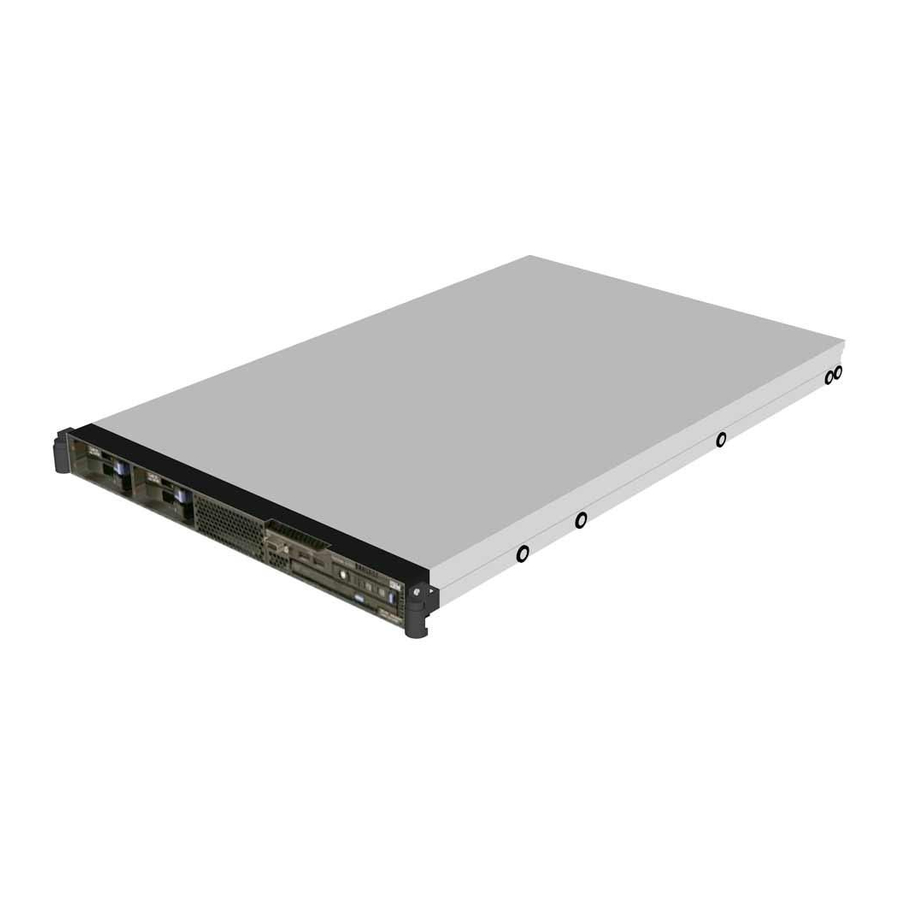
Server controls, LEDs, and connectors This section describes the controls, light-emitting diodes (LEDs), and connectors on the front and rear of the server. Front view The following illustration shows the 2.5-inch hard disk drive server model. USB 3 connector Operator information USB 4 connector Rack release latch panel... - Page 24 – System-locator LED: Use this blue LED to visually locate the server among other servers. You can use IBM Director to light this LED remotely. This LED is controlled by the BMC. – System-error LED: When this amber LED is lit, it indicates that a system error has occurred.
-
Page 25: Rear View
LED itself has failed. v System-locator LED: Use this LED to visually locate the server among other servers. You can use IBM Director to light this LED remotely. v Video connector: Connect a monitor to this connector. The video connectors on the front and rear of the server can be used simultaneously. -
Page 26: Internal Leds, Connectors, And Jumpers
(some models) Mini-SAS/SATA controller connector Microprocessor connector IDE connector Fan 2 connector Operator information panel connector Fan 5 connector Video connector Fan 4 connector USB connectors Fan 3 connector IBM System x3350 Type 4192 and 4193: Problem Determination and Service Guide... -
Page 27: Power Backplane Card Internal Connectors
Power backplane card internal connectors The following illustration shows the internal connectors on the power backplane card. Power-supply connectors System-board connector Hard disk drive power connector Chapter 1. Introduction... -
Page 28: System-Board Switches And Jumpers
Pins 2 and 3: Clear the CMOS data, which clears the power-on password and administrator password Boot block recovery (JP4) v Pins 1 and 2: Normal (default). v Pins 2 and 3: Recover boot block IBM System x3350 Type 4192 and 4193: Problem Determination and Service Guide... -
Page 29: System-Board External Connectors
System-board external connectors The following illustration shows the external connectors on the system board. Ethernet connector USB 1 connector Systems- management USB 2 connector Ethernet 2 connector Serial connector Ethernet 1 connector Video connector Chapter 1. Introduction... -
Page 30: System-Board Leds
Fan 2 error LED DIMM 1 error DIMM 2 error Fan 5 error LED DIMM 3 error Fan 4 error LED DIMM 4 error Fan 3 error LED IBM System x3350 Type 4192 and 4193: Problem Determination and Service Guide... -
Page 31: System-Board Optional-Device Connectors
System-board optional-device connectors The following illustration shows the connectors for user-installable options. PCI Express or optional PCI Express or optional SAS/SATA controller SAS/SATA controller connector 2 connector Remote Supervisor Adapter II SlimLine connector Mini - SAS/SATA controller connector DIMM connector 1 DIMM connector 2 DIMM connector 3 DIMM connector 4... - Page 32 IBM System x3350 Type 4192 and 4193: Problem Determination and Service Guide...
-
Page 33: Chapter 2. Configuration Information And Instructions
Updating the firmware The firmware in the server is periodically updated and is available for download on the Web. Go to http://www.ibm.com/systems/support/ to check for the latest level of firmware, such as BIOS code, device drivers, and service processor firmware. -
Page 34: Using The Configuration/Setup Utility Program
IBM Director IBM Director is a workgroup-hardware-management tool that you can use to centrally manage System x servers. If you plan to use IBM Director to manage the server, you must check for the latest applicable IBM Director update and interim fixes. - Page 35 Configuration/Setup Utility menu choices The following choices are on the Configuration/Setup Utility main menu. Depending on the version of the BIOS code, some menu choices might differ slightly from these descriptions. v System Summary Select this choice to view configuration information, including the amount of installed memory.
- Page 36 Select this choice to view the system resources that are used by installed PCI Express devices, configure PCI interrupt routing, and enable or disable PCI ROM Control Execution. IBM System x3350 Type 4192 and 4193: Problem Determination and Service Guide...
- Page 37 – RSA II Settings Select this choice to view and change Remote Supervisor Adapter II SlimLine settings. Select Save Values and Reboot RSA II to save the changes that you make in the settings and restart the Remote Supervisor Adapter II SlimLine.
- Page 38 Select Clear System Logs to clear the system event/error log. – RSA II Event/Error Log This choice is available only if an optional Remote Supervisor Adapter II SlimLine is installed. IBM System x3350 Type 4192 and 4193: Problem Determination and Service Guide...
- Page 39 Select this choice to view the error messages in the Remote Supervisor Adapter II event/error log. Use the arrow keys to move among pages in the log. Select Clear RSA II logs to clear the Remote Supervisor Adapter II event/error log. The Remote Supervisor Adapter II event/error log contains all event and error messages that have been generated during POST, by the system interface handler, and by the system service processor.
- Page 40 CMOS jumper on the system board to pins 2 and 3 to clear CMOS memory and bypass the power-on or administrator password check. The jumper location is shown in the following illustration. IBM System x3350 Type 4192 and 4193: Problem Determination and Service Guide...
-
Page 41: Using The Boot Menu Program
Boot block recovery (JP4) Clear CMOS (JP1) To clear CMOS memory and reset the passwords, complete the following steps: 1. Review the safety information that begins on page vii. 2. Turn off the server and peripheral devices and disconnect all power cords and external cables. -
Page 42: Using The Serverguide Setup And Installation Cd
When you use the ServerGuide Setup and Installation CD, you do not need setup diskettes. You can use the CD to configure any supported IBM server model. The setup program provides a list of tasks that are required to set up your server model. -
Page 43: Installing Your Operating System Without Using Serverguide
ServerGuide program to install your operating system, complete the following steps to download the latest operating-system installation instructions from the IBM Web site. Note: Changes are made periodically to the IBM Web site. The actual procedure might vary slightly from what is described in this document. 1. Go to http://www.ibm.com/systems/support/. -
Page 44: Using The Lsi Logic Configuration Utility Program
Starting the LSI Logic Configuration Utility program To start the LSI Logic Configuration Utility program, complete the following steps: 1. Turn on the server. IBM System x3350 Type 4192 and 4193: Problem Determination and Service Guide... -
Page 45: Using The Baseboard Management Controller
2. When the prompt Press CTRL-C to start LSI Logic Configuration Utility..is displayed, press Ctrl+C. If you have set an administrator password, you are prompted to type the password. 3. To select a controller (channel) from the list of adapters, use the arrow keys and press Enter. -
Page 46: Enabling And Configuring Sol Using The Osa Smbridge Management Utility Program
Select Advanced Setup; then, select Baseboard Management Controller (BMC) Settings. f. Select System-BMC Serial Port Sharing and set it to Enabled. g. Select BMC Serial Port Access Mode and set it to Shared. IBM System x3350 Type 4192 and 4193: Problem Determination and Service Guide... - Page 47 h. Press Esc to exit the BMC Serial Port Access Mode section of the Baseboard Management Controller (BMC) Settings. i. Press Esc to exit Baseboard Management Controller (BMC) Settings. j. Select Save Settings; then, press Enter. k. Press Enter to continue. l.
- Page 48 The following examples show the original content of the /etc/lilo.conf file and the content of this file after modification. Original /etc/lilo.conf contents prompt timeout=50 default=linux boot=/dev/hda map=/boot/map install=/boot/boot.b message=/boot/message linear image=/boot/vmlinuz-2.4.9-e.12smp label=linux initrd=/boot/initrd-2.4.9-e.12smp.img read-only root=/dev/hda6 image=/boot/vmlinuz-2.4.9-e.12 label=linux-up initrd=/boot/initrd-2.4.9-e.12.img read-only root=/dev/hda6 IBM System x3350 Type 4192 and 4193: Problem Determination and Service Guide...
- Page 49 Modified /etc/lilo.conf contents prompt timeout=50 default=linux-Monitor boot=/dev/hda #map=/boot/map install=/boot/boot.b #message=/boot/message linear # This will allow you to only Monitor the OS boot via SOL image=/boot/vmlinuz-2.4.9-e.12smp label=linux-Monitor initrd=/boot/initrd-2.4.9-e.12smp.img read-only root=/dev/hda6 append="console=ttyS0,19200n8 console=tty1" # This will allow you to Interact with the OS boot via SOL image=/boot/vmlinuz-2.4.9-e.12smp label=linux-Interact initrd=/boot/initrd-2.4.9-e.12smp.img...
- Page 50 Red Hat Enterprise Linux ES (2.4.9-e.12smp) root (hd0,0) kernel /vmlinuz-2.4.9-e.12smp ro root=/dev/hda6 initrd /initrd-2.4.9-e.12smp.img title Red Hat Enterprise Linux ES-up (2.4.9-e.12) root (hd0,0) kernel /vmlinuz-2.4.9-e.12 ro root=/dev/hda6 initrd /initrd-2.4.9-e.12.img IBM System x3350 Type 4192 and 4193: Problem Determination and Service Guide...
- Page 51 Modified /boot/grub/grub.conf contents #grub.conf generated by anaconda # Note that you do not have to rerun grub after making changes to this file # NOTICE: You have a /boot partition. This means that all kernel and initrd paths are relative to /boot/, eg. root (hd0,0) kernel /vmlinuz-version ro root=/dev/hda6 initrd /initrd-version.img...
- Page 52 # This will allow you to Interact with the OS boot via SOL title linux SOL Interactive kernel (hd0,1)/boot/vmlinuz root=/dev/hda2 acpi=oldboot vga=791 console=tty1 console=ttyS0,19200 initrd (hd0,1)/boot/initrd title floppy IBM System x3350 Type 4192 and 4193: Problem Determination and Service Guide...
- Page 53 Modified /boot/grub/menu.lst contents Notes root chainloader +1 title failsafe kernel (hd0,1)/boot/vmlinuz.shipped root=/dev/hda2 ide=nodma apm=off vga=normal nosmp disableapic maxcpus=0 3 initrd (hd0,1)/boot/initrd.shipped Note 1: The kernel line is shown with a line break. In your file, the entire entry must all be on one line. You must restart the Linux operating system after you complete these procedures for the changes to take effect and to enable SOL.
-
Page 54: Installing The Osa Smbridge Management Utility Program
OSA BMC Management Utility CD. 2. Insert the OSA BMC Management Utility CD into the drive. The InstallShield wizard starts, and a window similar to that shown in the following illustration opens. IBM System x3350 Type 4192 and 4193: Problem Determination and Service Guide... - Page 55 Linux operating system. You must be logged in as a root user to perform these procedures. 1. Go to http://www.ibm.com/systems/support/. Download the utility program and create the OSA BMC Management Utility CD. 2. Insert the OSA BMC Management Utility CD into the drive.
-
Page 56: Using The Baseboard Management Controller Utility Programs
2. Under Product support, click System x. 3. Under Popular links, click Software and device drivers. 4. Click IBM System x3350 to display the matrix of downloadable files for the server. 5. From the BMC software, copy the files bmc.exe and Init.ini to a setup utility diskette. - Page 57 2. Under Product support, click System x. 3. Under Popular links, click Software and device drivers. 4. Click IBM System x3350 to display the matrix of downloadable files for the server. 5. From the BMC software, copy the file bmc_cfg.exe to a configuration utility diskette.
- Page 58 2. Under Product support, click System x. 3. Under Popular links, click Software and device drivers. 4. Click IBM System x3350 to display the matrix of downloadable files for the server. 5. From the BMC software, copy the file fsloader.exe to an SDR/FRU update diskette.
-
Page 59: Enabling The Broadcom Gigabit Ethernet Utility Program
1. Go to http://www.ibm.com/systems/support/ 2. Under Product support, click System x. 3. Under Popular links, click Software and device drivers. 4. Click IBM System x3350 to display the matrix of downloadable device driver files for the server. Chapter 2. Configuration information and instructions... -
Page 60: Updating Ibm Director
Updating IBM Director If you plan to use IBM Director to manage the server, you must check for the latest applicable IBM Director updates and interim fixes. To install the IBM Director updates and any other applicable updates and interim fixes, complete the following steps. -
Page 61: Cabling The Remote Supervisor Adapter Ii Slimline
Firmware-update utility program To download and install the software and firmware, complete the following steps. Note: Changes are made periodically to the IBM Web site. The actual procedure might vary slightly from what is described in this document. 1. Go to http://www.ibm.com/systems/support/. -
Page 62: Completing The Setup
4. Click System x3350 to display the matrix of downloadable files for the server. 5. Select the software or firmware package that you want to install. On the next page, click the link for each file that you want to download. Follow the instructions that are displayed. -
Page 63: Chapter 3. Parts Listing, System X3350 Type 4192 And 4193 Server
4193 servers. For an updated parts listing on the Web, complete the following steps. Note: Changes are made periodically to the IBM Web site. the actual procedure might vary slightly from what is described in this document. 1. Go to http://www.ibm.com/systems/support/ 2. - Page 64 IBM System x3350 Type 4192 and 4193: Problem Determination and Service Guide...
-
Page 65: Replaceable Server Components
Replaceable components are of three types: v Tier 1 customer replaceable unit (CRU): Replacement of Tier 1 CRUs is your responsibility. If IBM installs a Tier 1 CRU at your request, you will be charged for the installation. v Tier 2 customer replaceable unit: You may install a Tier 2 CRU yourself or request IBM to install it, at no additional charge, under the type of warranty service that is designated for your server. - Page 66 39M4375 B2x) (type 4193 models 44x, 52x, B2x, E5x) Simple-swap filler panel, 3.5-inch (type 4192 models 32x, 39M4343 42x, B4x, E1x, E3x) (type 4193 models 32x, 42x, B4x) IBM System x3350 Type 4192 and 4193: Problem Determination and Service Guide...
- Page 67 DVD-drive, Rambo 4.5 (optional) 39M3567 DVD-drive, RAM Rambo 5 (optional) 42C0955 DVD-drive, RAM Rambo 5 (optional) 42C0959 PCI-E 4 GB single port fiber channel host bus adapter 39R6526 (optional) Chapter 3. Parts listing, System x3350 Type 4192 and 4193 server...
- Page 68 NetXtreme II 1000 express dual port ethernet adapter 42C1782 (optional) NetXtreme II 10 GB express fiber SR adapter (optional) 42C1792 PRO/1000 PT dual port server adapter (optional) 39Y6128 IBM System x3350 Type 4192 and 4193: Problem Determination and Service Guide...
-
Page 69: Product Recovery Cds
Edition 1-4 Processors Japanese Microsoft Windows Server 2003 R2 w/SP2 32bit Standard 44W4053 Edition 1-4 Processors Simplified Chinese Microsoft Windows Server 2003 R2 w/SP2 32bit Standard 44W4054 Edition 1-4 Processors Korean Chapter 3. Parts listing, System x3350 Type 4192 and 4193 server... - Page 70 Edition 1-2 Processors Japanese Microsoft Windows Server 2003 R2 w/SP2 Enterprise x64 44W4076 Edition 1-8 Processors English Microsoft Windows Server 2003 R2 w/SP2 Enterprise x64 44W4077 Edition 1-8 Processors Japanese IBM System x3350 Type 4192 and 4193: Problem Determination and Service Guide...
-
Page 71: Power Cords
1-8 Processor Traditional Chinese Power cords For your safety, IBM provides a power cord with a grounded attachment plug to use with this IBM product. To avoid electrical shock, always use the power cord and plug with a properly grounded outlet. - Page 72 Micronesia (Federal States of), Netherlands Antilles, Nicaragua, Panama, Peru, Philippines, Saudi Arabia, Thailand, Taiwan, United States of America, Venezuela 39M5219 Korea (Democratic People’s Republic of), Korea (Republic of) 39M5199 Japan IBM System x3350 Type 4192 and 4193: Problem Determination and Service Guide...
- Page 73 IBM power cord part number Used in these countries and regions 39M5068 Argentina, Paraguay, Uruguay 39M5226 India 39M5233 Brazil Chapter 3. Parts listing, System x3350 Type 4192 and 4193 server...
- Page 74 IBM System x3350 Type 4192 and 4193: Problem Determination and Service Guide...
-
Page 75: Chapter 4. Removing And Replacing Server Components
Replaceable components are of three types: v Tier 1 customer replaceable unit (CRU): Replacement of Tier 1 CRUs is your responsibility. If IBM installs a Tier 1 CRU at your request, you will be charged for the installation. v Tier 2 customer replaceable unit: You may install a Tier 2 CRU yourself or request IBM to install it, at no additional charge, under the type of warranty service that is designated for your server. -
Page 76: System Reliability Guidelines
When you are finished working on the server, reinstall all safety shields, guards, labels, and ground wires. v For a list of supported optional devices for the server, see http://www.ibm.com/ servers/eserver/serverproven/compat/us/. System reliability guidelines... -
Page 77: Working Inside The Server With The Power On
Working inside the server with the power on Attention: Static electricity that is released to internal server components when the server is powered-on might cause the server to halt, which might result in the loss of data. To avoid this potential problem, always use an electrostatic-discharge wrist strap or other grounding system when you work inside the server with the power on. -
Page 78: Connecting The Cables
USB 3 connector USB 4 connector Video connector Rear View Power-supply connector Ethernet 1 Video connector USB 2 Ethernet 2 USB 1 Systems- Serial management Ethernet connector connector IBM System x3350 Type 4192 and 4193: Problem Determination and Service Guide... -
Page 79: Removing And Replacing Tier 1 Crus
Removing and replacing Tier 1 CRUs Replacement of Tier 1 CRUs is your responsibility. If IBM installs a Tier 1 CRU at your request, you will be charged for the installation. The illustrations in this document might differ slightly from your hardware. -
Page 80: Installing The Cover
4. Tighten the thumbscrew until the cover correctly engages all the inset tabs on the server. Thumbscrew Fan door 5. Slide the server into the rack. IBM System x3350 Type 4192 and 4193: Problem Determination and Service Guide... -
Page 81: Removing The Side Air Baffle
Removing the side air baffle To remove the air baffle that is closest to the wall of the server, complete the following steps: 1. Read the safety information that begins on page vii and “Installation guidelines” on page 57. 2. Turn off the server and peripheral devices and disconnect all power cords and external cables. -
Page 82: Removing The Center Air Baffle
57. 2. Turn off the server and peripheral devices and disconnect all power cords and external cables. 3. Remove the cover (see “Removing the cover” on page 61). IBM System x3350 Type 4192 and 4193: Problem Determination and Service Guide... -
Page 83: Installing The Center Air Baffle
Air baffle Baffle pins Cable routing slot Baffle mounting holes 4. Lift the baffle up slightly, making sure that the pins come out of the holes on the system board. 5. Slide the cable out of the cable routing slot. Make sure that you do not disconnect or loosen the cable. -
Page 84: Removing A Riser-Card Assembly
3. Remove the cover (see “Removing the cover” on page 61). 4. If an adapter is installed in the riser-card assembly, disconnect any cables that are connected to the adapter. IBM System x3350 Type 4192 and 4193: Problem Determination and Service Guide... -
Page 85: Installing A Riser-Card Assembly
Expansion slot cover PCI Express adapter Adapter support bracket Expansion Riser-card slot assembly Riser-card connector 5. Grasp the riser-card assembly at the rear edge and lift to remove it. 6. If there is an adapter in the riser-card assembly, remove it. 7. -
Page 86: Removing An Adapter
8. If you are instructed to return the adapter, follow all packaging instructions, and use any packaging materials for shipping that are supplied to you. IBM System x3350 Type 4192 and 4193: Problem Determination and Service Guide... -
Page 87: Installing An Adapter
Installing an adapter To install the replacement adapter, complete the following steps. 1. Route the adapter cables, if any, before you install the adapter. Route the cables so that they are not on top of components or blocking the airflow from the fans. -
Page 88: Removing A Remote Supervisor Adapter Ii Slimline
1. Read the safety information that begins on page vii and “Installation guidelines” on page 57. 2. Position the Remote Supervisor Adapter II SlimLine so that the connector on the adapter aligns with the connector on the system board. IBM System x3350 Type 4192 and 4193: Problem Determination and Service Guide... - Page 89 Remote Supervisor Adapter II SlimLine Rear mounting bracket Front mounting bracket retention latch Front mounting bracket 3. At a downward angle, slip the back end of the adapter under the tab on the rear mounting bracket, aligning the holes in the adapter with the posts on the rear mounting bracket.
-
Page 90: Removing And Installing Internal Drives
6. Pull the drive out of the front of the server. 7. Remove the retention clip from the side of the drive. Save the clip to use when you install the replacement drive. Drive-retention clip Alignment pins IBM System x3350 Type 4192 and 4193: Problem Determination and Service Guide... - Page 91 8. If you are instructed to return the CD-RW/DVD drive, follow all packaging instructions, and use any packaging materials for shipping that are supplied to you. Installing the CD-RW/DVD drive To install the replacement CD-RW/DVD drive, complete the following steps: 1.
- Page 92 To avoid damage to the hard disk drive connectors, make sure that the server cover is in place and fully closed whenever you install or remove a hard disk drive. IBM System x3350 Type 4192 and 4193: Problem Determination and Service Guide...
-
Page 93: Installing A Hot-Swap Hard Disk Drive
The following illustration show the 2.5-inch hard disk drive server model. SAS hard disk drive backplane Drive-tray assembly Drive handle The following illustration shows the 3.5-inch hard disk drive server model. Hard disk drive assembly Drive handle 1. Read the safety information that begins on page vii and “Installation guidelines” on page 57. -
Page 94: Removing The Cd-Rw/Dvd Drive Interposer Card
2. Turn off the server and peripheral devices and disconnect the power cords and all external cables. 3. Open the fan door. 4. Remove the CD-RW/DVD drive (see “Removing a CD-RW/DVD drive” on page 72). IBM System x3350 Type 4192 and 4193: Problem Determination and Service Guide... -
Page 95: Installing The Cd-Rw/Dvd Drive Interposer Card
CD-RW/DVD drive cable retainer 5. Slide the CD-RW/DVD drive cable retainer away from the interposer card. Mounting screws Interposer card CD-RW/DVD drive 6. Remove the two mounting screws from the interposer card and disconnect the CD-RW/DVD drive cable; then, remove the interposer card. 7. -
Page 96: Removing A Memory Module (Dimm)
1. Read the safety information that begins on page vii and “Installation guidelines” on page 57. 2. Turn off the server and peripheral devices and disconnect the power cord and all external cables. IBM System x3350 Type 4192 and 4193: Problem Determination and Service Guide... -
Page 97: Installing A Memory Module (Dimm)
DIMMs: v The server supports up to four DIMMs for system memory. See http://www.ibm.com/servers/eserver/serverproven/compat/us/ for a list of memory modules that you can use with the server. Note: Because some memory is reserved for system operation, the actual usable memory size that is reported by the operating system is less than the total installed size. - Page 98 DIMM 4 Single-rank Single-rank Single-rank Single-rank Single-rank Single-rank Double-rank Double-rank Recommend this configuration as the first choice. Double-rank Double-rank Single-rank Single-rank Recommend this configuration as the second choice. IBM System x3350 Type 4192 and 4193: Problem Determination and Service Guide...
- Page 99 Table 6. Interleave Mode DIMM slot population (continued) First pair Second pair Remarks Double-rank Double-rank Double-rank Double-rank v When you install or remove DIMMs, the server configuration information changes. When you restart the server, the system displays a message that indicates that the memory configuration has changed.
-
Page 100: Removing An Optional Serveraid-Mr10I Sas/Sata Controller
2. Touch the static-protective package that contains the controller to any unpainted metal surface on the server. Then, remove the controller from the static-protective package. Avoid touching the components and gold-edge connectors on the controller. IBM System x3350 Type 4192 and 4193: Problem Determination and Service Guide... -
Page 101: Removing A Power Supply
Expansion- slot cover Optional ServeRAID-MR10i SAS/SATA controller Riser-card assembly Expansion slot Riser-card connector 3. Insert the controller into the riser-card assembly, aligning the connector on the controller with the connector on the riser-card assembly. Press the controller firmly into the riser-card assembly. Make sure that the controller snaps securely into the riser-card assembly. -
Page 102: Installing A Power Supply
6. If you are instructed to return the power supply, follow all packaging instructions, and use any packaging materials for shipping that are supplied to you. Installing a power supply Statement 8: IBM System x3350 Type 4192 and 4193: Problem Determination and Service Guide... -
Page 103: Removing A Hot-Swap Fan Assembly
CAUTION: Never remove the cover on a power supply or any part that has the following label attached. Hazardous voltage, current, and energy levels are present inside any component that has this label attached. There are no serviceable parts inside these components. -
Page 104: Installing A Hot-Swap Fan Assembly
To ensure proper server operation, replace a failed fan within 48 hours. To install the replacement hot-swap fan, complete the following steps: 1. Read the safety information that begins on page vii and “Installation guidelines” on page 57 IBM System x3350 Type 4192 and 4193: Problem Determination and Service Guide... -
Page 105: Removing The Battery
2. Orient the new fan in the same position as the fan that you removed. Make sure that the airflow indicator, on the top of the fan, is pointing to the rear of the server Fan 2 A IR A IR Fan 3 Fan 4 Fan 5... -
Page 106: Installing The Battery
Statement 2: CAUTION: When replacing the lithium battery, use only IBM Part Number 33F8354 or an equivalent type battery recommended by the manufacturer. If your system has a module containing a lithium battery, replace it only with the same module type made by the same manufacturer. -
Page 107: Removing And Replacing Tier 2 Crus
See “Using the Configuration/Setup Utility program” on page 16 for details. Removing and replacing Tier 2 CRUs You may install a Tier 2 CRU yourself or request IBM to install it, at no additional charge, under the type of warranty service that is designated for your server. - Page 108 5. Align the holes in the top of the drive cage with the holes in the top of the chassis; then, insert the screws that secure the drive cage to the chassis. IBM System x3350 Type 4192 and 4193: Problem Determination and Service Guide...
- Page 109 6. Install the removed drives (see “Removing and installing internal drives” on page 72). 7. Install the cover (see “Installing the cover” on page 62). 8. Slide the server into the rack. 9. Reconnect the external cables and the power cords. 10.
-
Page 110: Removing The Media Bezel
89). 5. Remove fan number 3 (see “Removing a hot-swap fan assembly” on page 85). 6. Disconnect the video cable from the connector on the system board. IBM System x3350 Type 4192 and 4193: Problem Determination and Service Guide... -
Page 111: Installing The Media Bezel
Mounting screws Video cable screws Media bezel 7. Remove the two mounting screws in the top of the media bezel. 8. Rotate the media bezel downward to disengage it from the chassis and carefully pull the video cable out of the server. Remove the cable and the bezel from the server. -
Page 112: Removing The Mini-Sas/Sata Controller (Hot-Swap Models)
To install the replacement mini-SAS/SATA controller, complete the following steps: 1. Read the safety information that begins on page vii and “Installation guidelines” on page 57 2. Grasp the edges of the SAS/SATA controller. IBM System x3350 Type 4192 and 4193: Problem Determination and Service Guide... - Page 113 Notches Mini-SAS/SATA controller 3. Gently insert the controller into the SAS/SATA controller connector on the system board (see “System-board internal connectors” on page 8 for the location of the connector) while you align the holes in the controller with the two plastic alignment pins on the system board.
-
Page 114: Removing The 3.5-Inch Sas/Sata Hot-Swap Backplane Or Sata Simple-Swap Backplate
Installing the 3.5-inch SAS/SATA hot-swap backplane or SATA simple-swap backplate To install the replacement 3.5-inch SAS/SATA hot-swap backplane or SAS simple-swap backplate, complete the following steps. IBM System x3350 Type 4192 and 4193: Problem Determination and Service Guide... -
Page 115: Removing The 2.5-Inch Sas Backplane
3.5-inch backplane/backplate Mounting channel Locking tab Mounting channel Drive bay 0 Drive bay 1 1. Read the safety information that begins on page vii and “Installation guidelines” on page 57. 2. Connect the power cable to the backplane or backplate. 3. -
Page 116: Installing The 2.5-Inch Sas Backplane
To install the replacement 2.5-inch SAS backplane, complete the following steps: Power cable 2.5 in. disk drive backplane Locking tab Mounting channel Signal cable Locking tab Mounting channel 2.5 in. disk drive cage IBM System x3350 Type 4192 and 4193: Problem Determination and Service Guide... -
Page 117: Removing A Sata Raid Backplate
1. Read the safety information that begins on page vii and “Installation guidelines” on page 57 2. Connect the power cable and signal cable to the replacement backplane. 3. Insert the backplane into the drive cage. Press firmly until the backplane is fully seated and the locking tabs snap into place. -
Page 118: Installing A Sata Raid Backplate
4. Remove the power supplies from the power-supply bays (see “Removing a power supply” on page 83). 5. Disconnect the hard disk drive power cable connected to the power backplane. IBM System x3350 Type 4192 and 4193: Problem Determination and Service Guide... - Page 119 Power backplane 6. Slide the power backplane to the left, disconnecting it from the system board. 7. Lift the power backplane out of the server. 8. If you are instructed to return the power backplane, follow all packaging instructions, and use any packaging materials for shipping that are supplied to you.
-
Page 120: Installing The Power Backplane
6. Install the cover (see “Installing the cover” on page 62). 7. Slide the server into the rack. 8. Reconnect the external cables and the power cords. 9. Turn on the peripheral devices and the server. IBM System x3350 Type 4192 and 4193: Problem Determination and Service Guide... -
Page 121: Removing And Replacing Frus
Removing and replacing FRUs FRUs must be replaced or installed only by trained service technicians. The illustrations in this document might differ slightly from the hardware. Removing a microprocessor Attention: v Do not allow the thermal grease on the microprocessor and heat sink to come in contact with anything. -
Page 122: Installing A Microprocessor
2. Under Product support, click System x. 3. Under Popular links, click Software and device drivers. 4. Click System x3350 to display the matrix of downloadable files for the server. v The microprocessor uses an integrated voltage regulator on the system board. - Page 123 1. Read the safety information that begins on page vii and “Installation guidelines” on page 57 Microprocessor Alignment marks Microprocessor socket dust cover Microprocessor - release lever 2. Align the microprocessor with the socket (note the alignment mark and the position of the notches);...
-
Page 124: Thermal Grease
Note: 0.01mL is one tick mark on the syringe. If the grease is properly applied, approximately half of the grease will remain in the syringe. 6. Install the heat sink onto the microprocessor as described in “Installing a microprocessor” on page 104. IBM System x3350 Type 4192 and 4193: Problem Determination and Service Guide... -
Page 125: Removing The Operator Information Panel Assembly
Removing the operator information panel assembly To remove the operator information panel, complete the following steps: 1. Read the safety information that begins on page vii and “Installation guidelines” on page 57. 2. Turn off the server and peripheral devices and disconnect the power cords and all external cables. -
Page 126: Installing The Operator Information Panel Assembly
Installing the operator information panel assembly To install the replacement operator information panel, complete the following steps: 1. Read the safety information that begins on page vii and “Installation guidelines” on page 57. IBM System x3350 Type 4192 and 4193: Problem Determination and Service Guide... - Page 127 CD-RW/DVD cable connector Video cable connector Air baffle USB cable Operator information connector panel cable connector Fan 3 Interposer card Operator information panel cable CD-RW/DVD cable Video cable USB cable 2. From the front of the server, thread the operator-information-panel ribbon cable through the panel housing in the server;...
-
Page 128: Removing The System Board
68 and “Removing a Remote Supervisor Adapter II SlimLine” on page 70). 7. Remove the mini-SAS/SATA controller, if one is installed (see “Removing the mini-SAS/SATA controller (hot-swap models)” on page 94. IBM System x3350 Type 4192 and 4193: Problem Determination and Service Guide... - Page 129 8. Disconnect all cables from the system board. Make a list of each cable as you disconnect it; you can then use this as a checklist during system-board installation. Attention: In the following step, do not allow the thermal grease to come in contact with anything.
-
Page 130: Installing The System Board
2. Align the system board with the chassis and install the eight screws that you removed previously. 3. Install the microprocessor and microprocessor heat sink (see “Installing a microprocessor” on page 104). IBM System x3350 Type 4192 and 4193: Problem Determination and Service Guide... - Page 131 4. Slide the power backplane toward the system board until the connectors mate (see “Installing the power backplane” on page 102). 5. Install the power supplies (see “Installing a power supply” on page 84). 6. Reconnect the system-board cables that you disconnected in step 8 in “Removing the system board”...
- Page 132 IBM System x3350 Type 4192 and 4193: Problem Determination and Service Guide...
-
Page 133: Chapter 5. Diagnostics
“Diagnostic programs and messages” on page 152 for more information. v IBM Electronic Service Agent IBM Electronic Service Agent is a software tool that monitors the server for hardware error events and automatically submits electronic service requests to the IBM Support Center. Also, it can collect and transmit system configuration information on a scheduled basis so that the information is available to you and your support representative. -
Page 134: Post Beep Codes
Follow the suggested actions in the order in which they are listed in the Action column until the problem is solved. v See Chapter 3, “Parts listing, System x3350 Type 4192 and 4193 server,” on page 45 to determine which components are CRUs and which components are FRUs. - Page 135 Follow the suggested actions in the order in which they are listed in the Action column until the problem is solved. v See Chapter 3, “Parts listing, System x3350 Type 4192 and 4193 server,” on page 45 to determine which components are CRUs and which components are FRUs.
- Page 136 Follow the suggested actions in the order in which they are listed in the Action column until the problem is solved. v See Chapter 3, “Parts listing, System x3350 Type 4192 and 4193 server,” on page 45 to determine which components are CRUs and which components are FRUs.
- Page 137 Follow the suggested actions in the order in which they are listed in the Action column until the problem is solved. v See Chapter 3, “Parts listing, System x3350 Type 4192 and 4193 server,” on page 45 to determine which components are CRUs and which components are FRUs.
-
Page 138: Error Logs
Supervisor Adapter II SlimLine, select Event/Error logs, and then select RSA II Event/Error Log. This choice is available only if an optional Remote Supervisor Adapter II is installed. IBM System x3350 Type 4192 and 4193: Problem Determination and Service Guide... -
Page 139: Post Error Codes
Follow the suggested actions in the order in which they are listed in the Action column until the problem is solved. v See Chapter 3, “Parts listing, System x3350 Type 4192 and 4193 server,” on page 45 to determine which components are customer replaceable units (CRU) and which components are field replaceable units (FRU). - Page 140 Follow the suggested actions in the order in which they are listed in the Action column until the problem is solved. v See Chapter 3, “Parts listing, System x3350 Type 4192 and 4193 server,” on page 45 to determine which components are customer replaceable units (CRU) and which components are field replaceable units (FRU).
- Page 141 Follow the suggested actions in the order in which they are listed in the Action column until the problem is solved. v See Chapter 3, “Parts listing, System x3350 Type 4192 and 4193 server,” on page 45 to determine which components are customer replaceable units (CRU) and which components are field replaceable units (FRU).
- Page 142 Follow the suggested actions in the order in which they are listed in the Action column until the problem is solved. v See Chapter 3, “Parts listing, System x3350 Type 4192 and 4193 server,” on page 45 to determine which components are customer replaceable units (CRU) and which components are field replaceable units (FRU).
- Page 143 Follow the suggested actions in the order in which they are listed in the Action column until the problem is solved. v See Chapter 3, “Parts listing, System x3350 Type 4192 and 4193 server,” on page 45 to determine which components are customer replaceable units (CRU) and which components are field replaceable units (FRU).
- Page 144 Follow the suggested actions in the order in which they are listed in the Action column until the problem is solved. v See Chapter 3, “Parts listing, System x3350 Type 4192 and 4193 server,” on page 45 to determine which components are customer replaceable units (CRU) and which components are field replaceable units (FRU).
- Page 145 Follow the suggested actions in the order in which they are listed in the Action column until the problem is solved. v See Chapter 3, “Parts listing, System x3350 Type 4192 and 4193 server,” on page 45 to determine which components are customer replaceable units (CRU) and which components are field replaceable units (FRU).
- Page 146 Follow the suggested actions in the order in which they are listed in the Action column until the problem is solved. v See Chapter 3, “Parts listing, System x3350 Type 4192 and 4193 server,” on page 45 to determine which components are customer replaceable units (CRU) and which components are field replaceable units (FRU).
- Page 147 Follow the suggested actions in the order in which they are listed in the Action column until the problem is solved. v See Chapter 3, “Parts listing, System x3350 Type 4192 and 4193 server,” on page 45 to determine which components are customer replaceable units (CRU) and which components are field replaceable units (FRU).
- Page 148 Follow the suggested actions in the order in which they are listed in the Action column until the problem is solved. v See Chapter 3, “Parts listing, System x3350 Type 4192 and 4193 server,” on page 45 to determine which components are customer replaceable units (CRU) and which components are field replaceable units (FRU).
-
Page 149: Checkout Procedure
Checkout procedure The checkout procedure is the sequence of tasks that you must follow to diagnose a problem in the server. About the checkout procedure Before you perform the checkout procedure for diagnosing hardware problems, review the following information: v Read the safety information that begins on page vii. v The diagnostic programs provide the primary methods of testing the major components of the server, such as the system board, Ethernet controller, keyboard, mouse (pointing device), serial ports, and hard disk drives. -
Page 150: Performing The Checkout Procedure
“Solving undetermined problems” on page 220 Find the beep code in “POST beep codes” on page 116; if necessary, see “Solving undetermined problems” on page 220. IBM System x3350 Type 4192 and 4193: Problem Determination and Service Guide... -
Page 151: Troubleshooting Tables
Follow the suggested actions in the order in which they are listed in the Action column until the problem is solved. v See Chapter 3, “Parts listing, System x3350 Type 4192 and 4193 server,” on page 45 to determine which components are customer replaceable units (CRU) and which components are field replaceable units (FRU). -
Page 152: General Problems
Follow the suggested actions in the order in which they are listed in the Action column until the problem is solved. v See Chapter 3, “Parts listing, System x3350 Type 4192 and 4193 server,” on page 45 to determine which components are customer replaceable units (CRU) and which components are field replaceable units (FRU). -
Page 153: Intermittent Problems
Follow the suggested actions in the order in which they are listed in the Action column until the problem is solved. v See Chapter 3, “Parts listing, System x3350 Type 4192 and 4193 server,” on page 45 to determine which components are customer replaceable units (CRU) and which components are field replaceable units (FRU). -
Page 154: Usb Keyboard, Mouse, Or Pointing-Device Problems
Follow the suggested actions in the order in which they are listed in the Action column until the problem is solved. v See the parts listing in the Problem Determination and Service Guide on the IBM System x Documentation CD to determine which components are customer replaceable units (CRU) and which components are field replaceable units (FRU). -
Page 155: Memory Problems
Follow the suggested actions in the order in which they are listed in the Action column until the problem is solved. v See Chapter 3, “Parts listing, System x3350 Type 4192 and 4193 server,” on page 45 to determine which components are customer replaceable units (CRU) and which components are field replaceable units (FRU). -
Page 156: Microprocessor Problems
Follow the suggested actions in the order in which they are listed in the Action column until the problem is solved. v See Chapter 3, “Parts listing, System x3350 Type 4192 and 4193 server,” on page 45 to determine which components are customer replaceable units (CRU) and which components are field replaceable units (FRU). -
Page 157: Monitor Problems
Follow the suggested actions in the order in which they are listed in the Action column until the problem is solved. v See the parts listing in the Problem Determination and Service Guide on the IBM System x Documentation CD to determine which components are customer replaceable units (CRU) and which components are field replaceable units (FRU). - Page 158 Follow the suggested actions in the order in which they are listed in the Action column until the problem is solved. v See the parts listing in the Problem Determination and Service Guide on the IBM System x Documentation CD to determine which components are customer replaceable units (CRU) and which components are field replaceable units (FRU).
-
Page 159: Optional-Device Problems
Follow the suggested actions in the order in which they are listed in the Action column until the problem is solved. v See the parts listing in the Problem Determination and Service Guide on the IBM System x Documentation CD to determine which components are customer replaceable units (CRU) and which components are field replaceable units (FRU). -
Page 160: Power Problems
Follow the suggested actions in the order in which they are listed in the Action column until the problem is solved. v See the parts listing in the Problem Determination and Service Guide on the IBM System x Documentation CD to determine which components are customer replaceable units (CRU) and which components are field replaceable units (FRU). -
Page 161: Serial Device Problems
Follow the suggested actions in the order in which they are listed in the Action column until the problem is solved. v See Chapter 3, “Parts listing, System x3350 Type 4192 and 4193 server,” on page 45 to determine which components are customer replaceable units (CRU) and which components are field replaceable units (FRU). -
Page 162: Serverguide Problems
Follow the suggested actions in the order in which they are listed in the Action column until the problem is solved. v See Chapter 3, “Parts listing, System x3350 Type 4192 and 4193 server,” on page 45 to determine which components are customer replaceable units (CRU) and which components are field replaceable units (FRU). -
Page 163: Software Problems
Follow the suggested actions in the order in which they are listed in the Action column until the problem is solved. v See Chapter 3, “Parts listing, System x3350 Type 4192 and 4193 server,” on page 45 to determine which components are customer replaceable units (CRU) and which components are field replaceable units (FRU). -
Page 164: Universal Serial Bus (Usb) Device Problems
Follow the suggested actions in the order in which they are listed in the Action column until the problem is solved. v See Chapter 3, “Parts listing, System x3350 Type 4192 and 4193 server,” on page 45 to determine which components are customer replaceable units (CRU) and which components are field replaceable units (FRU). - Page 165 2. To view the light path diagnostics panel, press the release latch on the front of the light path operator information panel to the left; then, slide it forward. This reveals the light path diagnostics panel. Lit LEDs on this panel indicate the type of error that has occurred.
-
Page 166: Remind Button
The following table describes the LEDs on the light path diagnostics panel and suggested actions to correct the detected problems. Note: Check the system event/error log or BMC system event log for additional information before you replace a FRU. IBM System x3350 Type 4192 and 4193: Problem Determination and Service Guide... - Page 167 Follow the suggested actions in the order in which they are listed in the Action column until the problem is solved. v See Chapter 3, “Parts listing, System x3350 Type 4192 and 4193 server,” on page 45 to determine which components are customer replaceable units (CRU) and which components are field replaceable units (FRU).
- Page 168 Follow the suggested actions in the order in which they are listed in the Action column until the problem is solved. v See Chapter 3, “Parts listing, System x3350 Type 4192 and 4193 server,” on page 45 to determine which components are customer replaceable units (CRU) and which components are field replaceable units (FRU).
-
Page 169: Power-Supply Leds
Follow the suggested actions in the order in which they are listed in the Action column until the problem is solved. v See Chapter 3, “Parts listing, System x3350 Type 4192 and 4193 server,” on page 45 to determine which components are customer replaceable units (CRU) and which components are field replaceable units (FRU). -
Page 170: Diagnostic Programs And Messages
Follow the suggested actions in the order in which they are listed in the Action column until the problem is solved. v See Chapter 3, “Parts listing, System x3350 Type 4192 and 4193 server,” on page 45 to determine which components are customer replaceable units (CRU) and which components are field replaceable units (FRU). -
Page 171: Running The Diagnostic Programs
You can output all of the collected XML file that you can send to the IBM service and support, view the information locally through a generated text report file, or copy the log to a removable media and view the log from a Web browser. -
Page 172: Diagnostic Text Messages
7. Select CD-ROM as the first startup device. 8. Press Esc twice to return to the Configuration/Setup Utility menu. 9. Insert the IBM Dynamic System Analysis Pre-Boot Diagnostics CD into the CD or DVD drive. 10. Select Save & Exit Setup and follow the prompts. The diagnostic programs start. -
Page 173: Diagnostic Messages
Follow the suggested actions in the order in which they are listed in the Action column until the problem is solved. v See Chapter 3, “Parts listing, System x3350 Type 4192 and 4193 server,” on page 45 to determine which components are customer replaceable units (CRU) and which components are field replaceable units (FRU). - Page 174 Follow the suggested actions in the order in which they are listed in the Action column until the problem is solved. v See Chapter 3, “Parts listing, System x3350 Type 4192 and 4193 server,” on page 45 to determine which components are customer replaceable units (CRU) and which components are field replaceable units (FRU).
- Page 175 Follow the suggested actions in the order in which they are listed in the Action column until the problem is solved. v See Chapter 3, “Parts listing, System x3350 Type 4192 and 4193 server,” on page 45 to determine which components are customer replaceable units (CRU) and which components are field replaceable units (FRU).
- Page 176 Follow the suggested actions in the order in which they are listed in the Action column until the problem is solved. v See Chapter 3, “Parts listing, System x3350 Type 4192 and 4193 server,” on page 45 to determine which components are customer replaceable units (CRU) and which components are field replaceable units (FRU).
- Page 177 Follow the suggested actions in the order in which they are listed in the Action column until the problem is solved. v See Chapter 3, “Parts listing, System x3350 Type 4192 and 4193 server,” on page 45 to determine which components are customer replaceable units (CRU) and which components are field replaceable units (FRU).
- Page 178 Follow the suggested actions in the order in which they are listed in the Action column until the problem is solved. v See Chapter 3, “Parts listing, System x3350 Type 4192 and 4193 server,” on page 45 to determine which components are customer replaceable units (CRU) and which components are field replaceable units (FRU).
- Page 179 Follow the suggested actions in the order in which they are listed in the Action column until the problem is solved. v See Chapter 3, “Parts listing, System x3350 Type 4192 and 4193 server,” on page 45 to determine which components are customer replaceable units (CRU) and which components are field replaceable units (FRU).
- Page 180 Follow the suggested actions in the order in which they are listed in the Action column until the problem is solved. v See Chapter 3, “Parts listing, System x3350 Type 4192 and 4193 server,” on page 45 to determine which components are customer replaceable units (CRU) and which components are field replaceable units (FRU).
- Page 181 Follow the suggested actions in the order in which they are listed in the Action column until the problem is solved. v See Chapter 3, “Parts listing, System x3350 Type 4192 and 4193 server,” on page 45 to determine which components are customer replaceable units (CRU) and which components are field replaceable units (FRU).
- Page 182 Follow the suggested actions in the order in which they are listed in the Action column until the problem is solved. v See Chapter 3, “Parts listing, System x3350 Type 4192 and 4193 server,” on page 45 to determine which components are customer replaceable units (CRU) and which components are field replaceable units (FRU).
- Page 183 Follow the suggested actions in the order in which they are listed in the Action column until the problem is solved. v See Chapter 3, “Parts listing, System x3350 Type 4192 and 4193 server,” on page 45 to determine which components are customer replaceable units (CRU) and which components are field replaceable units (FRU).
- Page 184 Follow the suggested actions in the order in which they are listed in the Action column until the problem is solved. v See Chapter 3, “Parts listing, System x3350 Type 4192 and 4193 server,” on page 45 to determine which components are customer replaceable units (CRU) and which components are field replaceable units (FRU).
- Page 185 Follow the suggested actions in the order in which they are listed in the Action column until the problem is solved. v See Chapter 3, “Parts listing, System x3350 Type 4192 and 4193 server,” on page 45 to determine which components are customer replaceable units (CRU) and which components are field replaceable units (FRU).
- Page 186 Follow the suggested actions in the order in which they are listed in the Action column until the problem is solved. v See Chapter 3, “Parts listing, System x3350 Type 4192 and 4193 server,” on page 45 to determine which components are customer replaceable units (CRU) and which components are field replaceable units (FRU).
- Page 187 Follow the suggested actions in the order in which they are listed in the Action column until the problem is solved. v See Chapter 3, “Parts listing, System x3350 Type 4192 and 4193 server,” on page 45 to determine which components are customer replaceable units (CRU) and which components are field replaceable units (FRU).
- Page 188 Follow the suggested actions in the order in which they are listed in the Action column until the problem is solved. v See Chapter 3, “Parts listing, System x3350 Type 4192 and 4193 server,” on page 45 to determine which components are customer replaceable units (CRU) and which components are field replaceable units (FRU).
- Page 189 Follow the suggested actions in the order in which they are listed in the Action column until the problem is solved. v See Chapter 3, “Parts listing, System x3350 Type 4192 and 4193 server,” on page 45 to determine which components are customer replaceable units (CRU) and which components are field replaceable units (FRU).
- Page 190 Follow the suggested actions in the order in which they are listed in the Action column until the problem is solved. v See Chapter 3, “Parts listing, System x3350 Type 4192 and 4193 server,” on page 45 to determine which components are customer replaceable units (CRU) and which components are field replaceable units (FRU).
- Page 191 Follow the suggested actions in the order in which they are listed in the Action column until the problem is solved. v See Chapter 3, “Parts listing, System x3350 Type 4192 and 4193 server,” on page 45 to determine which components are customer replaceable units (CRU) and which components are field replaceable units (FRU).
- Page 192 Follow the suggested actions in the order in which they are listed in the Action column until the problem is solved. v See Chapter 3, “Parts listing, System x3350 Type 4192 and 4193 server,” on page 45 to determine which components are customer replaceable units (CRU) and which components are field replaceable units (FRU).
- Page 193 Follow the suggested actions in the order in which they are listed in the Action column until the problem is solved. v See Chapter 3, “Parts listing, System x3350 Type 4192 and 4193 server,” on page 45 to determine which components are customer replaceable units (CRU) and which components are field replaceable units (FRU).
- Page 194 Follow the suggested actions in the order in which they are listed in the Action column until the problem is solved. v See Chapter 3, “Parts listing, System x3350 Type 4192 and 4193 server,” on page 45 to determine which components are customer replaceable units (CRU) and which components are field replaceable units (FRU).
- Page 195 Follow the suggested actions in the order in which they are listed in the Action column until the problem is solved. v See Chapter 3, “Parts listing, System x3350 Type 4192 and 4193 server,” on page 45 to determine which components are customer replaceable units (CRU) and which components are field replaceable units (FRU).
- Page 196 Follow the suggested actions in the order in which they are listed in the Action column until the problem is solved. v See Chapter 3, “Parts listing, System x3350 Type 4192 and 4193 server,” on page 45 to determine which components are customer replaceable units (CRU) and which components are field replaceable units (FRU).
- Page 197 Follow the suggested actions in the order in which they are listed in the Action column until the problem is solved. v See Chapter 3, “Parts listing, System x3350 Type 4192 and 4193 server,” on page 45 to determine which components are customer replaceable units (CRU) and which components are field replaceable units (FRU).
- Page 198 Follow the suggested actions in the order in which they are listed in the Action column until the problem is solved. v See Chapter 3, “Parts listing, System x3350 Type 4192 and 4193 server,” on page 45 to determine which components are customer replaceable units (CRU) and which components are field replaceable units (FRU).
- Page 199 Follow the suggested actions in the order in which they are listed in the Action column until the problem is solved. v See Chapter 3, “Parts listing, System x3350 Type 4192 and 4193 server,” on page 45 to determine which components are customer replaceable units (CRU) and which components are field replaceable units (FRU).
- Page 200 Follow the suggested actions in the order in which they are listed in the Action column until the problem is solved. v See Chapter 3, “Parts listing, System x3350 Type 4192 and 4193 server,” on page 45 to determine which components are customer replaceable units (CRU) and which components are field replaceable units (FRU).
- Page 201 Follow the suggested actions in the order in which they are listed in the Action column until the problem is solved. v See Chapter 3, “Parts listing, System x3350 Type 4192 and 4193 server,” on page 45 to determine which components are customer replaceable units (CRU) and which components are field replaceable units (FRU).
- Page 202 Follow the suggested actions in the order in which they are listed in the Action column until the problem is solved. v See Chapter 3, “Parts listing, System x3350 Type 4192 and 4193 server,” on page 45 to determine which components are customer replaceable units (CRU) and which components are field replaceable units (FRU).
- Page 203 Follow the suggested actions in the order in which they are listed in the Action column until the problem is solved. v See Chapter 3, “Parts listing, System x3350 Type 4192 and 4193 server,” on page 45 to determine which components are customer replaceable units (CRU) and which components are field replaceable units (FRU).
- Page 204 Follow the suggested actions in the order in which they are listed in the Action column until the problem is solved. v See Chapter 3, “Parts listing, System x3350 Type 4192 and 4193 server,” on page 45 to determine which components are customer replaceable units (CRU) and which components are field replaceable units (FRU).
- Page 205 Follow the suggested actions in the order in which they are listed in the Action column until the problem is solved. v See Chapter 3, “Parts listing, System x3350 Type 4192 and 4193 server,” on page 45 to determine which components are customer replaceable units (CRU) and which components are field replaceable units (FRU).
- Page 206 Follow the suggested actions in the order in which they are listed in the Action column until the problem is solved. v See Chapter 3, “Parts listing, System x3350 Type 4192 and 4193 server,” on page 45 to determine which components are customer replaceable units (CRU) and which components are field replaceable units (FRU).
- Page 207 Follow the suggested actions in the order in which they are listed in the Action column until the problem is solved. v See Chapter 3, “Parts listing, System x3350 Type 4192 and 4193 server,” on page 45 to determine which components are customer replaceable units (CRU) and which components are field replaceable units (FRU).
- Page 208 Follow the suggested actions in the order in which they are listed in the Action column until the problem is solved. v See Chapter 3, “Parts listing, System x3350 Type 4192 and 4193 server,” on page 45 to determine which components are customer replaceable units (CRU) and which components are field replaceable units (FRU).
- Page 209 Follow the suggested actions in the order in which they are listed in the Action column until the problem is solved. v See Chapter 3, “Parts listing, System x3350 Type 4192 and 4193 server,” on page 45 to determine which components are customer replaceable units (CRU) and which components are field replaceable units (FRU).
- Page 210 Follow the suggested actions in the order in which they are listed in the Action column until the problem is solved. v See Chapter 3, “Parts listing, System x3350 Type 4192 and 4193 server,” on page 45 to determine which components are customer replaceable units (CRU) and which components are field replaceable units (FRU).
- Page 211 Follow the suggested actions in the order in which they are listed in the Action column until the problem is solved. v See Chapter 3, “Parts listing, System x3350 Type 4192 and 4193 server,” on page 45 to determine which components are customer replaceable units (CRU) and which components are field replaceable units (FRU).
- Page 212 Follow the suggested actions in the order in which they are listed in the Action column until the problem is solved. v See Chapter 3, “Parts listing, System x3350 Type 4192 and 4193 server,” on page 45 to determine which components are customer replaceable units (CRU) and which components are field replaceable units (FRU).
- Page 213 Follow the suggested actions in the order in which they are listed in the Action column until the problem is solved. v See Chapter 3, “Parts listing, System x3350 Type 4192 and 4193 server,” on page 45 to determine which components are customer replaceable units (CRU) and which components are field replaceable units (FRU).
- Page 214 Follow the suggested actions in the order in which they are listed in the Action column until the problem is solved. v See Chapter 3, “Parts listing, System x3350 Type 4192 and 4193 server,” on page 45 to determine which components are customer replaceable units (CRU) and which components are field replaceable units (FRU).
- Page 215 Follow the suggested actions in the order in which they are listed in the Action column until the problem is solved. v See Chapter 3, “Parts listing, System x3350 Type 4192 and 4193 server,” on page 45 to determine which components are customer replaceable units (CRU) and which components are field replaceable units (FRU).
- Page 216 Follow the suggested actions in the order in which they are listed in the Action column until the problem is solved. v See Chapter 3, “Parts listing, System x3350 Type 4192 and 4193 server,” on page 45 to determine which components are customer replaceable units (CRU) and which components are field replaceable units (FRU).
- Page 217 Follow the suggested actions in the order in which they are listed in the Action column until the problem is solved. v See Chapter 3, “Parts listing, System x3350 Type 4192 and 4193 server,” on page 45 to determine which components are customer replaceable units (CRU) and which components are field replaceable units (FRU).
- Page 218 Follow the suggested actions in the order in which they are listed in the Action column until the problem is solved. v See Chapter 3, “Parts listing, System x3350 Type 4192 and 4193 server,” on page 45 to determine which components are customer replaceable units (CRU) and which components are field replaceable units (FRU).
- Page 219 Follow the suggested actions in the order in which they are listed in the Action column until the problem is solved. v See Chapter 3, “Parts listing, System x3350 Type 4192 and 4193 server,” on page 45 to determine which components are customer replaceable units (CRU) and which components are field replaceable units (FRU).
- Page 220 Follow the suggested actions in the order in which they are listed in the Action column until the problem is solved. v See Chapter 3, “Parts listing, System x3350 Type 4192 and 4193 server,” on page 45 to determine which components are customer replaceable units (CRU) and which components are field replaceable units (FRU).
- Page 221 Follow the suggested actions in the order in which they are listed in the Action column until the problem is solved. v See Chapter 3, “Parts listing, System x3350 Type 4192 and 4193 server,” on page 45 to determine which components are customer replaceable units (CRU) and which components are field replaceable units (FRU).
- Page 222 Follow the suggested actions in the order in which they are listed in the Action column until the problem is solved. v See Chapter 3, “Parts listing, System x3350 Type 4192 and 4193 server,” on page 45 to determine which components are customer replaceable units (CRU) and which components are field replaceable units (FRU).
- Page 223 Follow the suggested actions in the order in which they are listed in the Action column until the problem is solved. v See Chapter 3, “Parts listing, System x3350 Type 4192 and 4193 server,” on page 45 to determine which components are customer replaceable units (CRU) and which components are field replaceable units (FRU).
- Page 224 Follow the suggested actions in the order in which they are listed in the Action column until the problem is solved. v See Chapter 3, “Parts listing, System x3350 Type 4192 and 4193 server,” on page 45 to determine which components are customer replaceable units (CRU) and which components are field replaceable units (FRU).
- Page 225 Follow the suggested actions in the order in which they are listed in the Action column until the problem is solved. v See Chapter 3, “Parts listing, System x3350 Type 4192 and 4193 server,” on page 45 to determine which components are customer replaceable units (CRU) and which components are field replaceable units (FRU).
- Page 226 Follow the suggested actions in the order in which they are listed in the Action column until the problem is solved. v See Chapter 3, “Parts listing, System x3350 Type 4192 and 4193 server,” on page 45 to determine which components are customer replaceable units (CRU) and which components are field replaceable units (FRU).
- Page 227 Follow the suggested actions in the order in which they are listed in the Action column until the problem is solved. v See Chapter 3, “Parts listing, System x3350 Type 4192 and 4193 server,” on page 45 to determine which components are customer replaceable units (CRU) and which components are field replaceable units (FRU).
- Page 228 Follow the suggested actions in the order in which they are listed in the Action column until the problem is solved. v See Chapter 3, “Parts listing, System x3350 Type 4192 and 4193 server,” on page 45 to determine which components are customer replaceable units (CRU) and which components are field replaceable units (FRU).
- Page 229 Follow the suggested actions in the order in which they are listed in the Action column until the problem is solved. v See Chapter 3, “Parts listing, System x3350 Type 4192 and 4193 server,” on page 45 to determine which components are customer replaceable units (CRU) and which components are field replaceable units (FRU).
- Page 230 Follow the suggested actions in the order in which they are listed in the Action column until the problem is solved. v See Chapter 3, “Parts listing, System x3350 Type 4192 and 4193 server,” on page 45 to determine which components are customer replaceable units (CRU) and which components are field replaceable units (FRU).
-
Page 231: Recovering From A Bios Update Failure
2. Under Product Support, click System x. 3. Under Popular links, click Software and device drivers. 4. Click System x3350 to display the matrix of downloadable files for the server. 5. Select the applicable file for your operating environment and the file type for the medium you want to use;... -
Page 232: System Event/Error Log Messages
Each message contains date and time information, and it indicates the source of the message (POST/BIOS or the service processor). IBM System x3350 Type 4192 and 4193: Problem Determination and Service Guide... - Page 233 Follow the suggested actions in the order in which they are listed in the Action column until the problem is solved. v See Chapter 3, “Parts listing, System x3350 Type 4192 and 4193 server,” on page 45 to determine which components are customer replaceable units (CRU) and which components are field replaceable units (FRU).
- Page 234 Follow the suggested actions in the order in which they are listed in the Action column until the problem is solved. v See Chapter 3, “Parts listing, System x3350 Type 4192 and 4193 server,” on page 45 to determine which components are customer replaceable units (CRU) and which components are field replaceable units (FRU).
- Page 235 Follow the suggested actions in the order in which they are listed in the Action column until the problem is solved. v See Chapter 3, “Parts listing, System x3350 Type 4192 and 4193 server,” on page 45 to determine which components are customer replaceable units (CRU) and which components are field replaceable units (FRU).
- Page 236 Follow the suggested actions in the order in which they are listed in the Action column until the problem is solved. v See Chapter 3, “Parts listing, System x3350 Type 4192 and 4193 server,” on page 45 to determine which components are customer replaceable units (CRU) and which components are field replaceable units (FRU).
-
Page 237: Solving Power Problems
Follow the suggested actions in the order in which they are listed in the Action column until the problem is solved. v See Chapter 3, “Parts listing, System x3350 Type 4192 and 4193 server,” on page 45 to determine which components are customer replaceable units (CRU) and which components are field replaceable units (FRU). -
Page 238: Solving Undetermined Problems
The following minimum configuration is required for the server to start: v Microprocessor v Two 512 MB DIMMs v One power supply v Power backplane v Power cord v ServeRAID SAS controller (some models) IBM System x3350 Type 4192 and 4193: Problem Determination and Service Guide... -
Page 239: Problem Determination Tips
Because of the variety of hardware and software combinations that you can encounter, use the following information to assist you in problem determination. If possible, have this information available when you request assistance from IBM. v Machine type and model... - Page 240 IBM System x3350 Type 4192 and 4193: Problem Determination and Service Guide...
-
Page 241: Appendix A. Getting Help And Technical Assistance
If you need help, service, or technical assistance or just want more information about IBM products, you will find a wide variety of sources available from IBM to assist you. This section contains information about where to go for additional information about IBM and IBM products, what to do if you experience a problem with your system, and whom to call for service, if it is necessary. -
Page 242: Software Service And Support
You can find service information for IBM systems and optional devices at http://www.ibm.com/systems/support/. Software service and support Through IBM Support Line, you can get telephone assistance, for a fee, with usage, configuration, and software problems with System x and xSeries servers, BladeCenter products, IntelliStation workstations, and appliances. For information about which products are supported by Support Line in your country or region, see http://www.ibm.com/services/sl/products/. -
Page 243: Appendix B. Notices
Web sites. The materials at those Web sites are not part of the materials for this IBM product, and use of those Web sites is at your own risk. IBM may use or distribute any of the information you supply in any way it believes appropriate without incurring any obligation to you. -
Page 244: Important Notes
IBM makes no representations or warranties with respect to non-IBM products. Support (if any) for the non-IBM products is provided by the third party, not IBM. IBM System x3350 Type 4192 and 4193: Problem Determination and Service Guide... -
Page 245: Product Recycling And Disposal
(TI) que reciclen responsablemente sus equipos cuando éstos ya no les sean útiles. IBM dispone de una serie de programas y servicios de devolución de productos en varios países, a fin de ayudar a los propietarios de equipos a reciclar sus productos de TI. -
Page 246: Battery Return Program
United States, go to http://www.ibm.com/ibm/environment/ products/index.shtml or contact your local waste disposal facility. In the United States, IBM has established a return process for reuse, recycling, or proper disposal of used IBM sealed lead acid, nickel cadmium, nickel metal hydride, and battery packs from IBM equipment. -
Page 247: German Ordinance For Work Gloss Statement
For proper collection and treatment, contact your local IBM representative. This notice is provided in accordance with Royal Decree 106/2008 of Spain: The retail price of batteries, accumulators, and power cells includes the cost of the environmental management of their waste. -
Page 248: Electronic Emission Notices
Properly shielded and grounded cables and connectors must be used in order to meet FCC emission limits. IBM is not responsible for any radio or television interference caused by using other than recommended cables and connectors or by unauthorized changes or modifications to this equipment. -
Page 249: Taiwanese Class A Warning Statement
This is a Class A product. In a domestic environment this product may cause radio interference in which case the user may be required to take adequate measures. European Community contact: IBM Technical Regulations Pascalstr. 100, Stuttgart, Germany 70569 Telephone: 0049 (0)711 785 1176 Fax: 0049 (0)711 785 1283 E-mail: tjahn@de.ibm.com... -
Page 250: Korean Class A Warning Statement
Korean Class A warning statement IBM System x3350 Type 4192 and 4193: Problem Determination and Service Guide... -
Page 251: Index
BIOS update failure, recovery 213 load default settings 21 BMC system event log 20, 120 menu choices 17 boot menu program 23 restore settings 21 Broadcom Gigabit Ethernet controller save settings 21 configuring 41 start options 18 © Copyright IBM Corp. 2008, 2009... - Page 252 21 installing 90 expansion bays 4 removal 89 diskette drive specifications 3 display problems 139 fans 4 DSA Preboot 152 FCC Class A notice 230 diagnostic messages 155 IBM System x3350 Type 4192 and 4193: Problem Determination and Service Guide...
- Page 253 5 power-on 5 rear 7 IBM director 16 system information 6 IBM Director system locator 6 updating 42 system-error 6 IBM Support Line 224 rear 7 important notices 2 system-locator installing rear 7 adapters 69 LEDs air baffle, center 65...
- Page 254 Microsoft Windows 2003 configuration 35 power 142, 219 Red Hat Enterprise Linux configuration 29 serial port 143 SUSE SLES configuration 33 software 145 OSA SMBridge management utility program 40 IBM System x3350 Type 4192 and 4193: Problem Determination and Service Guide...
- Page 255 problems (continued) removing (continued) undetermined 220 simple-swap backplate 96 USB port 146 simple-swap SATA hard disk drive 73 video 146 system board 110 product recycling and disposal 227 replacement parts 47 publications 1 resetting passwords 22 restore settings 21 riser-card assembly installing 67 location 67, 68 rack release latches 6...
- Page 256 20, 120 system information 17 system reliability 58 system security 17 passwords 17 system specifications 3 system summary 17 system-locator rear 7 systems-management Ethernet connector 7 IBM System x3350 Type 4192 and 4193: Problem Determination and Service Guide...
- Page 258 Part Number: 49Y0081 Printed in USA (1P) P/N: 49Y0081...