IBM x3850 X6 Installation Instructions Manual
Hide thumbs
Also See for x3850 X6:
- Installation and service manual (1730 pages) ,
- Product manual (52 pages) ,
- Planning and implementation manual (262 pages)
Table of Contents
Advertisement
Quick Links
Advertisement
Table of Contents

Related Manuals for IBM x3850 X6


Summary of Contents for IBM x3850 X6
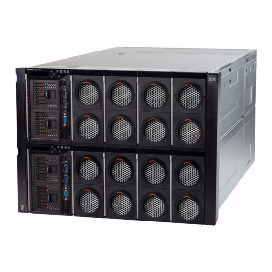
- Page 1 System x3850 X6 and x3950 X6 Types 3837 and 3839 Rack Installation Instructions...
- Page 3 System x3850 X6 and x3950 X6 Types 3837 and 3839 Rack Installation Instructions...
- Page 4 Second Edition (June 2014) © Copyright IBM Corporation 2014. US Government Users Restricted Rights – Use, duplication or disclosure restricted by GSA ADP Schedule Contract with IBM Corp.
-
Page 5: Table Of Contents
Chapter 3. Rack installation ..5 routing the cables . . 15 Identifying the rack space for the server . Removing the server from the rack . 16 Opening the rails . © Copyright IBM Corp. 2014... - Page 6 System x3850 X6 and x3950 X6 Types 3837 and 3839: Rack Installation Instructions...
-
Page 7: Chapter 1. Safety Information
Install your server only in a rack that has perforated front and rear doors or in a ® rack that is equipped with an IBM Rear Door Heat eXchanger. v Do not extend more than one device out of the rack at the same time. - Page 8 ≥ 18 kg (39.7 lb) ≥ 32 kg (70.5 lb) ≥ 55 kg (121.2 lb) Statement 26 CAUTION: Do not place any object on top of rack-mounted devices. System x3850 X6 and x3950 X6 Types 3837 and 3839: Rack Installation Instructions...
-
Page 9: Chapter 2. Rack Kit Parts Inventory
One right cable management bracket (two for 8U system) v One left cable management bracket (two for 8U system) Left cable Right cable management management bracket bracket The optional shipping bracket kit includes the following hardware. You can purchase this kit separately. © Copyright IBM Corp. 2014... - Page 10 (x8) Hex head M5 clip screw (x8) nut (x8) The server might also come with an additional bag with M5 screws, cage nuts, and clip nuts. System x3850 X6 and x3950 X6 Types 3837 and 3839: Rack Installation Instructions...
-
Page 11: Chapter 3. Rack Installation
Chapter 3. Rack installation Use this information to install the IBM System x3850 X6 and x3950 X6 server in a rack cabinet. The server comes with all of the hardware that is necessary for you to install the server in a rack. The instructions in this document apply to both the 4U and the 8U server models. -
Page 12: Rack Mounting
F R O N T Optional shipping screw ® P/N 0000000 Printed in the U.S.A. Screws required to secure rails before installing chassis System x3850 X6 and x3950 X6 Types 3837 and 3839: Rack Installation Instructions... - Page 13 BACK Rack Mounting Template Optional Optional shipping shipping bracket bracket screws screws Note: If the rack rail has round holes, install the M5 clip nuts clip from the installation kit. B AC K Screws required to secure rails before installing chassis Optional Optional shipping...
-
Page 14: Opening The Rails
1. Retract both rails, if they are not already retracted. Grasp the rails on both ends and push the rails in until they are fully retracted. Note: Rail posts and locking hooks are on the ends of each rail. System x3850 X6 and x3950 X6 Types 3837 and 3839: Rack Installation Instructions... -
Page 15: Installing The Rails In The Rack
Installing the rails in the rack This topic provides information on how to install the rails in the rack cabinet. About this task Note: These instructions apply to both the 4U and the 8U server models. Only the 4U is shown in the illustrations. To install the rails in the rack cabinet, compete the following steps: 1. -
Page 16: Installing The Server In The Rack
Note: These instructions apply to both the 4U and the 8U server models. Only the 4U is shown in the illustrations. To install the server in the rack cabinet, complete the following steps: System x3850 X6 and x3950 X6 Types 3837 and 3839: Rack Installation Instructions... - Page 17 55.4 kg (122 lbs) 32 kg (4X) (4X) (70 lbs) 107 kg (230 lbs) (4X) (5X) (5X) 32 kg (4X) (70 lbs) (3X) (3X) 15 kg (33 lbs) 32 kg (70 lbs) 1. Remove the server components (for example, the compute books and power supplies from the front and rear of the server).
- Page 18 5. Slide the server all the way into the rack. 6. To fasten the server into the rack, see “Fastening the server in the rack” on page 13 for more information. System x3850 X6 and x3950 X6 Types 3837 and 3839: Rack Installation Instructions...
-
Page 19: Fastening The Server In The Rack
7. Reinstall all components. See the server documentation for instructions on installing the individual components for the server. After installation of all components, see “Installing the shipping brackets” on page 14 for instructions on how to install the shipping brackets if you plan to transport the rack to another location with the server installed. -
Page 20: Installing The Shipping Brackets
4. Install four M5 hex head screws from the shipping bracket kit in the bottom shipping bracket, two screws on the right side and two screws on the left side. System x3850 X6 and x3950 X6 Types 3837 and 3839: Rack Installation Instructions... -
Page 21: Attaching The Cable Management Brackets And Routing The Cables
Note: Do not tighten the M5 hex head screws complete. 5. After the bottom shipping bracket and screws are installed, tighten all of the screws. Attaching the cable management brackets and routing the cables This topic provides information about how to attach the cable management brackets to the server and route the cables. -
Page 22: Removing The Server From The Rack
See the server documentation for instructions on removing the individual components from the server. 55.4 kg (122 lbs) 32 kg (4X) (4X) (70 lbs) System x3850 X6 and x3950 X6 Types 3837 and 3839: Rack Installation Instructions... - Page 23 107 kg (230 lbs) (4X) (5X) (5X) 32 kg (4X) (70 lbs) (3X) (3X) 15 kg (33 lbs) 32 kg (70 lbs) 7. Slide the server out of the rack; as soon as the handles are beyond the server that is in the rack above the server you are removing, press the blue buttons on the sides of the server to release the lift handles (as shown in the illustration).
- Page 24 8. Remove the screws from the rails (two screws per rail, one in front and one in the rear). 9. Remove the rails from the rack. System x3850 X6 and x3950 X6 Types 3837 and 3839: Rack Installation Instructions...
- Page 26 Part Number: 00FH439 Printed in USA (1P) P/N: 00FH439...
Need help?
Do you have a question about the x3850 X6 and is the answer not in the manual?
Questions and answers