Table of Contents
Advertisement
Advertisement
Table of Contents

Subscribe to Our Youtube Channel
Related Manuals for RADVision Scopia Elite 5100 Series


Summary of Contents for RADVision Scopia Elite 5100 Series
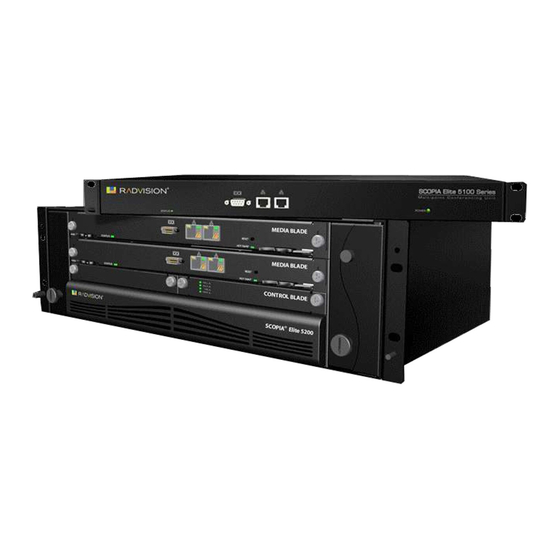
- Page 1 SCOPIA Elite 5100 Series MCU Installation Guide Version 7.7...
- Page 2 If there is any software on removable media described in this publication, it is furnished under a license agreement included with the product as a separate document. If you are unable to locate a copy, please contact RADVISION Ltd and a copy will be provided to you.
-
Page 3: Table Of Contents
Mounting the MCU onto the Rack Using a Shelf ............19 Locating a Shelf in the Rack................ 20 Checking the Accessories Required for Mounting ..........21 RADVISION | Installation Guide for SCOPIA Elite 5100 Series MCU Version 7.7 Table of Contents| i... - Page 4 Configuring the TCP/UDP/TLS Port for SIP on the SCOPIA Elite MCU......50 Configuring Security Access Levels for the SCOPIA Elite MCU ........51 Verifying the MCU Installation ................52 Table of Contents| ii RADVISION | Installation Guide for SCOPIA Elite 5100 Series MCU Version 7.7...
-
Page 5: Main Features Of The Scopia Elite Mcu
• Seamless interoperability The MCU is built on the solid foundation of RADVISION’s H.323 and SIP software, ensuring full compliance and unmatched interoperability with IP, ISDN, and 3G networks. The MCU unites H.323 and SIP devices in the same conference session. - Page 6 Error concealment mechanism: Maintains video quality when 3rd party endpoints are connected to the MCU over lossy networks. – High definition and standard definition participants in the same conference. About the SCOPIA Elite MCU | 2 RADVISION | Installation Guide for SCOPIA Elite 5100 Series MCU Version 7.7...
- Page 7 Snapshot files for Customer Support One-click creation of a file of bundled logs and configuration files which you can send to Customer Support for debugging. About the SCOPIA Elite MCU | 3 RADVISION | Installation Guide for SCOPIA Elite 5100 Series MCU Version 7.7...
- Page 8 Moderators can record meetings using the MCU moderator menu. Note: This feature is only relevant if your SCOPIA Desktop deployment includes the recording option. About the SCOPIA Elite MCU | 4 RADVISION | Installation Guide for SCOPIA Elite 5100 Series MCU Version 7.7...
-
Page 9: Technical Specifications
High Definition Continuous Presence video with a resolution of 1080p at up to 30fps – Video with 720p resolution is sent and received at up to 60fps About the SCOPIA Elite MCU | 5 RADVISION | Installation Guide for SCOPIA Elite 5100 Series MCU Version 7.7... - Page 10 ED (352p) continuous presence (if X4 1/4 - Four times 20 ports 40 ports 60 ports capacity is enabled) the number of calls About the SCOPIA Elite MCU | 6 RADVISION | Installation Guide for SCOPIA Elite 5100 Series MCU Version 7.7...
-
Page 11: Planning Your Mcu Deployment
Planning your Distributed or Centralized Topology for MCU ......page 7 • Ports to Open for the SCOPIA Elite 5100 Series MCU........page 10 Planning your Distributed or Centralized Topology for MCU When your organization has more than one site, like a headquarters and several branches, RADVISION offers a unique method of cutting video bandwidth costs. - Page 12 SCOPIA Solution infrastructure transparently directs you to the correct meeting on the correct MCU. Planning your MCU Deployment | 8 RADVISION | Installation Guide for SCOPIA Elite 5100 Series MCU Version 7.7...
- Page 13 • Avoid cascading as often as possible. For details on configuring cascading conferences, see the Administrator Guide for SCOPIA iVIEW Management Suite. Planning your MCU Deployment | 9 RADVISION | Installation Guide for SCOPIA Elite 5100 Series MCU Version 7.7...
-
Page 14: Ports To Open For The Scopia Elite 5100 Series Mcu
DMZ. When opening ports on the SCOPIA Elite 5100 Series MCU, use the following as a reference: • If you are opening ports that are both in and out of the SCOPIA Elite 5100 Series MCU, see Table 2-1. - Page 15 UDP Port Ranges for (UDP) network RTP/RTCP on the SCOPIA device Elite MCU” on page 43 Planning your MCU Deployment | 11 RADVISION | Installation Guide for SCOPIA Elite 5100 Series MCU Version 7.7...
- Page 16 Cannot configure MCU Mandatory if using (HTTP the MCU Administrator HTTPS over SSL) and Conference Control web user interfaces; used for software upgrade Planning your MCU Deployment | 12 RADVISION | Installation Guide for SCOPIA Elite 5100 Series MCU Version 7.7...
-
Page 17: Preparing The Mcu Setup
Ensure to make necessary changes in case you find that the site does not meet any of the requirements described in that section. RADVISION | Installation Guide for SCOPIA Elite 5100 Series MCU Version 7.7 Preparing the MCU Setup | 13... -
Page 18: Unpacking The Device
Open the shipping box. Step 6 Take the accessories kit out of the shipping box. Step 7 Take the device out of the shipping box. Preparing the MCU Setup | 14 RADVISION | Installation Guide for SCOPIA Elite 5100 Series MCU Version 7.7... -
Page 19: Inspecting For Damage
If you suspect any damage from shipping, contact your local freight carrier for procedures on damage claims. If you observe any physical defects in the items you ordered, contact RADVISION Technical Support for Return Material Authorization (RMA) form. -
Page 20: Setting Up The Mcu
Mounting the MCU onto the Rack Using a Shelf ........... page 19 • Attaching the System Ground ..............page 26 • Connecting Cables to the Device ............page 26 RADVISION | Installation Guide for SCOPIA Elite 5100 Series MCU Version 7.7 Setting up the MCU | 16... -
Page 21: Verifying Rack Suitability
Maintain a minimum clearance of 3 inches (7.62 cm) on the left and right of the device for the cooling air inlet and exhaust vents. Setting up the MCU | 17 RADVISION | Installation Guide for SCOPIA Elite 5100 Series MCU Version 7.7... - Page 22 To mount the MCU between two posts, the width between the inner sides of the two posts must be at least 17.7 inches (45 cm). See Figure 4-4 on page Figure 4-4 Width between inner sides of posts Setting up the MCU | 18 RADVISION | Installation Guide for SCOPIA Elite 5100 Series MCU Version 7.7...
-
Page 23: Complying With Mcu Lifting Guidelines
Removing the Cage Nut Screws .............. page 24 • Mounting the Device-fixing Cage Nuts ............page 24 • Mounting the MCU onto the Shelf............page 24 Setting up the MCU | 19 RADVISION | Installation Guide for SCOPIA Elite 5100 Series MCU Version 7.7... -
Page 24: Locating A Shelf In The Rack
Ensure the shelf is positioned horizontally in the rack. Step 5 Ensure the rack breaks are locked or the rack is stabilized. Setting up the MCU | 20 RADVISION | Installation Guide for SCOPIA Elite 5100 Series MCU Version 7.7... -
Page 25: Checking The Accessories Required For Mounting
Make sure you have a ruler, an Allen wrench (4 mm diameter), and a screwdriver (Nr. 1 tip) ready to hand before you start the setup. Figure 4-6 Accessories required for mounting Setting up the MCU | 21 RADVISION | Installation Guide for SCOPIA Elite 5100 Series MCU Version 7.7... -
Page 26: Attaching Brackets To The Mcu
22. Use the Phillips screws of the accessories kit, as they have the same color as the metal of the bracket. Figure 4-8 Aligning the bracket with the MCU front panel Setting up the MCU | 22 RADVISION | Installation Guide for SCOPIA Elite 5100 Series MCU Version 7.7... -
Page 27: Marking The Location Of The Device-Fixing Cage Nuts
Mark the location of the upper device-fixing cage nut measured at 1.46 inches (3.7 cm) above the shelf. See Figure 4-9 on page Step 3 Repeat this procedure for the other front-facing post. Setting up the MCU | 23 RADVISION | Installation Guide for SCOPIA Elite 5100 Series MCU Version 7.7... -
Page 28: Removing The Cage Nut Screws
Warning The device is heavy and we recommend that you ask someone to help you lift it. Setting up the MCU | 24 RADVISION | Installation Guide for SCOPIA Elite 5100 Series MCU Version 7.7... - Page 29 Insert the four remaining screws you set aside through the bracket holes into the cage nuts in the rack. Using the Allen wrench tighten the screws to secure the device to the front posts. See Figure 4-12 on page Setting up the MCU | 25 RADVISION | Installation Guide for SCOPIA Elite 5100 Series MCU Version 7.7...
-
Page 30: Attaching The System Ground
Procedure Step 1 Connect the power cable: Turn off the power distribution unit (PDU). Setting up the MCU | 26 RADVISION | Installation Guide for SCOPIA Elite 5100 Series MCU Version 7.7... - Page 31 Power on the device using the On/Off switch on the rear side of the device (see Figure 4-13 on page 27). Figure 4-14 Device front panel Turn on the power distribution unit (PDU). Setting up the MCU | 27 RADVISION | Installation Guide for SCOPIA Elite 5100 Series MCU Version 7.7...
- Page 32 MCU Serial connector. This connection is required for local configuration and maintenance. Note: Do not connect a screen or a keyboard to the MCU. Setting up the MCU | 28 RADVISION | Installation Guide for SCOPIA Elite 5100 Series MCU Version 7.7...
-
Page 33: Performing The Mcu Initial Configuration
IP address of the default router the MCU uses to communicate over the network • PC with available serial port and terminal emulator software installed • Serial cable RADVISION | Installation Guide for SCOPIA Elite 5100 Series MCU Version 7.7 Performing the MCU Initial Configuration | 29... - Page 34 Enter the IP address you want to assign to the MCU at the IP address prompt and press Enter (see Figure 5-2 on page 31). Caution Do not use leading zeros in the IP address. Performing the MCU Initial Configuration | 30 RADVISION | Installation Guide for SCOPIA Elite 5100 Series MCU Version 7.7...
- Page 35 Step 19 Allow the unit to complete the reboot process. A new emulator session begins. Step 20 Close the terminal emulator session. Performing the MCU Initial Configuration | 31 RADVISION | Installation Guide for SCOPIA Elite 5100 Series MCU Version 7.7...
-
Page 36: Accessing The Mcu Administrator Interface
‘password’. We highly recommend that you change the default user password for security. You can change a user password at any time. Performing the MCU Initial Configuration | 32 RADVISION | Installation Guide for SCOPIA Elite 5100 Series MCU Version 7.7... -
Page 37: Changing The Mcu Service Prefix
About Supported Languages ..............page 34 • Setting the MCU User Interface Language..........page 34 • Setting a Text Overlay Language ............page 35 Performing the MCU Initial Configuration | 33 RADVISION | Installation Guide for SCOPIA Elite 5100 Series MCU Version 7.7... -
Page 38: About Supported Languages
On a Microsoft Windows operating system, you can set the default language in Control Panel > Regional and Language Options. Performing the MCU Initial Configuration | 34 RADVISION | Installation Guide for SCOPIA Elite 5100 Series MCU Version 7.7... -
Page 39: Setting A Text Overlay Language
Step 3 Select the required language. Figure 5-4 The Video display messages section of the Customize tab Step 4 Select Apply. Performing the MCU Initial Configuration | 35 RADVISION | Installation Guide for SCOPIA Elite 5100 Series MCU Version 7.7... -
Page 40: Configuring Protocols For The Mcu
The Status tab of the Administrator interface opens. Locate the Status Map section. This section is a graphic representation of the MCU chassis Performing the MCU Initial Configuration | 36 RADVISION | Installation Guide for SCOPIA Elite 5100 Series MCU Version 7.7... -
Page 41: Configuring Sip Server Settings
Enter the SIP domain of the MCU in the Default SIP domain field as defined in the SIP server. An example of a SIP domain is company.com. Performing the MCU Initial Configuration | 37 RADVISION | Installation Guide for SCOPIA Elite 5100 Series MCU Version 7.7... - Page 42 To instruct the MCU to register with a SIP registrar and to send service information to the registrar, perform these steps: Select Use registrar. Performing the MCU Initial Configuration | 38 RADVISION | Installation Guide for SCOPIA Elite 5100 Series MCU Version 7.7...
- Page 43 Authentication is performed as defined in RFC 2617. This field is disabled by default. Enter the MCU user name and password. They must match those defined on the SIP server. Performing the MCU Initial Configuration | 39 RADVISION | Installation Guide for SCOPIA Elite 5100 Series MCU Version 7.7...
-
Page 44: Configuring A Dual-Nic Mcu
Performing the MCU Initial Configuration | 40 RADVISION | Installation Guide for SCOPIA Elite 5100 Series MCU Version 7.7... - Page 45 Do not connect the media subnet cable until the MCU has been reset at the end of this procedure. Step 2 Access the MCU in a web browser and login. Step 3 Select the Configuration tab. Performing the MCU Initial Configuration | 41 RADVISION | Installation Guide for SCOPIA Elite 5100 Series MCU Version 7.7...
- Page 46 (Figure 5-12 on page 42), to open the Additional Management Networks section. Enter the IP address of the additional subnet’s router. Performing the MCU Initial Configuration | 42 RADVISION | Installation Guide for SCOPIA Elite 5100 Series MCU Version 7.7...
-
Page 47: Configuring Ports On All Models Of The Scopia Elite Mcu
(for all calls) by a factor of 1.5. Using its full capacity, the SCOPIA Elite 5100 Series MCU uses 180 ports for audio and 540 ports for video, and the SCOPIA Elite 5200 Series MCU uses 360 ports for audio and 1080 ports for video (except for the SCOPIA Elite MCU 5215, which has the same capacity as the SCOPIA Elite 5100 Series MCU). -
Page 48: Configuring The Tcp Port Range For H.245 On The Scopia Elite Mcu
The SCOPIA Elite 5100 Series MCU uses 150 ports for H.245, while the SCOPIA Elite 5200 Series MCU uses 300 ports (except for the SCOPIA Elite MCU 5215, which has the same capacity as the SCOPIA Elite 5100 Series MCU). -
Page 49: Configuring The Http Port On The Scopia Elite Mcu
Navigate to the MCU Advanced Commands section by doing the following: Select the icon. Select Advanced parameters. Locate the CLI section and select More (see Figure 5-13 on page 44). Performing the MCU Initial Configuration | 45 RADVISION | Installation Guide for SCOPIA Elite 5100 Series MCU Version 7.7... - Page 50 For example, if your new HTTP port value is 8080, access the web server by entering the following: http://<URL>:8080 Performing the MCU Initial Configuration | 46 RADVISION | Installation Guide for SCOPIA Elite 5100 Series MCU Version 7.7...
-
Page 51: Configuring The Udp Port For Ras On The Scopia Elite Mcu
Step 3 Enter the port value in the H323 RAS port number field. Step 4 Select Apply. Step 5 Select Close. Performing the MCU Initial Configuration | 47 RADVISION | Installation Guide for SCOPIA Elite 5100 Series MCU Version 7.7... -
Page 52: Configuring The Udp Port For The Gatekeeper On The Scopia Elite Mcu
Select the icon. Select Advanced parameters. Locate the H323 SIG port number in the Name column (see Figure 5-18 on page 49). Performing the MCU Initial Configuration | 48 RADVISION | Installation Guide for SCOPIA Elite 5100 Series MCU Version 7.7... - Page 53 Step 3 Enter the port value in the H323 SIG port number field. Step 4 Select Apply. Step 5 Select Close. Performing the MCU Initial Configuration | 49 RADVISION | Installation Guide for SCOPIA Elite 5100 Series MCU Version 7.7...
-
Page 54: Configuring The Tcp/Udp/Tls Port For Sip On The Scopia Elite Mcu
If your SIP server or Registrar is configured with TLS, you can also configure the port value for TCP/UDP traffic by modifying the Local signaling port field. Step 4 Select Apply. Performing the MCU Initial Configuration | 50 RADVISION | Installation Guide for SCOPIA Elite 5100 Series MCU Version 7.7... -
Page 55: Configuring Security Access Levels For The Scopia Elite Mcu
ICMP (ping) Level Standard Enabled Enabled Enabled Enabled High Disabled Disabled Enabled Enabled Maximum Disabled Disabled Disabled Disabled Step 4 Select Apply. Performing the MCU Initial Configuration | 51 RADVISION | Installation Guide for SCOPIA Elite 5100 Series MCU Version 7.7... -
Page 56: Verifying The Mcu Installation
At a prompt, enter the meeting ID and press #. The MCU creates the conference and you see the Conference window. Exit the conference by disconnecting the call. Performing the MCU Initial Configuration | 52 RADVISION | Installation Guide for SCOPIA Elite 5100 Series MCU Version 7.7... - Page 57 F +44 20 3178 5717 F +852 2801 4071 infoUSA@radvision.com infoUK@radvision.com infoAPAC@radvision.com This document is not part of a contract of license as may be expressly agreed RADVISION is registered trademarks of RADVISION, Ltd. All trademarks recognized. All rights reserved © 2011 RADVISION, Ltd.
Need help?
Do you have a question about the Scopia Elite 5100 Series and is the answer not in the manual?
Questions and answers