NetComm NB6 User Manual
Netcomm gateway series adsl2+ modem routers yml854rev2
Hide thumbs
Also See for NB6:
- User manual (152 pages) ,
- Quick start manual (13 pages) ,
- Specification sheet (2 pages)
Table of Contents
Advertisement
Quick Links
Download this manual
See also:
User Manual
Advertisement
Table of Contents
Troubleshooting

Related Manuals for NetComm NB6


Summary of Contents for NetComm NB6
- Page 1 NB6, NB6W, NB6Plus4, NB6Plus4W, NB6Plus4Wn User Guide YML854Rev2 2 www.netcomm.com.au YML854 Rev2 NB6, NB6W, NB6Plus4, NB6Plus4W, NB6Plus4Wn User Guide www.netcomm.com.au 3 NETCOMM GATEWAY SERIES ADSL2+ Modem Routers USER GUIDE...
-
Page 2: Table Of Contents
Table of Contents Preface..............................4 NB6 Series Package Contents............................5 Before You Use..............................7 Subscription for ADSL Service..............................7 Chapter 1: Overview............................9 NB6 LED Indicators..........................9 NB6 Rear Panel..........................10 NB6W LED Indicators..........................11 NB6W Rear Panel..........................12 NB6Plus4 LED Indicators..........................13 NB6Plus4 Rear Panel..........................14 NB6Plus4W LED Indicators..........................15 NB6Plus4W Rear Panel..........................16... - Page 3 System Requirement..........................20 Do I need a Micro Filter............................21 Choosing a place for the ADSL Router...........................22 Connecting the ADSL Router...........................22 USB Driver Installation..........................23 For Windows ME..............................23 For Windows 2000..........................23 For Windows XP/Vista/7........................24 Uninstalling the USB Driver...........................26 For Windows ME............................26 For Windows 2000..........................26 For Windows XP/Vista/7........................27...
- Page 4 For Mac OSX 10.4...........................29 For Windows XP/Vista/7........................30 Renewing IP Address on Client PC............................33 For Windows 98/ME..........................33 For Windows NT/2000/XP/Vista/7......................33 Chapter 3: Accessing the Internet............................35 PPP over ATM (PPPoA) Mode.............................36 PPP over ATM (PPPoA) IP Extension Mode.............................36 PPP over Ethernet (PPPoE) Mode.............................36 PPP over Ethernet (PPPoE) IP Extension Mode.............................37...
- Page 5 Using Web-Based Manager..........................44 Outline of Web Manager...........................44 To Have the New Settings Take Effect..........................44 Language..........................44 Quick Start............................45 Connect to Internet..........................45 Quick Setup..........................45 Connection Type..........................46 PPP over ATM/ PPP over Ethernet..........................46 IP over ATM..........................49 Bridging...........................51 Status ..............................53 Overview..........................53 ADSL Line..........................53 Internet Connection........................55 Traffic Statistics...........................55 DHCP Table..........................55...
- Page 6 Advanced Setup............................56 Local Network – IP Address..........................56 Local Network – DHCP Server..........................57 Local Network – UPnP..........................58 Local Network – IGMP Snooping..........................59 Internet – Connections........................61 Internet – DNS Server..........................64 Internet – IGMP Proxy..........................64 Internet – ADSL..........................65 IP Routing – Static Route..........................66 IP Routing –...
- Page 7 Firewall – IP Filtering..........................74 Quality of Service..........................77 Quality of Service – Bridge QoS..........................77 Quality of Service – IP QoS..........................78 Port Mapping...........................80 Wireless..........................82 Basic..........................82 Security..........................85 Access Control..........................91 Repeater...........................92 Management........................94 Diagnostics........................94 Management Accounts..........................95 Management Control – From Remote..........................96 Management Control – From Local..........................97 Internet Time..........................97...
- Page 8 UPnP for XP..........................102 Chapter 5: Troubleshooting.........................105 Problems with LAN............................105 Problems with WAN...........................105 Problems with Upgrading...........................106 Chapter 6: Glossary............................108 Appendix A: Client Setup for 802.1x, WPA, and WPA- PSK..............................111 Retrieving Client Certificate...........................111 Enabling 802.1x Authentication and Security..........................113 Enabling WPA Authentication and Security..........................116 Enabling WPA-PSK Authentication and Security..........................117...
- Page 9 WEP encryption...........................125 WPA encryption...........................126 Appendix D: Legal and Regulatory Information..........................127 Customer Information.........................127 Product Warranty..........................127 Limitations of Warranty..........................128...
-
Page 10: Preface
Copyright©2010 NetComm Limited. All rights reserved. The information contained herein is proprietary to NetComm Limited. No part of this document may be translated, transcribed, reproduced, in any form, or by any means without prior written consent of NetComm Limited NOTE: This document is subject to change without notice. -
Page 11: Nb6 Series Package Contents
NB6 Series Package Contents Your Package contains the following items: • One NB6, NB6W, NB6Plus4, NB6Plus4W or NB6Plus4Wn Router • Telephone Cable (RJ-11) • USB Cable (Not available for NB6Plus4 or NB6Plus4Wn) • CAT-5 UTP Straight Ethernet Network Cable (RJ-45) •... -
Page 12: Before You Use
Security is a key issue with Broadband users and NetComm’s Routers do not leave you exposed. Your new Router has a built-in firewall to ensure your defences are rock-solid against hackers, unauthorised entries, probes and even Denial of Service attacks. -
Page 13: Chapter 1: Overview
This chapter provides you with a description for the LEDs and connectors on the front and rear surface of the router. Please take a look at this information, before you use/install this router. NB6 LED Indicators The LED Indicators are located on the front of the unit, their meanings are as follows:... -
Page 14: Nb6 Rear Panel
No USB signal is detected. Flash Green User data is going through USB port Solid Green USB interface is ready to work. NB6 Rear Panel The following figure illustrates the rear panel of your ADSL Router: Connector Description Line RJ-11 connector (Telephone line) - Page 15 Function Color Definition Power is off. Solid Green Power is on and the device operates normally. Power on self-test in progress Power Solid Red The device enters the console mode of the boot loader. Power on self-test failure if the led always stays solid red. Flash Red Firmware upgrades in progress No ADSL signal is detected.
-
Page 16: Nb6W Rear Panel
Flash Green User data is going through WLAN port Solid Green WLAN interface is ready to work. NB6W Rear Panel The following figure illustrates the rear panel of your ADSL Router: Connector Description Wireless antenna Power 12VAC Power connector Power on/off switch Reset Reset to factory defaults Ethernet... -
Page 17: Nb6Plus4 Rear Panel
Function Color Definition Power is off. Solid Green Power is on and the device operates normally. Power on self-test in progress Power Solid Red The device enters the console mode of the boot loader. Power on self-test failure if the led always stays solid red. Flash Red Firmware upgrades in progress No ADSL signal is detected. -
Page 18: Nb6Plus4W Led Indicators
Connector Description Reset Reset to factory defaults Power 12VAC Power connector Power on/off switch Ethernet – 1, 2, 3, 4 Ethernet RJ-45 connector Line RJ-11 connector (Telephone line) NB6Plus4W LED Indicators The LED Indicators are located on the front of the unit, their meanings are as follows: Function Color Definition... -
Page 19: Nb6Plus4W Rear Panel
Power on self-test failure if the led always stays solid red. Flash Red Firmware upgrades in progress No ADSL signal is detected. Slow Flash ADSL line is handshaking in progress Green ADSL Fast Flash ADSL line is training in progress Green Solid Green ADSL line connection is up. -
Page 20: Nb6Plus4Wn Led Indicators
Wireless antenna Reset Reset to factory defaults Power 12VDC Power connector Power on/off switch Ethernet – 1, 2, 3, 4 Ethernet RJ-45 connector USB connector Line RJ-11 connector (Telephone line) NB6Plus4Wn LED Indicators The LED Indicators are located on the front of the unit, their meanings are as follows: Function Color Definition... -
Page 21: Nb6Plus4Wn Rear Panel
Solid Green ADSL line connection is up. No PPPoA or PPPoE connection At least one PPPoA or PPPoE connection is up. The users can access the Solid Green Internet now. No Ethernet signal is detected. Ethernet Flash Green User data is going through Ethernet port 1, 2, 3, 4 Solid Green Ethernet interface is ready to work. -
Page 22: System Requirement
System Requirements Before continuing with the installation of your Router, please confirm that you comply with the minimum system requirements. ® • Pentium MMX 233MHz • A CD-ROM Drive • Ethernet card installed with TCP/IP Protocol (required when connecting to the ETHERNET port of your ADSL Router) •... -
Page 23: Choosing A Place For The Adsl Router
Failure to connect ALL non-ADSL equipment via a microfilter may result in loss of the data link whenever a call is made or answered. In many cases the link will also be lost when a call is received even if it is not answered. Choosing a place for the ADSL Router •... -
Page 24: Usb Driver Installation
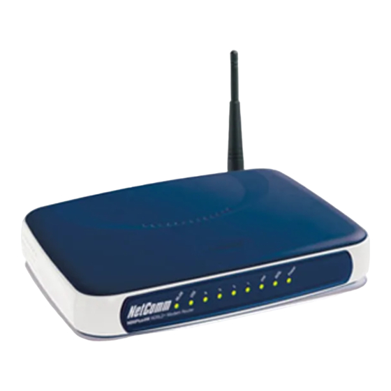
* Model shown is NB6 may vary slightly from image USB Driver Installation (USB is not available for NB6Plus4 or NB6Plus4Wn) If the ADSL router is to be connected to a PC through the USB interface, you will need to install the USB drivers prior to plugging the USB cable to the PC. -
Page 25: For Windows Xp/Vista/7
Right-click on My Computer and press Properties. • On the Hardware tab, click Device Manager. • Confirm that the NetComm NB6 Series ADSL Router USB Remote NDIS Device is on the Network adapters list. For Windows XP/Vista/7 • Run the USB installation program from the CD provided in your router package. - Page 26 To make sure your router is properly installed, please do the following steps. • Right-click on My Computer and press Properties. 2. On the Hardware tab, click Device Manager. 3. Confirm that the NetComm NB6 ADSL Router USB Remote NDIS Device is on the Network adapters list.
-
Page 27: Uninstalling The Usb Driver
To safely unplug the USB cable from the USB port on your PC: Go to the right lower corner for Unplug and Eject Hardware and left click on it. Click the dialog for Stop NetComm ADSL Router USB Remote NDIS Device. The Router is safely removed, click OK to continue. -
Page 28: Setting Up Tcp/Ip
XP) or Programs and Features (Windows Vista/7). • A dialog appears to ask you to choose the program that you want to remove. Please select NetComm NB6 Series ADSL Router USB Driver and click Change/Remove (Windows XP) or Uninstall (Windows Vista/7). •... -
Page 29: For Windows Me
Open the Start menu, point to Settings and click on Control Panel. Double-click the Network icon. The Network window appears. On the Configuration tab, check out the list of installed network components. Option 1: If there is no TCP/IP protocol, click Add. Option 2: If you have TCP/IP protocol, skip to Step 6. -
Page 30: For Windows 2000
Option 2: If you have TCP/IP Protocol installed, skip to Step 7. Highlight TCP/IP Protocol and click OK. Insert the Windows NT CD into your CD-ROM drive and type the location of the CD. Then click Continue. When returning to the Network window. Open the Protocols tab, then select TCP/IP Protocol and click Properties. - Page 31 Double click the Network Connection (Windows XP), View Network status and tasks and then Manage network connections (Windows Vista). or Network and sharing centre (Windows 7). Right click Local Area Connection and then click Properties.
- Page 32 On the General tab, check out the list of installed network components. Option 1: If there is no TCP/IP Protocol, click Install. Option 2: If you have TCP/IP Protocol, skip to Step 7. Highlight Protocol and then click Add. Click Internet Protocol (TCP/IP) and then click OK.
-
Page 33: Renewing Ip Address On Client Pc
When it returns to the General Tab on the Local Area Connection Properties window, highlight Internet Protocol (TCP/IP) and then click Properties. Under the General tab, select Obtain an IP address automatically, and Obtain DNS server address automatically. Then click Ok. Renewing IP Address on Client PC... -
Page 34: For Windows 98/Me
After the ADSL Router gets on line, there is a chance that your PC does not renew its IP address and thus causes the PC not able to access the Internet. To solve this problem, please follow the procedures below to renew PC’s IP address. For Windows 98/ME Select Run from the Start menu. -
Page 35: Ppp Over Atm (Pppoa) Mode
• Numbered IP over ATM (IPoA) • Numbered IP over ATM (IPoA) + NAT • Unnumbered IP over ATM (IPoA) • Unnumbered IP over ATM (IPoA) + NAT • Bridge Mode • MER (Bridge Mode + NAT) To ensure your PC accesses the Internet successfully, please check the following first. •... -
Page 36: Ppp Over Atm (Pppoa) Ip Extension Mode
Check DHCP Server on box. And key in the start and end IP address, e.g.: Start IP Address: 192.168.1.2 End IP Address: 192.168.1.254 Then enter the leased time (the default is 1 day), and click Next. Check the network information on This Internet Connection -- Summary page. Make sure the settings match the information provided by your ISP. -
Page 37: Ppp Over Ethernet (Pppoe) Ip Extension
• VPI – 8 • VCI – 35 Click the Next button. On the Configure Internet Connection – Connection Type page, select PPP over Ethernet (PPPoE) then click the Next button. On the WAN IP Settings page, select “Obtain an IP address automatically” and check Enable NAT box. -
Page 38: Numbered Ip Over Atm
On the PPP Username and Password page, enter the PPP username and password offered by your ISP. Select “Always on” and then click “Next”. Check the network information on This Internet Connection -- Summary page. Make sure the settings match the settings provided by the ISP. Click Apply. Press Finish. -
Page 39: Numbered Ip Over Atm (Ipoa)+Nat
Check Configure the second IP Address and Subnet Mask for LAN Interface and enter the information needed. Secondary IP Address: 10.11.80.81 Subnet mask: 255.255.255.248 Click Next. Check the network information on the Summary page. Make sure the settings match the settings provided by your ISP. -
Page 40: Unnumbered Ip Over Atm
WAN IP Address: 10.11.80.81 WAN Subnet Mask: 255.255.255.248 Primary DNS server: 168.95.1.1 Secondary DNS server: 168.95.192.1 Check the Enable NAT box. And click “Next”. On the Configure LAN side Settings page, key in the information for your LAN, e.g., Primary IP Address: 192.168.1.1 Subnet mask: 255.255.255.0 Start IP Address: 192.168.1.2 End IP Address: 192.168.1.254... -
Page 41: Unnumbered Ip Over Atm (Ipoa)+Nat
On the Configure LAN side Settings page, key in the information for your LAN, e.g., Primary IP Address: 192.168.1.1 Subnet mask: 255.255.255.0 Start IP Address: 192.168.1.2 End IP Address: 192.168.1.254 Check Configure the second IP Address and Subnet Mask for LAN Interface and enter the information needed, e.g., Secondary IP Address: 10.11.80.81 Subnet mask: 255.255.255.248... -
Page 42: Bridge Mode
On the Configure Internet Connection – Connection Type page, select IP over ATM (IPoA) then click “Next”. On the WAN IP Settings page, select “None” for WAN IP address settings. Then, select Use the following DNS Server Address and key in the information that your ISP offered, e.g.: Primary DNS server: 168.95.1.1 Secondary DNS server: 168.95.192.1 Check the Enable NAT box. -
Page 43: Mer
On the Configure Internet Connection – Connection Type page, select Bridging then click the Next button. On the WAN IP Settings page, select “None” for WAN IP address settings. On the Configure LAN side Settings page, enter the IP address and subnet mask for your LAN, e.g.: Primary IP address: 192.168.1.1 Subnet Mask: 255.255.255.0... -
Page 44: Chapter 4: Web Configuration
On the Configure LAN side Settings page, key in the IP address and subnet mask for your LAN. Check DHCP Server On box, and enter the start and end points, e.g.: Primary IP address: 192.168.1.1 Subnet Mask: 255.255.255.0 Start IP Address: 192.168.1.2 End IP Address: 192.168.1.254 Then key in the leased time that you want. -
Page 45: To Have The New Settings Take Effect
The main screen will be shown as below. Title: The title of this management interface. Main Menu: Including Quick Start, Status, Advanced, Wireless (wireless models only), and Management. Main Window: The current workspace of the web manager, containing configuration or status information. -
Page 46: Connection Type
The quick setup wizard will guide you to configure the ADSL router through some specific steps. Refer to the following pages for detailed information. Auto Scan Internet Connection (PVC): If your ADSL router does not have PVC configuration inside, you can check this box. Otherwise, please uncheck this box. - Page 47 Choose PPPoA or PPPoE and click Next. On this screen, you have to make the settings for WAN IP. To get the IP address automatically, click the Obtain an IP address automatically button. Or click Use the following IP address button and enter the IP address for WAN interface.
- Page 48 On the Configure LAN side Settings page, you have to fill in the data requested. Primary IP Address & Subnet Mask: Key in the information that offered by your ISP for the LAN connection. Configure the secondary IP Address and Subnet Mask: Check this box to set up a secondary IP Address to connect to your router if they are not included in the range that DHCP server accepts.
-
Page 49: Ip Over Atm
You can check the contents on the Summary page. If you find anything incorrect, click Back to modify the settings. If everything is OK, click Finish to accept these settings. Now, the system will reboot to activate the new settings that you have set in this section. Please wait for 2 minutes before restarting the router. - Page 50 Select this item to set the DNS server addresses manually, type the information provided by your ISP in the following Primary DNS and Secondary DNS server entries, e.g. 168.95.1.1 and 168.95.192.1. Click Enable NAT if you want. After setting up the WAN IP and DNS server information, click Next to open the following page. On the Configure LAN side Settings page, you have to fill in the data requested.
-
Page 51: Bridging
Lease Time: Key in the duration for the time. The default is 1day. DHCP Server Off: Check this item if DHCP service is not needed on the LAN. Key in all the necessary settings. Click “Next” for the coming page. You can check the settings on the Summary page. - Page 52 Click this button to allow the system to get an IP address automatically. WAN IP Address, WAN Subnet Mask, and Default Gateway: When choosing Use the following IP address, you have to key in the IP address, the subnet mask, and the default gateway provided by your ISP for the WAN interface.
-
Page 53: Status
You can check the settings on the Summary page now. If you find anything incorrect, click Back to modify the settings. If everything is OK, click Finish to accept these settings. And the following page will appear. Now, the system will reboot to activate the new settings that you have done in this section. Please wait for 2 minutes before restarting the router. - Page 54 This page shows all information for ADSL. For knowing the quality of the ADSL connection, please click ADSL BER Test button to have advanced information. Click More Information hyperlink to see more detailed information about ADSL Line Status. ADSL BER Test This test determines the quality of the ADSL connection.
-
Page 55: Internet Connection
Click Close to close this window. Internet Connection This page displays the connection information for your router, such as the PVC name, VPI/VCI value, service category, protocol, invoking NAT and QoS or not, IP address, linking status, and so on. Traffic Statistics This table shows the records of data going through the LAN and WAN interface. -
Page 56: Routing Table
Routing Table This table shows the routing rules that your router uses. ARP Table This table shows the IP address record for IP-to-Physical translation in your router. Advanced Setup Note: These pages may differ in appearance between each model. The information is the same, however the order they appear can be different to what is shown below. -
Page 57: Local Network - Dhcp Server
Key in the subnet mask that you received from your ISP for the LAN connection. Host Name: List the host name of this device. Domain Name: List the name of the domain. Configure the secondary IP Address and Subnet Mask: Check this box to enter another set of IP Address and Subnet Mask to connect to your router if they are not included in the range that DHCP server accepts. - Page 58 You have to key in Start IP Address, End IP Address, and Lease Time. The default lease time is 1day. Relay On: Click this button to have a relay setting. And type the Server IP in the IP field. When the DHCP server is served by another device rather than the router itself, you can relay to that specific server and enter the IP address of it, as 10.11.95.2 in our example.
-
Page 59: Local Network - Upnp
You may click Add button to add another set or click “Close” to exit. Local Network – UPnP The UPnP is only available for Windows XP/Vista/7. If you are not a Windows XP/Vista/7 user, you may ignore this page. Enabling the UPnP IGD and NAT traversal function allows the users to perform more applications behind NAT without additional configuration settings or ALG support on your ADSL Router. -
Page 60: Internet - Connections
When IGMP snooping is invoked, it makes the system aware to establish the best path for multicast service to save LAN bandwidth. Refer the figure below, just as desired, only host A and D will actually receive multicast traffic when IGMP snooping is enabled. While IGMP snooping is enabled, the IGMP packets will be monitored, the membership information will be recorded and processed, and the multicast traffic will only be forwarded to those LAN interfaces, such as Ethernet, Wireless, and USB, which are bonded to the subscribed multicast groups. - Page 61 If you click the Connect hyperlink under the PVC Name item, the system will connect to WAN automatically. If the WAN connection is OK, you can check the detailed information directly. You can add new PVC(s) by clicking the Add button, edit the settings for the present PVC by clicking in the Edit column, or delete the existing PVC by pressing icon.
- Page 62 If you choose PPPoE (or Bridging), you will see the option for 802.1Q VLAN Tagging. 802.1Q VLAN Tagging: NOTE: This option is not available on the NB6 802.1Q-compliant switch ports can be configured to transmit tagged or untagged frames. A tag field containing VLAN (and/or 802.1p priority) information can be inserted into an Ethernet frame.
- Page 63 Notice that 802.1Q VLAN Tagging function can only be invoked under PPPoE and Bridging Mode; the system will not provide this option while setting PPPoA or IPoA mode. Click Next to continue. The WAN IP settings page will differ slightly according to the protocol that you choose. This graphic is the one that you will see if you choose the PPPoE mode in the previous step.
-
Page 64: Internet - Dns Server
If you choose Bridging from the Connection Type web page, you will get a web page as below. Please refer to Quick Setup for more information. Internet – DNS Server If Enable Automatic Assigned DNS checkbox is selected, this router will accept the first received DNS assignment from one of the PPPoA, PPPoE or MER/DHCP enabled PVC(s) during the connection establishment. -
Page 65: Internet - Adsl
The hosts interact with the system through the exchange of IGMP messages. When you want to configure IGMP proxy, the system will interact with other routers through the exchange of IGMP messages. However, when acting as the proxy, the system performs the host portion of the IGMP task as follows: •... -
Page 66: Ip Routing - Static Route
reconfiguration, the total data rate and the data rate on each latency path is unchanged. Check this box to enable the function. If not, uncheck this box to close the function. Seamless Rate Adaptation: It enables the ADSL2/ ADSL2+ Router to change the data rate of the connection while in operation without any service interruption or bit errors. - Page 67 Click this button to forward packets to the specific gateway. Key in the gateway IP address that you want to use. WAN Interface: Click this button to forward packets to a specific WAN interface. Choose one from the drop-down menu. E.g., type 192.168.1.1 in the field of the gateway IP address and leave the destination network blank.
-
Page 68: Ip Routing - Dynamic
Gateway: 192.168.1.254 (Router B) IP Routing – Dynamic Routing (NB6Plus4W/NB6Plus4Wn only) Routing Information Protocol (RIP) is utilized by means of exchanging routing information between routers. It helps the routers to determine optimal routes. This page allows you to enable/disable this function. - Page 69 IP Address seen by Internet Users Once configured, anyone on the Internet can connect to your Virtual Servers. Please note that, in the above picture, both Internet users are connecting to the same IP address, but using different protocols, such as Http://203.70.212.52 and Ftp://203.70.212.52. To Internet users, all virtual servers on your LAN have the same IP Address.
- Page 70 For example, if you choose Audio/Video in the first field, the corresponding contents of the second field would be like the drop-down list shown as the following figure. User defined: Type a new service name for building a customized service for specific purpose. There are three lines that you can enter settings into on this page.
-
Page 71: Virtual Server - Port Triggering
If you do not want the server that you created, check the Delete box of that application and click the Delete button to discard it. Or if you want to add another one, click Add to add a new one. Virtual Server –... -
Page 72: Virtual Server - Dmz Host
Virtual Server – DMZ Host In computer networks, a DMZ (demilitarized zone) is a computer host or small network inserted as a “neutral zone” between a company’s private network and the outside public network. It prevents outside users from getting direct access to a server that has company data. A DMZ is an optional and more secure approach to a firewall and effectively acts as a proxy server as well. -
Page 73: Virtual Server - Static Dns
Select the interface from the drop-down list that you want to use for connecting the Internet. User Name / Password: Enter the user name and password that you registered with the provider. Host Name. Domain Name: Key in the domain name or host name that you registered. You can use letters and dash for naming, yet other characters are not allowed to use for preventing from making troubles. -
Page 74: Firewall
The VPN ALG allows two or more simultaneous VPN connections through this router Enable SIP ALG The SIP ALG allow two or more simultaneous VoIP phone calls made by VoIP clients through this router Firewall The firewall is a kind of software that interrupts the data between the Internet and your computer. It is the TCP/IP equivalent of a security gate at the entrance to your company. - Page 75 To initiate the IP Filtering, please select the Enabled radio button and click Apply. Select the direction to filter packets: Inbound means the data is transferred from outside onto your computer. Outbound means the data is transferred from your computer onto outside through Internet. Please choose Outbound traffic or Inbound traffic as the direction for filtering packets.
- Page 76 Source/Destination IP address: To specify IP address to allow or deny data transmission, please pull down the drop-down menu to choose a proper one. The setting All means that all the IP addressed in the network are allowed or denied to pass through in Internet.
-
Page 77: Quality Of Service
To add a new Inbound IP Filtering, click Inbound traffic in the item of Select the direction to filter packets on the IP Filtering page. Use the same way to add a new one as stated above. Quality of Service QoS (Quality of Service) is an industry-wide initiative to provide preferential treatment to certain subsets of data, enabling that data to traverse the Internet or intranet with higher quality transmission service. -
Page 78: Quality Of Service - Ip Qos
IP Precedence: The number you choose here decides the type of the IP address processed. No change is the default setting. IP type of Service: The system provides some types of service for you to choose. The meaning of each type is the same as the denotation. - Page 79 Traffic Class Name: Type a name as the traffic class for identification. LAN Ports which traffic come from: The IP QoS rules will be applied on the LAN ports you checked here. The default setting includes all interfaces. Protocol: Choose a proper interface for this function. If you don’t know how to select, simply use the default one, TCP/UDP.
-
Page 80: Port Mapping
According to the example, we set four rules for IP QoS. In traffic A, we set 1-1024 as the destination port, and the traffic priority is low; in traffic B, the source port is from 201 to 8000, and the priority is medium;... - Page 81 Virtual LAN Function on Ethernet: If you click Disabled, the LAN ports for Ethernet ports will only be shown as an Ethernet interface. After applying Enabled, the LAN ports will be viewed as four separated ports shown on the status chart as below.
-
Page 82: Wireless
Now we are going to map USB, Wireless, and the first Ethernet port together with the bridge mode PVC. Click br_0_35 and press Add button, then use the same way to add USB, Wireless, and Ethernet1 to grouped interfaces. The four items are moved to the right box now. When the setting is done, click Apply. -
Page 83: Basic
This page allows you to configure the router as an Access Point. You may setup the settings for security, access control, and repeater features for this device. Basic– NB6W and NB6Plus4W only To set the basic configuration for the wireless features, please open Basic page from the Wireless menu. - Page 84 It decides the mode of data transmission. Choose the one that you want to use from the drop-down menu. There are 802.11b only, 802.11g only and Mixed Mode provided here. Channel: The frequency in which the radio links are about to be established. Select one channel that you want from the drop down list.
- Page 85 To set the basic configuration for the wireless features, please open the Basic page from the Wireless menu. Wireless Interface The number of the wireless interface. The NB6Plus4W supports up to four interfaces. Network Name (SSID) The system will detect the SSID of your router and it will be displayed in this field for your reference. The SSID is the identification characters of a router.
- Page 86 Channel: The frequency in which the radio links are about to be established. Select one channel that you want from the drop down list. As an administrator of the network, one must search which channels are available and then assign one available channel as the communication channel.
-
Page 87: Security
When it is enabled, the data transmission will be faster for this router. Check Enabled to invoke this function for speeding up the transmission, or check Disabled to close this function Afterburner: When it is enabled, the maximum data transmission will be faster for this router. Check Enabled to invoke this function for speeding up the transmission, or check Disabled to close this function. - Page 88 as 64 bit Wired Equivalent Privacy or WEP for short. The default 64 bit Hexadecimal WEP key is: a1b2c3d4e5 Select the WEP mode for the security function; there are two options, 64-bit and 128-bit. Before being transmitted, the data will be encrypted using the encryption key. For example, if you set 64-bit in this field, then the receiving station must be set to use 64 Bit Encryption, and have the same Key value at the same time;...
- Page 89 Wireless Security: Choose 802.1x as the authentication protocol, your data transmission between the router and the clients will be protected with the settings that you set in this web page. RADIUS Server IP Address: RADIUS Server is a protocol for carrying authentication, authorization, and configuration information between a Network Access Server which desires to authenticate its links and a shared Authentication Server.
- Page 90 The WPA (WiFi-Protected Access) authentication is suitable for enterprises. It must be used in conjunction with an authentication server such as RADIUS to provide centralized access control and management. It can provide stronger encryption and authentication solution than none WPA modes. Data Encryption: Select the data encryption method for the WPA mode.
- Page 91 WPA-PSK (WPA-Pre-Shared Key) is useful for small places without authentication servers such as the network at home. It allows the use of manually-entered keys or passwords and is designed to be easily set up for home users. Data Encryption: Select the encryption type for the WPA mode. There are three types that you can choose, TKIP, AES, TKIP+AES.
-
Page 92: Access Control
The WPA2 is suitable for enterprises. It must be used in conjunction with an authentication server such as RADIUS to provide centralized access control and management. It can provide stronger encryption and authentication solution than other WPA mode. Data Encryption: Select the encryption type for the WPA2 mode. - Page 93 The web page allows you to enable the wireless MAC control configuration. Access Control: Click Off to disable this function. Click On in Allow mode to allow the devices using matched MAC address to link to the AP. And click On in Deny mode to disturb the listed wireless MAC address to access the AP.
-
Page 94: Repeater
The result of the added MAC address will be shown on the table. If you want to delete the added MAC address, simply click the delete button , a dialog box will be prompted to confirm the deleting. Click Yes, and then the selected one will be erased. Repeater A repeater is an electronic device that receives a weak or low-level signal and retransmits it at a higher level or higher power, so that the signal can cover longer distances without degradation. -
Page 95: Management
AP Mode: Choose an AP mode that you would like to use. Search Other Repeaters: You can configure other routers as your repeater by setting up repeater feature mutually. Click the Scan Now button to search other repeater in the wireless network automatically. The result will be shown on the chart. -
Page 96: Management Accounts
Press Run Diagnostic Tests on the Diagnostic Tests page. The Result would be shown on the same page. For the item which passes through the diagnostics, a “PASS” will be displayed on the right side of that item. If not, a “FAIL” will be presented there. If there is no device using that port, a “DOWN”... -
Page 97: Management Control - From Remote
There are various interfaces for the remote access. Please choose from them if you want to enable the remote access control. Note: NB6 supports Web Browser, Telnet, TFTP and Ping only Select the Internet Connect: Select one connection item from the drop-down list to enable the function. -
Page 98: Management Control - From Local
Click Apply to save your setting. Management Control – From Local You can allow local access to your router via the checked interfaces. Note: NB6 supports Web Browser, Telnet, TFTP and Ping only Authorized Host IP Address List: Refer to Remote Management Control. -
Page 99: System Log
The default setting is Manual. Select this one, and set the start time by typing the date and the time manually to help the router perform tasks. If you select Time Server, the system will set time via time server automatically. Primary Time Server/ Secondary Time Server: You may select the preferred time server from the drop-down list. - Page 100 Log Level: This function enables you to decide how detailed the messages will be stored. Set a proper level according to your needs. The default Log Level is Debugging. The Debugging Level logs all messages to the file, while the Emergency Level logs fatal messages only. The lower the item is, the more detailed information it provides;...
- Page 101 System Log Configuration Choose Enabled Log. Select Debugging as the Log Level, and Error as the Display Level. (Or select other level according to your needs.) Set the Mode as Both, key in the Server IP Address as 10.11.95.2, and leave the Server UDP Port as the default value 514.
-
Page 102: Backup Configuration
For example, message 1 shows alert level information which is a kernel process containing detailed intrusion information; message 2 displays notice level information which is an IGMP process exhibiting that the IGMP function had been started. Viewing System Log – Local Side (ADSL Router) For viewing the system log on local side, click the View System Log button on the webpage for system log configuration. -
Page 103: Update Firmware
Click Backup button and the warning window will be prompted. Click OK to continue the backup procedure. The system will ask your command about the next procedure. Click Save to backup. You may change the file name and choose a place to save the backup file. And when you want to restore the settings in the future, simply open Backup Config web page and use Browse button to locate the file. -
Page 104: Reset Router
When it is finished, the system will tell you the update is successfully. Note: Latest firmware update can be found at www.netcomm.com.au. Note: Router must not turn off during firmware updates. Reset Router To make the settings that you set for this router take effect, please open the Reset Router web page and click the Reboot button to invoke all settings. -
Page 105: Chapter 5: Troubleshooting
Select Networking Services and click Details. Click the UPNP User Interface check box. Click OK. The system will install UPnP components automatically. After finishing the installation, go to My Network Places. You will find an icon (e.g., Wireless ADSL2+ Router) for UPnP function. Double click on the icon, and the ADSL router will open another web page via the port for UPnP function. -
Page 106: Problems With Wan
The chances are that the interface used as DHCP server is modified and the client PCs do not renew IP addresses. If your DHCP server is enabled on Private IP Address previously and you modify the interface to Public IP Address, the client PCs should renew IP addresses. The PC on the LAN cannot access the Web page of the ADSL Router. -
Page 107: Chapter 6: Glossary
Action: Setup you PC with a static IP address, such as 192.168.1.2, and then access the router’s web page by entering http://192.168.1.1. Then update the firmware again. • Error Message: Image uploading failed. The selected file contains an illegal image. Possible cause: The firmware file format is invalid. - Page 108 When operates as a DHCP server, the ADSL Router assign IP addresses to the client PCs on the LAN. The client PCs “leases” these Private IP addresses for a user-defined amount of time. After the lease time expires, the private IP address is made available for assigning to other network devices. The DHCP IP address can be a single, fixed public IP address, an ISP assigned public IP address, or a private IP address.
-
Page 109: Appendix A: Client Setup For 802.1X, Wpa, And Wpa-Psk
A PVC is a logical point-to-point circuit between customer sites. PVCs are low-delay circuits because routing decisions do not need to be made along the way. Permanent means that the circuit is pre- programmed by the carrier as a path through the network. It does not need to be set up or turned down for each session. - Page 110 For example, if the Microsoft Certificate Service server uses the IP address 192.168.0.2, then we have to key in http://192.168.0.2/certsrv on the URL box. You will be asked to log in, use your domain credentials. (e.g., ABC) Make sure that Request a certificate is selected, and click “Next”. Select User Certificate, then “Next”.
-
Page 111: Enabling 802.1X Authentication And Security
Click Submit. You may retrieve your certificate by clicking Install this certificate. You’ll receive a confirmation message about accepting the certificate, click Yes Enabling 802.1x Authentication and Security... - Page 112 Click Run from the Start menu. Type services.msc and click OK. Scroll to the bottom of the list. Double click on the Wireless Zero Configuration service and verify that it is set to Automatic and that it is started. Click OK to continue. Click the Start button, select Control Panel, then Network Connections.
- Page 113 In the Trusted Root Certification Authorities field, check the check box beside the name of the certificate authority from which the server certificate was downloaded. (e.g., NetComm.savd.tw) Note that if you leave all check boxes unchecked, you will be prompted to accept a connection to the...
-
Page 114: Enabling Wpa Authentication And Security
Click OK twice to close the dialogs until return to Wireless Networks tab of wireless properties. Now we can see the wireless network which we have just set up being displayed on the Preferred networks. Click OK to save your settings. The configuration is complete. Enabling WPA Authentication and Security The first four steps are the same as the setting for 802.1x authentication, please refer to the previous part. - Page 115 In the Trusted Root Certification Authorities field, check the check box beside the name of the certificate authority from which the server certificate was downloaded. (e.g., NetComm.savd.tw) Note that if you leave all check boxes unchecked, you will be prompted to accept a connection to the...
-
Page 116: Enabling Wpa-Psk Authentication And Security
Click OK three times to close the dialogs and save all the settings until return to Network Connections. Now the configuration for WPA authentication is completed. And you may start to use the wireless device. Enabling WPA-PSK Authentication and Security Click the Start button, select Control Panel, then Network Connections. -
Page 117: Appendix B: Establishing Your Wireless Connection
The Network with WPA-PSK authentication has been set up, and is displayed in the preferred networks field. Now the configuration for WPA-PSK authentication is completed. Appendix B: Establishing your wireless connection (For NB6W/Plus4W/ Plus4Wn only) The following examples use the default wireless configuration. Windows XP service pack 2 Follow these steps: Open Network Connections (Start >... -
Page 118: Mac Osx 10.4
Right-click on your Wireless Network Connection and select View Available Wireless Networks: Select the wireless network you want to connect to and click Connect: Enter the network key (default network key is “A1B2C3D4E5”) and click Connect: The connection will show Connected. Mac OSX 10.4 Follow these steps: Click on the Airport icon on the top right menu. -
Page 119: Windows Vista
Click on the network name that you want to connect. The default wireless network name is “wireless”. On the new window, tick on Show Password and type in the network key in the Password field. The default network key is “A1B2C3D4E5”. After that, click on OK. To check the connection, click on the Airport icon and there should be a tick on the wireless name. - Page 120 Click on “Connect to a network”. Choose “Connect to the Internet” and click on “Next”. Choose “Wireless”.
- Page 121 Click on the wireless network name. In this example, the wireless network name is “wireless” and click “Connect”. The default wireless network name is “wireless”. If you have not change the wireless network name, please click on “wireless”. Tick on “Display Characters” and type in the network key. The default network key is “A1B2C3D4E5”...
-
Page 122: Troubleshooting
Tick on both “Save this network” and “Start this connection automatically” and click on “Next”. Now the connection is ready. Notes: For other operating system such as Windows 98SE, Windows ME and Windows 2000 or the wireless adaptor utility to configure your wireless connection, please consult the wireless adaptor documentation respectively. -
Page 123: Appendix C: How To Change Wireless Security On Your Nb6W/Nb6Plus4W
Enable Wireless Zero Configuration by following these steps: Click on the Start Menu. Click on Run, type in “services.msc” (without the quotes). Press OK. Scroll down to the bottom of the list, locate the service named Wireless Zero Configuration and double-click on it. Change the Start-up type to Automatic and check the “Service status”. -
Page 124: Wpa Encryption
Click on “Wireless” menu at the top Click on “Security” on the left Change “Key 1” from “a1b2c3d4e5” to the new encryption. Please note that WEP Encryption key can only use numbers from 0 to 9 and letters from A to F. 64 bit Cipher needs 10 digits Encryption key and 128 bit Cipher needs 26 digits Encryption key. - Page 125 At the log in screen, enter the Username and password. The default Username is “admin” and the default Password is “admin”. Then click on “Login”. Click on “Wireless” menu at the top Click on “Security” on the left Change “Wireless Security” to “WPA-PSK” on the top menu Enter the key in “Pre-Shared Key”...
-
Page 126: Appendix D: Legal And Regulatory Information
NetComm. Failure to do so may cause damage to this product, fire or result in personal injury. -
Page 127: Limitations Of Warranty
To the extent permitted by the Relevant Acts, in relation to your product and any other materials provided with the product (“the Goods”) the liability of NetComm under the Relevant Acts is limited at the option of NetComm to: •... - Page 128 P: 02 9424 2070 F: 02 9424 2010 E: int.sales@netcomm.com.au W: www.netcommlimited.com. Product Warranty NetComm products have a standard 12 months warranty from date of purchase. However some products have an extended warranty option, via registering your product online at the NetComm website www.netcommlimited.com.
Need help?
Do you have a question about the NB6 and is the answer not in the manual?
Questions and answers