IDTECK STAR 505R User Manual
Access controller
Hide thumbs
Also See for STAR 505R:
- User manual (54 pages) ,
- Quick installation manual (21 pages) ,
- Quick install manual (4 pages)

Related Manuals for IDTECK STAR 505R


Summary of Contents for IDTECK STAR 505R
- Page 1 ID TECK STAR 505R ACCESS CONTROLLER USER’S MANUAL STAR 505R Access Controller ID TECK Co. Ltd. 505R-20011128...
-
Page 2: Table Of Contents
ID TECK STAR 505R ACCESS CONTROLLER Table of Contents 1. Important Safety Instructions 2. General 3. Features 4. Specification 5. Front Panel Description 6. Identifying Supplied Parts 7. Installation of the Product 8. Color Coded & Wiring Table 9. System Wiring for Typical Application 10. -
Page 3: Important Safety Instructions
ACCESS CONTROLLER 1. Important Safety Instructions When using your STAR 505R, basic safety precautions should always be followed to reduce the risk of fire, electrical shock, and injury to persons. In addition, the following safety guides should also be followed: 1. -
Page 4: General
ID TECK STAR 505R ACCESS CONTROLLER 2. General The STAR505R is a highly advanced, intelligent single door controller with a dual 8bit microprocessor to meet the market requirement for a robust integrated solution for access control and time & attendance. -
Page 5: Specification
ID TECK STAR 505R ACCESS CONTROLLER 4. Specification : Dual 8bit Microprocessor Memory : Program memory(64KB ROM) Data memory(128KB RAM : battery backup) Power : DC 12V/ 150mA max. Proximity reader : Built-in Proximity reader with up to 4” of read range with IDC... -
Page 6: Front Panel Description
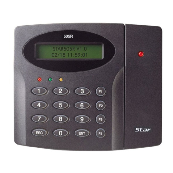
ID TECK STAR 505R ACCESS CONTROLLER 5. Front Panel Description Card Read Status LED System Operation Status LED 16 Numeric Keypad Function Key 6. Identifying Supplied Parts Please unpack and check the contents of the box. Main Unit Wall Mount... -
Page 7: Installation Of The Product
7-2. Using 2 screws, install wall mount to the wall. * CAUTIONS * Before mounting the STAR 505R unit to the Wall Mount bracket, operational test of the unit should be completed, as the locking pins will lock the unit to the Wall Mount. Removing the unit from the Wall Mount bracket after they have been installed together may cause damages to the bracket and render its effectiveness. -
Page 8: Color Coded & Wiring Table
ID TECK STAR 505R ACCESS CONTROLLER 8. Color Coded & Wiring Table I/O PORT NAME SIGNAL NAME WIRE COLOR POWER Main Power (+12V) +12V Red wire Power Ground Black wire OUTPUT Door RELAY(COM) COM(1) Gray wire with Red stripe Door RELAY(NC) -
Page 9: System Wiring For Typical Application
ID TECK STAR 505R ACCESS CONTROLLER 9. System Wiring for Typical Application EXIT EXIT BUTTON CONTACT DOOR CONTACT AUX IN#1 +12V DOOR ALARM RELAY RELAY SENSOR DOOR ALARM RELAY RELAY +12V DC 12V Power Supply DOOR LOCK SIREN 9-1. Power Connection... - Page 10 ID TECK STAR 505R ACCESS CONTROLLER 9-3. Alarm Device Connection - Connect Alarm RELAY(COM), White wire to DC +12V (be sure that the existing power supply has enough capacity to support this accessory or upgrade to a sufficient one.) - Connect (+) wire of Alarm Device to Alarm RELAY(NO), Purple wire of main unit.
-
Page 11: Wiring For Network
11-1. Standalone Operation. The STAR 505R is capable of having two readers (entry and exit). The unit receives card data signals from the RF readers and determines whether or not to unlock the door. When an input signal is sent, for example from an activated sensor or if the exit button pressed, the controller generates and logs an appropriate response. - Page 12 ID TECK STAR 505R ACCESS CONTROLLER 11-5. Anti-Pass-Back Using an additional RF reader for exiting, the Anti-Pass-Back mode can be utilized. Anti-pass-back prevents a registered user from exiting if the user did not properly register when entering. Likewise if the user has exited without verification by the unit, the user will not be allowed entry on their next attempt.
-
Page 13: Operation
ID TECK STAR 505R ACCESS CONTROLLER 12. Operation 12-1. Normal Operation Mode (Safe Mode) When the Main Unit operates in standby mode (waiting for RF card), the red LED is lit. 12-2. Open the Door When a registered card (or PIN) is read, the Door will open for 3 seconds.(default) Registered Card(or PIN) 12-3. -
Page 14: Basic Settings
If you turn on the system GENERAL BOOT power after connecting 3 wires (pink, cyan and black INITIAL BEEP (GND)), you can enter into LCD display : STAR 505R [F4] system initialize mode. MM/DD hh/mm/ss "Initialize END" LCD displays model name, "Turn OFF Power..."... - Page 15 ( pink, cyan, black ) . System initialization completion 13.3 Enter into setup menu INITIAL DISPLAY (MODEL NAME, CURRENT TIME) To set or to change the STAR 505R access controller's operation, enter the eight-digit ID INPUT ? Master number (factory setting "00000000" ) or CARD.
- Page 16 Select ‘Time setting’ in “Setup menu F1” and enter the data of year /month /date /hour /minute /second /day (15digit) as the illustration below shows. You will see the adjusted time on the LCD when finished. Master ID Select ‘Time Setting’ STAR 505R [F1] menu(Setup menu F1) MM/DD hh:mm:ss “00000000”...
- Page 17 13.5 Registering Cards You can register Cards(or PIN) to the system. (See, 14.3.1, page 35) Select ‘ID REGISTRATION’ in Setup menu F3, follow through illustration below shows. Master ID Select ID Registration STAR 505R [F1] menu (Setup menu F3) MM/DD hh:mm:ss “00000000”...
- Page 18 ID TECK STAR 505R ACCESS CONTROLLER When registering cards, 1. The 'PW' is for password input. the password is needed to access doors when the controller is operating in RF + PW mode. But regardless of the operating mode, it is necessary to input a password when registering.
-
Page 19: Setting Changes
13. EVENT MEMORY 14. DURESS MODE SET To set or to change the STAR 505R’s operation, enter the eight-digit Master number (factory setting “00000000”) <ENT>key, then you are ready to set or to change all the settings of the controller. There are four main setup menus. You need to press <F1> key for setup menu F1, <F2>... - Page 20 ID TECK STAR 505R ACCESS CONTROLLER 14.1 Setup Menu F1 READER1 MODE RF Only SELECTION RF+P/W( PassWord ) SEARCHING KEY(key <4> or <6>) READER2 MODE RF Only SELECTION RF+P/W( PassWord ) SEARCHING KEY(key <4> or <6>) TIME SETTING 15 digit key in SEARCHING KEY(key <4>...
- Page 21 ID TECK STAR 505R ACCESS CONTROLLER SEARCHING KEY(key <4> or <6>) EVENT CLEAR SEARCHING KEY(key <4> or <6>) MASTER ID CHANGE CARD SEARCHING KEY(key <4> or <6>) SYSTEM INITIALIZE SEARCHING KEY(key <4> or <6>) CARD ID CLEAR SEARCHING KEY(key <4> or <6>)
- Page 22 ID TECK STAR 505R ACCESS CONTROLLER 14.1.1 Changing Reader1 Operating Mode MODE SELECTION 'ENT' RF Only (DEFAULT) SELECT KEY(key <4> or <6>) RF+P/W( PassWord 4 digit ) SELECT KEY(key <4> or <6>) Error message: ID memory not empty!!! PIN (4 ~ 6 digit) This menu is to select reader1 operating mode.
-
Page 23: Time Setting
ID TECK STAR 505R ACCESS CONTROLLER Note: The relation between Reader1, Reader2 READER2 MODE Reader1 Reader2 --> PIN 1. RF only mode RF only mode 2. RF only mode RF + PW mode 3. RF + PW mode RF only mode 4. - Page 24 ID TECK STAR 505R ACCESS CONTROLLER Press <4> or <6> to toggle the between options NOT USE and USE. APB SETUP Choose your selection by pressing the <ENT> key. After pressing enter, --> NOT USE you will be returned to the setup menu. Then, for the next setting, use <4>...
- Page 25 ID TECK STAR 505R ACCESS CONTROLLER 14.1.7 Clearing Event Data Buffer Used to erase ALL of the event data such as the permitted access and EVENT CLEAR denied access records. If you want to do so, press <ENT> key. When this figure appears on the LCD, press <1> key to clear and <0> key EVENT CLEAR to cancel the operation.
- Page 26 STAR 505R ACCESS CONTROLLER 14.1.9 Initializing the System This operation will initialize the STAR 505R. Press <ENT> key, if an SYS INITIALIZE initialization is needed (first time installation or resetting in the event of a malfunction). CAUTION: Initializing will erase all stored data incl. registered IDs...
- Page 27 ID TECK STAR 505R ACCESS CONTROLLER 14.1.13 Selecting event memory use or not use You can select whether the Stand Alone is used or not. The lower line on EVENT MEMORY the LCD indicates the current mode. Press <4> or <6> to toggle the mode,...
-
Page 28: Setup Menu
ID TECK STAR 505R ACCESS CONTROLLER 14.2 Setup Menu 2 INDEX : 01 ~ 10 TIME SCHEDULE WEEKLY: HOL, SUN, MON,... SAT NO. : 01 ~ 05 SELECT KEY(key <4> or <6>) INDEX : 01 ~ 10 HOLIDAY DEFINE NO. : 01 ~ 32... - Page 29 ID TECK STAR 505R ACCESS CONTROLLER 14.2.1 Registering and Changing Time Schedule TIME SCHEDULE 'ENT' DISPLAY CURRENT T/S SELECT T/S NUMBER AND INDEX (USE '2','8','4','6' KEY) 'ENT' ENTER T/S(8 DIGIT) (START TIME(hh:mm) - END TIME(hh:mm)) YES or Error NEXT? or ESC...
- Page 30 ID TECK STAR 505R ACCESS CONTROLLER 14.2.2 Registering and Changing Holiday Time Schedule HOLIDAY T/S 'ENT' DISPLAY CURRENT T/S SELECT T/S NUMBER AND INDEX (USE '2','8','4','6' KEY) 'ENT' ENTER T/S(4 DIGIT) (MM:DD) NEXT? or ESC YES or Error You can register up to 32 specified “holidays,” per year for each schedule HOLIDAY T/S setting.
- Page 31 ID TECK STAR 505R ACCESS CONTROLLER 14.2.3 Defining Outputs in Compliance with Inputs 'ENT' DISPLAY CURRENT SET IN/OUT DEFINE SELECT INDEX (USE '4','6' KEY) 'ENT' ENTER NEW TIME OR T/S INDEX (10 DIGIT OR EVEN DIGIT + 'ENT') NEXT? or ESC...
- Page 32 ID TECK STAR 505R ACCESS CONTROLLER Table 1 : The relation between index(source, Input and Output(default)) Index No Relay1 Relay2 TTL1 TTL2 Buzzer [1] Exit button [2] Door contact [3] Input #3 [4] Input #4 [5] Tamper S/W [6] Reader(1) ID OK...
- Page 33 ID TECK STAR 505R ACCESS CONTROLLER 14.2.4 Setting Holiday Index You choose which Holiday time schedule(date registration set) is to be HOLIDAY INDEX used. The default index is “00”. Choose the schedule you programmed(01- 10). If necessary, press <ENT> key.
- Page 34 ID TECK STAR 505R ACCESS CONTROLLER 14.3 Setup Menu 3 CARD (RF only or RF +PW mode) ID REGISTRATION KEY (PIN mode) SELECT KEY(key <4> or <6>) CARD ID DELETE ENTER ID SELECT KEY(key <4> or <6>) ID LIST DISPLAY REGISTERED ID SEARCHING KEY SELECT KEY(key <4>...
- Page 35 ID TECK STAR 505R ACCESS CONTROLLER 14.3.1 Registering ID CARD : RF ONLY OR RF + PW MODE ID REGISTRATION 'ENT' DISPLAY REGISTRATION FORM KEY : PIN MODE (4 ~ 6 DIGIT) CARD or KEY ? CARD PRESENT CARD ERROR DISPLAY...
- Page 36 ID TECK STAR 505R ACCESS CONTROLLER 14.3.2 Deleting ID ID DELETE 'ENT' DELETION SELECT CARD or KEY ? CARD PRESENT CARD ENTER ID ( RF ONLY or RF +PW MODE : 8 digit PIN MODE : 4 ~ 6 digit )
- Page 37 ID TECK STAR 505R ACCESS CONTROLLER 14.3.3 Listing Registered IDs If you wish to list the registered user IDs, press the <ENT> key in this LIST menu. This message is displayed when there is no registered users. MEMORY EMPTY An ID number, the password, the applied T/S and the reader code are XXXXXXXX displayed on the LCD, and you can scroll to the next ID using the <4>...
- Page 38 ID TECK STAR 505R ACCESS CONTROLLER 14.3.4 Counting Registered IDs This menu displays the total number of registered IDs count. REGISTERED ID XXXXX 14.3.5 Setting Possible Registration ID Count EVENT MEMORY ID COUNT 'ENT' ENTER NO. (3 ~ 5 digit)
- Page 39 SELECT KEY(key <4> or <6>) INPUT TEST INPUT TEST SELECT KEY(key <4> or <6>) COMMUNICATION TEST COMM TEST (RS-232) Note: On setup menu F4, there are self-diagnosis functions to test the performances of the STAR 505R. To test, press <ENT> key. 505R-20011128...
- Page 40 ID TECK STAR 505R ACCESS CONTROLLER 14.4.1 VERSION The version of the controller’s firmware is displayed on the LCD. VERSION Press <4> or <6> key to look for other menus of setup menu F4. F/W : Rev. 3.5 14.4.2 SRAM TEST To test the memory, press <ENT>...
-
Page 41: Lcd Test
ID TECK STAR 505R ACCESS CONTROLLER To test the output performances, press <ENT> key. If the output OUTPUT TEST performance has no problems, the test will proceed as follows: First, the green LED blinks twice as the relay is being shorted and opened twice. -
Page 42: Communication Test
ID TECK STAR 505R ACCESS CONTROLLER The reader is waiting for an RF card to read. Present an RF card to Scanning . . . the reader. The test has completed successfully if the LCD displays the ID card Reader 1 number (example shown to left). -
Page 43: Operating Status Indications
ID TECK STAR 505R ACCESS CONTROLLER 15. Operating status indications Granted Access : Displayed when an access is granted. UNREGISTERED CARD : Displayed when an unregistered card(or PIN) is presented to the unit. SCHEDULE ERROR : Displayed when a Time Schedule error occurs. -
Page 44: Fcc Registration Information
ID TECK STAR 505R ACCESS CONTROLLER 16. FCC Registration Information FCC REQUIREMENTS PART 15 Caution: Any changes or modifications in construction of this device which are not expressly approved by the manufacturer for compliance could void the user's authority to operate the equipment. -
Page 45: Warranty And Service
ACCESS CONTROLLER 17. Warranty and Service STAR 505R warranty is 2 years from the shipped date; returns must have an RMA (Return Material Authorization) number. The customer is to provide a description of the specific problem. The customer is to include serial numbers, formats, and model numbers with the items to be returned. - Page 46 ID TECK STAR 505R ACCESS CONTROLLER MEMO 505R-20011128...
-
Page 47: Template
ID TECK STAR 505R ACCESS CONTROLLER 18. TEMPLATE 505R-20011128... - Page 48 ID TECK STAR 505R ACCESS CONTROLLER ID TECK Co. Ltd. 505R-20011128...
Need help?
Do you have a question about the STAR 505R and is the answer not in the manual?
Questions and answers