IDTECK STAR ICON100 User Manual
Hide thumbs
Also See for STAR ICON100:
- Quick installation manual (25 pages) ,
- Quick install manual (5 pages) ,
- User manual (90 pages)

Related Manuals for IDTECK STAR ICON100


Summary of Contents for IDTECK STAR ICON100
- Page 1 ID TECK STAR ICON100 ACCESS CONTROLLER USER’S MANUAL STAR ICON100 Access Controller ID TECK Co. Ltd. ICON100-20011128...
-
Page 2: Table Of Contents
ID TECK STAR ICON100 ACCESS CONTROLLER Table of Contents 1. Important Safety Instructions 2. General 3. Features 4. Specification 5. Identifying Supplied Parts 6. System Description 7. Connection 8. System Application 9. Wiring for Network 10. Functions 11. Operation 12. Basic settings 13. -
Page 3: Important Safety Instructions
PIR sensor, fire sensors. Extra reader port allows for user to add external RF reader for Anti pass back operation. Star ICON100 can be used as not only a standalone access controller but also a network system communicating via RS-422 and RS-232 communication port. All setting values including ID numbers, inputs/outputs, real-time clock and time schedule, all event transaction reports can be downloaded/uploaded from/to the host computer. -
Page 4: Features
ID TECK STAR ICON100 ACCESS CONTROLLER 3. Features - Single Door Control Panel - 2 Reader ports with 26bit Wiegand format - Data memory programmable Card holder records -------- 500 to 10,000 Off-line stored events ------ 7,250 to 2,500 - Anti-Pass Back Operation... -
Page 5: Identifying Supplied Parts
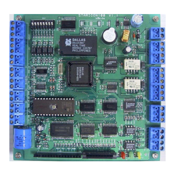
ID TECK STAR ICON100 ACCESS CONTROLLER 5. Identifying Supplied Parts Please unpack and check the contents of the box. Main Unit Manual ( 1 ) ( 1 ) 6. System Description DIP S/W Power Input TTL1,2 Reader2 Relay1,2 LED Control... -
Page 6: Connection
ID TECK STAR ICON100 ACCESS CONTROLLER 7. Connection Setting address by the addressing DIP switch 1. Initial status Initial status of the DIP switch is as follows. The address set by the DIP switch is to be used when operating with application program, so it must be set equal to application's value. - Page 7 ID TECK STAR ICON100 ACCESS CONTROLLER 2. Addressing the unit Table 1 : The relation between Setting and Dip switch 3. Initializing the unit. Toggle the switch 8 to 'off' and toggle it back to 'on' when the power is on. Then you will see a message showing the initialization is completed on the LCD.
-
Page 8: System Application
ID TECK STAR ICON100 ACCESS CONTROLLER 8. System Application D Input 2 Door Contact Relay1 EXIT Input 1 Button Relay2 +12V Reader2 Input 3 +12V +12V DC12V POWER SUPPLY Reader1 Door Lock PIR Sensor Siren 8-1. Power Connection - Connect (+) wire of DC 12V power to +12V(power port 1) port - Connect Power GND (-) wire of DC 12V to GND(power port 2) port 8-2. - Page 9 ID TECK STAR ICON100 ACCESS CONTROLLER - Connect (+) wire of Alarm Device to Alarm RELAY (NO port) wire. - Connect (-) wire of Alarm Device to Power GND (-) wire. 8-4. Exit Button Connection - Connect one of the wires of Exit Button to Exit Button Input.
-
Page 10: Wiring For Network
10. Functions 10-1. Standalone Operation The STAR ICON100 is capable of having two readers (entry and exit). The unit receives card data signals from the RF readers and determines whether or not to unlock the door. When an input signal is sent, for example from an activated sensor or if the exit button pressed, the controller generates and logs an appropriate response. - Page 11 10-7. Inputs/ Outputs The STAR ICON100 access controller has four input ports(two relay output ports and two TTL output ports) which can be used to manipulate a wide variety of controls. 10-8. Time Schedule You can program periods of time when each person(ID number) can access the door.
-
Page 12: Operation
ID TECK STAR ICON100 ACCESS CONTROLLER 11. Operation 11-1. Normal Operation Mode (Safe Mode) When the Main Unit operates in standby mode(waiting for RF card), the red LED is lit. 11-2. Open the Door When a registered card(or PIN) is read, the Door will open for 3 seconds.(default) -
Page 13: Basic Settings
ID TECK STAR ICON100 ACCESS CONTROLLER 12. Basic settings 12.1 Basic operation POWER ON H/W RESET MODE GENERAL BOOT INITIAL BEEP INITIAL BEEP LCD display : STAR ION100[F1] LCD display : STAR ION100[F1] MM/DD hh/mm/ss MM/DD hh/mm/ss LCD display model name,... - Page 14 System initialization completion 12.3 Enter into setup menu INITIAL DISPLAY (MODEL NAME, CURRENT TIME) To set or to change the STAR ICON100 access controller's operation, enter the eight-digit Master ID INPUT ? number(factory setting '00000000' ). Note You can change the Master ID. (see 13.1.7)
- Page 15 Select ‘Time setting’ in “Setup menu F1” and enter the data of year /month /date /hour /minute /second /day (15digit) as the illustration below shows. You will see the adjusted time on the LCD when finished. Master ID Select ‘Time Setting’ STAR ICON100 [F1] menu(Setup menu F1) MM/DD hh:mm:ss “00000000”...
- Page 16 12.5 Registering Cards You can register Cards(or PIN) to the system. (See, 13.3.1) Select ‘ID REGISTRATION’ in Setup menu 3, follow through illustration below shows. Master ID Select ID Registration STAR ICON100 [F1] menu (Setup menu F3) MM/DD hh:mm:ss “00000000”...
- Page 17 ID TECK STAR ICON100 ACCESS CONTROLLER When registering cards, 1. The 'PW' is for password input. The password is needed to access doors when the controller is operating in RF + PW mode. But regardless of the operating mode, it is necessary to input a password when registering.
-
Page 18: Setting Changes
12. EVENT MEMORY 13. DURESS MODE SET To set or to change the STAR ICON100’s operation, enter the eight-digit Master number (factory setting “00000000”) <ENT>key, then you are ready to set or to change all the settings of the controller. There are four main setup menus. You need to press <F1> key for setup menu F1, <F2>... - Page 19 ID TECK STAR ICON100 ACCESS CONTROLLER 13.1 Setup Menu F1 MODE SELECTION RF Only (DEFAULT) RF+P/W( PassWord ) SEARCHING KEY(key<4> or <6>) TIME SETTING 15 digit key in SEARCHING KEY(key<4> or <6>) NOT USE (DEFAULT) APB SETUP SEARCHING KEY(key<4> or <6>)
- Page 20 ID TECK STAR ICON100 ACCESS CONTROLLER SEARCHING KEY(key<4> or <6>) SYSTEM INITIALIZE SEARCHING KEY(key<4> or <6>) CARD ID CLEAR SEARCHING KEY(key<4> or <6>) TIME SCHE CLEAR SEARCHING KEY SEARCHING KEY(key<4> or <6>) RF_PIN_INPUT ENABLE DISABLE (DEFAULT) SEARCHING KEY(key<4> or <6>)
- Page 21 ID TECK STAR ICON100 ACCESS CONTROLLER This menu is to select reader1 operating mode. You may choose to use MODE SELECTION prox, PIN # verification, or both. The lower line on the LCD indicates the RF ONLY current operating mode. Press the <ENT> key to change the mode.
- Page 22 ID TECK STAR ICON100 ACCESS CONTROLLER You can select whether the Anti-Pass-Back(APB) is used or not. The APB SETUP lower line on the LCD indicates the current mode. To change mode, press NOT USE <ENT> key. Press <4> or <6> to toggle the mode, from NOT USE to USE or the APB SETUP reverse, and finish selecting by pressing <ENT>...
- Page 23 Registered use <4> and <6> keys. 13.1.8 Initializing the System This operation will initialize the STAR ICON100. Press <ENT> key, if an SYS INITIALIZE initialization is needed (first time installation or resetting in the event of a malfunction). CAUTION: Initializing will erase all stored data incl.
- Page 24 ID TECK STAR ICON100 ACCESS CONTROLLER 13.1.9 Clearing Card IDs Used to erase ALL the card ID data. stored in the device. CARD ID CLEAR If you want to do so, press <ENT> key. When this figure appears on the LCD, press <1> key to clear and <0>...
- Page 25 ID TECK STAR ICON100 ACCESS CONTROLLER 13.1.13 Setting Duress Mode DURESS MODE SET 'ENT' NOT USE(DEFAULT) SELECT KEY(4 or 6 keys) 'ESC' IF DURESS MODE USED DISPLAY CURRENT P/W DURESS P/W 'ENT' ENTER NEW P/W ( 2 digit + 'ENT') You can select whether the Duress mode is used or not.
- Page 26 ID TECK STAR ICON100 ACCESS CONTROLLER 13.2 Setup Menu F2 INDEX : 01 ~ 10 WEEKLY: HOL, SUN, MON,... SAT TIME SCHEDULE NO. : 01 ~ 05 SEARCHING KEY(key<4> or <6>) INDEX : 01 ~ 10 HOLIDAY DEFINE NO. : 01 ~ 32...
- Page 27 ID TECK STAR ICON100 ACCESS CONTROLLER 13.2.1 Registering and Changing Time Schedule TIME SCHEDULE 'ENT' DISPLAY CURRENT T/S SELECT T/S NUMBER AND INDEX (USE '2','8','4','6' KEY) 'ENT' ENTER T/S(8 DIGIT) (START TIME(hh:mm)-END TIME(hh:mm)) YES or Error NEXT? or ESC You may program time schedules to grant and restrict access for each TIME SCHEDULE user.
- Page 28 ID TECK STAR ICON100 ACCESS CONTROLLER 13.2.2 Registering and Changing Holiday Time Schedule HOLIDAY T/S 'ENT' DISPLAY CURRENT T/S SELECT T/S NUMBER AND INDEX (USE '2','8','4','6' KEY) 'ENT' ENTER T/S(4 DIGIT) (MM:DD) NEXT? or ESC YES or Error You can register up to 32 specified “holidays,” per year for each HOLIDAY T/S schedule setting.
- Page 29 ID TECK STAR ICON100 ACCESS CONTROLLER 13.2.3 Defining Outputs in Compliance with Inputs 'ENT' DISPLAY CURRENT SET IN/OUT DEFINE SELECT INDEX (USE '4','6' KEY) 'ENT' ENTER NEW TIME OR T/S INDEX (10 DIGIT OR EVEN DIGIT) + 'ENT' NEXT? or ESC...
- Page 30 ID TECK STAR ICON100 ACCESS CONTROLLER Table 2 : The relation between index(Source, Input and Output(default) ) Index No Relay1 Relay2 TTL1 TTL2 Buzzer [1] Exit button [2] Door contact [3] Input #1 [4] Input #2 [5] Tamper S/W [6] Reader(1) ID OK...
- Page 31 ID TECK STAR ICON100 ACCESS CONTROLLER 13.2.4 Setting Holiday Index You choose which Holiday time schedule ( date registration set ) is to be HOLIDAY INDEX used. The default index is “00”. Choose the schedule you programmed (01-10). If necessary, press <ENT> key.
- Page 32 ID TECK STAR ICON100 ACCESS CONTROLLER 13.3 Setup Menu F3 ID REGISTRATION CARD SEARCHING KEY(key<4> or <6>) ID DELETE ENTER ID (8 digit key in) SEARCHING KEY(key<4> or <6>) SEARCHING ID LIST DISPLAY REGISTERED ID SEARCHING KEY(key<4> or <6>) DISPLAY REGISTRATION ID...
- Page 33 ID TECK STAR ICON100 ACCESS CONTROLLER 13.3.1 Registering IDs ID REGISTRATION 'ENT' REGISTRATION SELECT CARD or KEY ? CARD PRESENT CARD ERROR DISPLAY Invalid Card ID ENTER NEW ID Invalid T/S 1 (8 digit - Card data) Invalid T/S 2...
- Page 34 ID TECK STAR ICON100 ACCESS CONTROLLER The LCD's upper line shows the number read, and the lower line XXXXXXXX indicates that the four-digit password, time schedule index and reader code PW_ _ _ _ TS_ _ RD_ are needed. Enter those values, referring to the following information. Then the registration of the card is finished, and the reader will be waiting for another card, displaying the second menu of the menu.
- Page 35 ID TECK STAR ICON100 ACCESS CONTROLLER 13.3.3 Listing Registered IDs If you wish to list the registered user IDs, press the <ENT> key in this LIST menu. This message is displayed when there is no registered users. MEMORY EMPTY An ID number, the password, the applied T/S and the reader code are XXXXXXXX displayed on the LCD, and you can scroll to the next ID using the <4>...
- Page 36 ID TECK STAR ICON100 ACCESS CONTROLLER 13.3.5 Setting Possible Registration ID Count EVENT MEMORY ID COUNT 'ENT' ENTER NO. (3 ~ 5 digit) EMPTY ? DISPLAY "EVENT MEMORY" ID COUNT VALID ? NOT EMPTY DISPLAY "INVALID COUNT" DISPLAY "ID TOTAL COUNT"...
- Page 37 ID TECK STAR ICON100 ACCESS CONTROLLER 13.4 Setup Menu F4 DISPLAY CURRENT F/W VERSION VERSION SEARCHING KEY(key<4> or <6>) SRAM TEST SRAM TEST SEARCHING KEY(key<4> or <6>) OUTPUT TEST OUTPUT TEST SEARCHING KEY(key<4> or <6>) LCD TEST LCD TEST SEARCHING KEY(key<4> or <6>)
- Page 38 ID TECK STAR ICON100 ACCESS CONTROLLER 13.4.1 VERSION The version of the controller’s firmware is displayed on the LCD. VERSION Press <4> or <6> key to look for other menus of setup menu F4. F/W : Rev. 2.5 13.4.2 SRAM TEST To test the memory, press <ENT>...
- Page 39 ID TECK STAR ICON100 ACCESS CONTROLLER To test the output performances, press <ENT> key. If the output OUTPUT TEST performance has no problems, the test will proceed as follows: First, the green LED blinks twice as the relay is being shorted and opened twice.
- Page 40 ID TECK STAR ICON100 ACCESS CONTROLLER The reader is waiting for an RF card to read. Present an RF card to the Scanning . . . reader. The test has completed successfully if the LCD displays the ID card Reader 1 number ( example shown to left ).
-
Page 41: Operating Status Indications
ID TECK STAR ICON100 ACCESS CONTROLLER This message indicates there is a problem with the communication TX data = 0 performance. Check connections and try again. Press any key to return to COMM fail the setup menu. As the test proceeds, you can see the characters being transmitted and COMM test pass ! ! received. -
Page 42: Warranty And Service
ACCESS CONTROLLER 15. Warranty and Service STAR ICON100 warranty is 2 years from the shipped date; returns must have an RMA (Return Material Authorization) number. The customer is to provide a description of the specific problem. The customer is to include serial numbers, formats, and model numbers with the items to be returned. - Page 43 ID TECK STAR ICON100 ACCESS CONTROLLER MEMO ICON100-20011128...
- Page 44 ID TECK STAR ICON100 ACCESS CONTROLLER ID TECK Co. Ltd. ICON100-20011128...
Need help?
Do you have a question about the STAR ICON100 and is the answer not in the manual?
Questions and answers