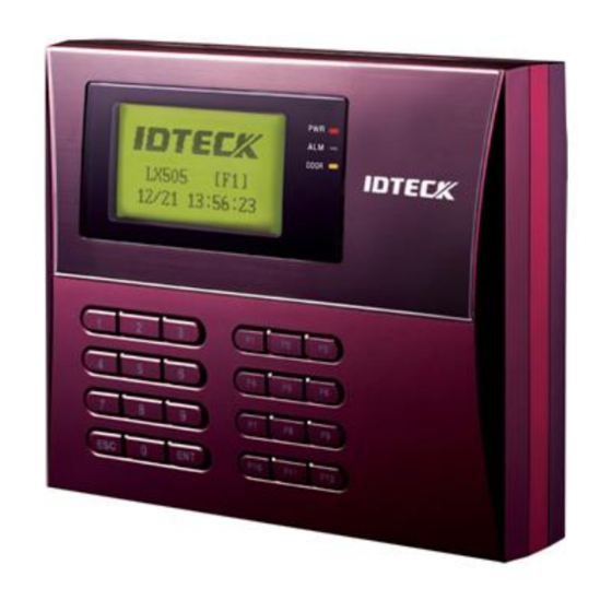
IDTECK LX505 User Manual
Proximity / pin access controller
Hide thumbs
Also See for LX505:
- User manual (72 pages) ,
- User manual (78 pages) ,
- User manual (78 pages)
Table of Contents
Advertisement
Quick Links
Advertisement
Table of Contents

Related Manuals for IDTECK LX505


Summary of Contents for IDTECK LX505
-
Page 2: Table Of Contents
Table of Contents ............Table of Contents ........... 1 Safety Information ......... 1 IMPORTANT SAFETY INSTRUCTIONS ............2 General ............3 Features ............4 Specification ..........5 Identifying Supplied Parts ........... 6 Product Overview ............. . . 1 Features ............ 11 2 Product Explanation ............ 12 2.1 Panel Description ........... . . 12... - Page 3 3 TCP/IP Communication Port Connection (Optional) .......... 27 4 Serial Printer Connection ............ 29 10 Basic Setting ........... . 29 1 Initialization of LX505 .......... 30 2 How to Enter the SETUP MENU ............ 30 3 Language Setting ............ 31 4 Date / Time Setting...
- Page 4 ............ 31 5 ID Registration ........... . 32 5.1 Registration by Card ......... . . 32 5.2 Registration Using Keypad(PIN) ............ 32 5.3 Terminology ............ 35 11 OPERATIONS ............ 35 1 Normal Operation ............ 35 2 Default Setting ........... 36 12 Setting Changes ............ 37 1 F1 SETUP MENU ............ 38...
- Page 5 ............ 52 4.1 Time Schedule ............ 52 4.2 Holiday Setting ............ 53 4.3 Holiday Code ......... . . 53 4.4 Reader#1 Mode Time Schedule ......... . . 54 4.5 Reader#2 Mode Time Schedule ........... 54 4.6 Voice Time Schedule ............ 55 5 F5 SETUP MENU .......... 56 5.1 Exit Button Output Setting .......... 57...
- Page 6 ............ 64 7.1 ID Registration ........... . . 64 Registration by Card .......... 65 Registration Using Keypad ............ 65 Terminology ............ 66 7.2 ID Delete ............. . . 67 7.3 ID List .......... 67 7.4 Master ID Registration .......... 68 Master ID Registration by Card .......... 68 Master ID Registration by PIN ........... . 68...
-
Page 7: Safety Information
Safety Information CAUTION: TO REDUCE THE RISK OF ELECTRIC SHOCK, DO NOT REMOVE COVER (OR BACK) NO USER SERVICEABLE PARTS INSIDE. REFER SERVICING TO QUALIFIE D SERVICE PERSONNEL. This symbol indicates that dangerous voltage consisting a risk of electric shock is pres ent within this unit. - Page 8 3. Do not connect multiple controllers to a single adapter. Exceeding the capacity may cau se abnormal heat generation or fire. 4. Securely plug the power cord into the power receptacle. Insecure connection may caus e fire. 5. When installing the controller, fasten it securely and firmly. The fall of controller may ca use personal injury.
-
Page 9: Important Safety Instructions
IMPORTANT SAFETY INSTRUCTIONS 1. Read these instructions. 2. Keep these instructions. 3. Heed all warnings. 4. Follow all instructions. 5. Do not use this apparatus near water. 6. Clean only with dry cloth. 7. Do not block any ventilation openings. Install in accordance with the manufacturer’s ins tructions. -
Page 10: General
The IDTECK LX505 / LX505SR has 2 relay outputs to control a door lock and an alarm relay t hat is used to warn any error. The graphic LCD supports multiple languages so that the unit can be operated anywhere in the world. -
Page 11: Features
Features 125KHz(default) proximity/13.56MHz(optional) contactless smart card reader and PIN ● Dual function for Access Control and Time & Attendance ● Register 10,000/20,000 Users & 20,000/10,000 Event Buffers (Selectable) ● Operating Mode selectable for each user ID ● 4 Level Door Open Time Setting for Individual ID ●... -
Page 12: Specification
30ms Reading Time (Card) DC 12V / Max.550mA Power / Current LX505: 1 Port for Anti-Pass Back (26bit Wiegand, 8bit Burst for PIN) LX505SR: 1 Port for Anti-Pass Back (34bit Wiegand, 8bit Burst for PIN) RS232 / RS485 (Max.32ch) Communication... - Page 13 / DC5V, Rating Max.20mA Graphic LCD (128 x 64 dots) 72.5mm x 39.5mm (2.85” x 1.56”) 24-key Keypad with Back Lighting Keypad (12 Function Keys included) English, Spanish, Portuguese (Selectable) Language LCD Display Arabic, Chinese, Korean, Japanese (Optional) English(Default), Spanish, Portuguese, Arabic, Chinese, Korean, Ja Voice Output panese (Programmable) 3 Array LED Indicators...
-
Page 14: Identifying Supplied Parts
Identifying Supplied Parts Please unpack and check the contents of the box. If any of these parts are missing, please co ntact a near-by distributor or IDTECK as soon as possible. -
Page 15: Product Overview
PC. Keypad If the IDTECK LX505 / LX505SR is not connected to the host PC, the built-in keypad a nd LCD module can be used for the entire operations and configuration process. - Page 16 Time Schedule Setup You can program up to 10 time schedules and assign one time schedule to each user. Each time schedule has 8 different time zones from Monday-Sunday (7 time zones) a nd one holiday. Each time zone has 5 different time codes so you can program 5 diffe rent time codes for each day.
-
Page 17: Product Explanation
Two Men Operation This feature is used to configure the IDTECK LX505 / LX505SR to allow a certain user (e.g. a visitor) to pass the door only when that user is accompanied by another special user (e.g. -
Page 18: Panel Description
The LCD screen displays the status of the LX505. System Operation Status LED: When the power is applied to the LX505, the red LED is turned on. When the Relay #1 operates, the green LED is turned on. When the Relay #2 operates, the yellow LED is turned on. -
Page 19: Color Coded & Wring Table
Color Coded & Wring Table I/O PORT NAME SIGNAL NAME WIRE COLOR CON-1(2PIN CONNECTOR) Main Power (+12V) DC 12V Power Ground GND (-) Black CON-2 (3PIN CONNECTOR : Serial Printer) RS232-RX Pink wire with white stripe RS232-TX Cyan wire with white stripe RS232-GND Black CON-3 (6PIN CONNECTOR) -
Page 20: Installation Tips & Check Points
Installation Tips & Check Points Check Points before Installation Selection of Cable The system installation cables should be connected as follows; p.14... -
Page 21: Recommended Cable Type And Permissible Length
Recommended Cable Type and Permissible Length Reference Description Cable Specification Maximum Distance LX505 Power (DC12V) Belden #9409, DC Power -> LX505 18 AWG 2 conductor, unshielded Reader Belden #9512, 150m (Power and Data) 22 AWG Exit Reader -> RF20 4 conductor, shielded... -
Page 22: How To Connect Termination Resistors
completely absorbed by the receiver and a portion of signal is reflected back into the transmi ssion line. The decision whether or not to use termination resistors should be based on the c able length and data rate used by the communication system. For example, if you use 9,600 baud rate and 1,200m length of cable, the propagation veloci ty of cable is 0.66 x speed of light (This value is specified by the cable manufacturer), if we a ssume the reflections will damp out in three round trip up and down the cable length, the tr... -
Page 23: Reverse Diode Connection
If you do not find either earth ground or chassis ground, then co nnect one end of shield wire to power ground. (GND of LX505) Note that if the chassis grou nd is not properly connected to the earth and floated from the ground level, then groundin g to the chassis ground will give the worst communication. -
Page 24: Installation Of Product
Installation of Product Wall Mount (Unit: mm) p.18... -
Page 25: System Initialization
(The initialization button can be found on the back of the LX505.) Then, the LCD will first display “Initialize OK? 1:Yes 0:No”. Press <1> key if you w ant to initialize the system. After all the initialization process is completed, the system will be operating in the normal mode and the LCD will display “IDTECK, LX505 [F1], Date Time”. -
Page 26: Wiring
Wiring Power Connection 1. Connect (+) wire of DC 12V Power Supply to Red wire. 2. Connect GND (-) wire of DC 12V Power Supply to Black wire. Input Connection Exit Button Connection 1. Connect one wire from an Exit Button to Orange wire. 2. -
Page 27: 2.2K Resistor Connection For Cut Off Check
2.2K Resistor Connection for Cut off Check You have to connect a 2.2K resistor between the input wire (e.g. Orange wire) and the GND to apply the Cut Off Check feature. First, select whether or not to check the cutoff status of each device from [F5 SETUP MENU] ->... -
Page 28: External Reader Connection
3. Connect Data-0 wire of the Proximity Reader to the Pink wire. 4. Connect Data-1 wire of the Proximity Reader to the Cyan wire. Compatible Readers (External Reader): LX505: Standard 26bit Wiegand Format Proximity Readers ● Standard 26bit Wiegand + 8bit Burst Format Proximity and keypad Reader ●... -
Page 29: Recommended Readers
Standard 34bit Wiegand Format Proximity Reader ● Standard 34bit Wiegand + 8bit Burst Format Proximity and keypad Reader ● Recommended Readers LX505 RF TINY, RF10/20/30/70/500, RFK101, FGR006, FGR006EX ● LX505SR SR10/20/30, SRK101, FGR006SR ● Wiring p.23... -
Page 30: Communication
2. Connect RS232-RX (Red wire with White stripe) to the pin #3 (TX) of the 9-pin connect 3. Connect GND (Black wire) to the pin #5 of the 9-pin connector. 4. Plug in the 9-pin female connector to COM Port of the host PC. 5. Install and run the LX505 Application Software. p.24... -
Page 31: Rs485 Communication Port Connection
(Max. of 32 LX505 Units can be connected) I. Connect RS485-RTX (+) (Yellow wire) of one LX505 to RS485-RTX (+) (Yellow wir e) of another LX505. II. Connect RS485-RTX (-) (Gray wire) of one LX505 to RS485-RTX (-) (Gray wire) of another LX505. RS485 Communication Port Connection... -
Page 32: Tcp/Ip Communication Port Connection (Optional)
An optional TCP/IP Module is needed for TCP/IP communication to the host PC. Follow the next instruction. 1. Connect the LAN cable of the network system to the RJ45 jack of the LX505. 2. If you install multiple LX505 units and only one TCP/IP port is available, you may connec p.26 Communication... -
Page 33: Serial Printer Connection
LX505 to TCP/IP network and then connect all the LX505 units using the RS485 multiple communication as shown in the diagram below. 3. Set a unique Communication Address for each LX505. 4. Install and run the LX505 Application Software. - Page 34 5. Set the Print Output setting to ‘Auto Print’ or ‘Manual Print’ from [F3 SETUP MENU]. p.28 Communication...
-
Page 35: Basic Setting
(The initialization button can be found on the back of the LX505.) Then, the LCD will first display “Initialize OK? 1:Yes 0:No”. Press <1> key if you w ant to initialize the system. After all the initialization process is completed, the system will be operating in the normal mode and the LCD will display “IDTECK, LX505 [F1], Date, Time”. -
Page 36: How To Enter The Setup Menu
How to Enter the SETUP MENU To set up the LX505 or to change the settings, you have to enter the SETUP MENU first. To do so, press <0> key eight (or ten) times and <ENT> key on the keypad. (The Default Master I D is ‘00000000’. -
Page 37: Date / Time Setting
Time after the time setting is completed, but the year and day will not be displayed. The LX505 has a 24-hour system. Day codes are 1 for Sunday, 2 for Monday, 3 for Tuesday, 4 for Wednesday, 5 for Thursday, 6 for Friday and 7 for Saturday. -
Page 38: Registration By Card
Registration by Card Registration Using Keypad(PIN) In case you make a typing mistake during the registration process, you can press th e F1 button to erase the errors. Terminology Scanning means the reader is waiting for an ID number to be entered. The number of the card will appear with a beep sound when you present a card. - Page 39 ‘1’ only assigns Reader#1 (Built-in Reader) and code ‘2’ assig ns Reader#2 (Exit Reader). If you enter ‘1’ in the RD field(Only Reader#1 assigned) an d try to exit through Reader#2 (Exit Reader) then the LX505 generates an error messa ge (“Access Door Error”) on the LCD display.
- Page 40 refers to the Operating Mode that the new cardholder will use on Reader#2 (Exit Rea der). ‘0’ – Depend on System Operating Mode ([F1 SETUP MENU] > [READER#2 MODE]) ‘1’ – ID Only Mode ‘2’ – ID + Password Mode You cannot apply the ID + Password Mode if Reader#2 does not have a keypad or does not use password verification.
-
Page 41: Operations
OPERATIONS Normal Operation Power on When power is applied to the LX505, the Red LED is lit. Reading of registered card When a registered card (or a PIN) is verified, the Door (Relay#1) will open for 3 secon ds (Default) with the Green LED on. -
Page 42: Setting Changes
Setting Changes To set up the LX505 or to change the settings, you have to enter the SETUP MENU first. To do so, press <0> key eight (or ten) times and <ENT> key on the keypad. (The Default Master I D is ‘00000000’. -
Page 43: F1 Setup Menu
SUBMENU by pressing <4> and <6> key. If you don’t press any key within 60 sec onds or if you press <ESC> key, the LX505 will exit the SETUP MENU and return to the norm al operating mode. You can change the Master ID in the [F7 SETUP MENU]. -
Page 44: Language
Supported languages are English, Spanish and Portuguese. ● One optional language of choice(Korean, Chinese, Japanese or Arabic) can be added. ● For addition of an optional language, please contact IDTECK. ● Date and Time Setting e.g. 200802101330152 = Feb. 10, 2008, 13:30:15, Monday Reader #1 Mode READER#1 refers to the built-in proximity reader in the unit. -
Page 45: Reader #2 Mode
The READER#2 MODE setting can be configured in the same way as READER#1 MODE setti ng in the previous section. NOTE: READER#2 refers to the Exit Reader connected to the LX505. ID ONLY Select this mode if the Exit Reader is operating without using a password ID+P/W Select this mode if the Exit Reader is using password verification. -
Page 46: Communication Address Setting
If you have a communication problem, please check the followings; ● Check the Communication Address for both the LX505 and the host PC in the Soft ○ ware.- Check the Baud Rate setting of both the LX505 and the host PC software. -
Page 47: F2 Setup Menu
F2 SETUP MENU F2 SETUP MENU p.41... -
Page 48: Event Memory
USE, the LX505 keeps all event transactions stored in the memory in case the event memory is full. On the other hand, if you select NOT USE, new events will be overwritten into the eve nt buffer. If you use the LX505 in a stand-alone configuration (just for door access), select N OT USE. -
Page 49: Time Unit Setting
Time Unit Setting This setting allows you to define the unit of time. 1sec Output Time is calculated in the time unit of 1 second for the IN/OUT definition. 0.1sec Output Time is calculated in the time unit of 1/10 second (or 100ms) for the IN/OUT definition e.g. -
Page 50: Anti-Passback Mode
This setting is related to the Output Time Schedule setting of [F5 SETUP MENU]. The Output Time Schedule setting can be used to generate outputs for a certain assigned period of time, for example to keep the door open during that time. By setting this Output T/S + ID setting t o USE, you can delay the output (e.g. -
Page 51: Duress Mode
The Duress Password and ARM and DISARM codes must differ. Wiegand Output This feature allows you to use the LX505 as a reader (as opposed to as a controller). If this se tting is set to USE, the LX505 sends 26bit Wiegand Output through two TTL output ports. (T he LX505SR sends out 34bit Wiegand output.) -
Page 52: Door Open Alarm Time Setting
NOT USE Normal TTL outputs will be activated. 26bit Wiegand outputs will be generated through TTL1 and TTL2 ports. When a regist ered card is read, the “ID SCANNING OK” message will appear on the LCD. (TTL1 : Dat a 0 TTL2 : Data 1) Door Open Alarm Time Setting The Door Open Alarm Time is the delay between the point at which the Door Relay Time fini shes and the point at which the Door Open Alarm starts ringing. -
Page 53: F3 Setup Menu
F3 SETUP MENU Print Output F3 SETUP MENU p.47... -
Page 54: Voice Volume
No printing output. Voice Volume The LX505 tells you its status out loud. You can adjust the volume of the voice from 0 (mute ) to 4 (maximum). For customized voice messages other than the default voice messages, please cont act IDTECK. -
Page 55: Arm/Disarm Setting
This setting allows you to set the Arm Code and the Disarm Code. After setting the Arm Cod e or Disarm Code, you can set the LX505 to the ARM mode by entering the ARM code and presenting an ARM/DISARM card (i.e. a card that was registered with Code 3). Once the LX 505 toggles into ARM mode, all readers freeze and stop reading cards. -
Page 56: One Time Read
One Time Read If this option is set to USE, the same card can’t be read twice in a row within 30 seconds. Max. User Setup You can select the maximum number of user registrations; 10,000 or 20,000. If the maximu m number of registrants is set to 20,000, the maximum number of event transactions beco mes 10,000. -
Page 57: F4 Setup Menu
The Name Display option is used to determine whether the unit will display the name of the user who receives access. This setting also determines whether to print name when printing events using serial printer. User names can only be downloaded from the software. If you register a new user via the device SETUP MENU, the name of the user can’t be entered and, therefore, won’t be displayed when the user receives access. -
Page 58: Time Schedule
Time Schedule There are 10 Time Schedule Codes available for users. Time Schedule Code “00” is the defaul t setting that allows access to all users at any time. The user can program the Time Schedule Codes 01 to 10. Each Time Schedule Code has 8 programmable days (i.e. Sun, Mon, Tue, W ed, Thu, Fri, Sat and Holiday) and each day has 5 Time Intervals (i.e. -
Page 59: Holiday Code
There are 10 Holiday Schedule Codes (H/S CODE) available for users. Holiday Schedule Code “00” is the default code, which includes no Holidays in it. The user can program the Holiday Schedule Codes 01 to 10. Each Holiday Schedule Code can have up to 100 programmable h olidays. -
Page 60: Reader#2 Mode Time Schedule
For example, suppose you want to access the door by only presenting a card from 09:00 to 17:00 and use the ID + PW verification for the rest of the time. Then, you can do so by settin g [R1 MODE SETTING] to ID+PW Mode, which is for the system operating mode, and then p rogram T/S Code 01 so that it can include a Time Interval between 09:00 and 17:00. -
Page 61: F5 Setup Menu
F5 SETUP MENU Table 12-1 Default Output Settings for Input Source OUTPUT Door Relay Alarm Relay TTL#1 TTL#2 Buzzer (DR) (AR) (T1) (T2) (BZ) [1] EXIT BUTTON F5 SETUP MENU p.55... -
Page 62: Exit Button Output Setting
[2] DOOR CONTACT [3] AUX Input #1 [4] AUX Input #2 [5] TAMPER ALARM [6] CUT OFF ALARM [7] DURESS ALARM [8] ARM/DISARM OU [9] DOOR TIME OUT [10] OUTPUT TIME S CHEDULE INPUT Exit Button Door Contact Sen Aux Input # Aux Input # Tamper Switc (EX) -
Page 63: Door Contact Output Setting
Alarm Relay Output TTL#1 Output TTL#2 Output Buzzer Output Door Contact Output Setting Aux Input#1 Output Setting Aux Input#2 Output Setting Tamper Alarm Output Setting Cut Off Alarm Output Setting Duress Alarm Output Setting Arm/Disarm Output Setting Door Time Output Setting The rest of output activation time settings above can be configured in the same way as the E xit Button Output Setting in the section 12.5.1, which means you can refer to that section t o get some idea as to how to do the configuration. -
Page 64: Input Time Schedule Setting
You can assign a Time Schedule Code to each output. The default Time Schedule Code for e very output is “00”, which means no Time Schedule is applied to them. Changing these settings can be very useful when you want to leave the door open during a certain time period. -
Page 65: Cut Off Check Setting
Door Contact Sensor Input T/S Code Aux Input#1 T/S Code Aux Input#2 T/S Code Tamper Switch Input T/S Code 5.12 Cut Off Check Setting You can choose whether or not to check the connection cutoff of each input port. ‘00’ mea ns not using this feature and ‘01’... -
Page 66: F6 Setup Menu
‘00’ means NO while ‘01’ means NC. The default setting is 00(NO). F6 SETUP MENU p.60 Setting Changes... -
Page 67: Output Setting For Reader#1 Id Ok Level 1
Table 12-2 Default Output Setting for Different Inputs OUTPUT Door Relay Alarm Relay TTL#1 TTL#2 Buzzer (DR) (AR) (T1) (T2) (BZ) [1] Reader#1 ID OK LV1 [2] Reader#1 ID OK LV2 [3] Reader#1 ID OK LV3 [4] Reader#1 ID OK LV4 [5] Reader#1 ID Error [6] Reader#1 T/S Error [7] Reader#1 APB Error... -
Page 68: Output Setting For Reader#1 Id Ok Level 2
Alarm Relay Output T/S Code TTL#1 Output T/S Code TTL#2 Output T/S Code Buzzer Output T/S Code Output Time setting from 12.6.2 to 12.6.14 can be configured in the same way as 12.6.1 R D1 ID OK Level 1 Output setting. Output Setting for Reader#1 ID OK Level 2 This output time is applied for the users registered with Level#2 output. -
Page 69: Output Setting For Reader#2 Id Ok Level 1
Output Setting for Reader#2 ID OK Level 1 This Output Time is applied for the users registered with Level#1 output. Output Setting for Reader#2 ID OK Level 2 This Output Time is applied for the users registered with Level#2 output. 6.10 Output Setting for Reader#2 ID OK Level 3 This Output Time is applied for the users registered with Level#3 output. -
Page 70: F7 Setup Menu
F7 SETUP MENU ID Registration Registration by Card p.64 Setting Changes... -
Page 71: Registration Using Keypad
Registration Using Keypad In case you make a typing mistake during the registration process, you can press th e F1 button to erase the errors. Terminology Scanning means the reader is waiting for an ID number to be entered. The number of the card will appear with a beep sound when you present a card. -
Page 72: Id Delete
‘1’ only assigns Reader#1 (Built-in Reader) and code ‘2’ assig ns Reader#2 (Exit Reader). If you enter ‘1’ in the RD field(Only Reader#1 assigned) an d try to exit through Reader#2 (Exit Reader) then the LX505 generates an error messa ge (“Access Door Error”) on the LCD display. -
Page 73: Id List
Registered IDs can be deleted from the LX505 by presenting the card or entering the ID num ber. After entering the ID DELETE mode, present the card you want to delete. Alternatively, you may enter an 8 digit ID number and press <ENT> key from the keypad. The ID number w ill appear on the LCD and that ID will be removed from the device and the “ID DELETED”... -
Page 74: Master Id Registration By Card
The default Master ID is “00000000” (or “0000000000” for LX505SR) without a fingerprint. Up to 10 Master IDs (from “01” to “10”) can be stored in LX505. To delete a Master ID, enter “00000000” (or “0000000000” for LX505SR) in the M aster ID Registration process. -
Page 75: Event Count
1,000 users in total can be registered (standard). You can optionally choose to regi ster up to 2,000/4,000 user IDs Event Count The LCD displays the total number of events stored in the memory. The count automatically i ncreases as a new event is recorded in the memory. The LCD in the left figure shows that a t otal of 12345 Events are stored in the memory. -
Page 76: System Initialization
System Initialization This operation is used to initialize the LX505 system. Press <ENT> key for initialization (when installing LX505 first or when resetting the system in the event of malfunction). Press the <1> key to initialize or <0> key to cancel the operation. -
Page 77: All Id Clear
All ID Clear When you want to delete all the stored User IDs, you can do so in this menu item. Press <EN T> key first, then press <1> key to clear all the registered User IDs or <0> key to cancel the op eration. -
Page 78: Default Setting
Default Setting Here, you can restore the default settings of the LX505, if necessary. Press <ENT> key and pr ess <1> key to restore the default setting values for all menus and or <0> key to cancel the o peration. -
Page 79: F9 Setup Menu
F9 SETUP MENU Firmware Version Check F9 SETUP MENU p.73... -
Page 80: Input Test
The Firmware Version of the unit is displayed on the LCD. Press <4> or <6> key to see other i tems of the menu on [F9 SETUP MENU]. Input Test The 5-digit number shows the input status, where “0” indicates that the input port is open ci rcuit, and “1”... -
Page 81: Keypad Test
“*” on the LCD. Reader Test The LCD will display “Scanning…”, which means the LX505 is waiting for a card to be presen ted. Present a card to one of the readers. When the reader successfully reads the card, the L CD displays the Reader number and the 8-digit (or 10-digit for LX505SR) card number. -
Page 82: Communication Test
If this is the case, contact IDTECK or a nearby distributor for technical supports. Communication Test You can test whether the communication works properly or not. Before executing this test, r emember to connect the RS232 TX wire (Black wire with White stripe) and the RS232 RX wi re (Red wire with White stripe) together. -
Page 83: Appendix
Appendix A. THE RELATION BETWEEN INPUT AND OUTPUT (DE FAULT) Table 13-1 Default Output Settings for Input Sources OUTPUT Door Relay Alarm Relay TTL#1 TTL#2 Buzzer (DR) (AR) (T1) (T2) (BZ) [1] EXIT BUTTON [2] DOOR CONTACT [3] AUX Input #1 [4] AUX Input #2 [5] TAMPER ALARM [6] CUT OFF ALARM... - Page 84 [12] CUT OFF CHECK [13] INPUT TYPE * Index No. [1] - [9] The values indicate the operating time of each output for the input signal.99 denotes “forever”. * Index No. [10] The values indicate the time schedule code (index) applied to each output. * Index No.
-
Page 85: Troubleshooting
2. When it is not feasible, initialize the unit as following: After the installation and connections are completed, supply power (+12V DC) to the LX505 with the initialization button being held down. Then, the LCD will first display ”Initialize OK? 1:Yes 0:No”. Press <1> key if you want t o initialize the system. - Page 86 An error in RFID card registration, time schedule setting or the system itself. Solution 1. If the LX505 used to be properly operating before, it is likely that there h as been an electric shock that damaged the internal memory and data. Ple ase initialize the unit as instructed in the manual.
- Page 87 Incorrect user setting or something wrong with internal circuits. Solution 1. If the LX505 used to operate properly before, it is likely that there has be en an electric shock that damaged the internal memory and data. Please in itialize the unit as instructed in the manual.
- Page 88 3. We recommend you use line-end resistors of 120 Ohm between the RTX (+) and RTX (-) wires when you are using the long-distance RS485 commu nication. Apply the same resistors to the Converter RS485 wires. Consult a service center or an electric technician if you are not sure how to do it. 4.
-
Page 89: Fcc Registration Information
FCC REGISTRATION INFORMATION FCC Requirements Part 15 Caution: Any changes or modifications in construction of this device which are not expressly approved by the responsible for compliance could void the user's authority to operate the e quipment. NOTE: This device complies with Part 15 of the FCC rules. Operation is subject to the following two conditions;... -
Page 90: Rma Request
RMA Request If you have any questions or problems regarding the RMA services, please contact us using t he contact information below. Friendly representatives at IDTECK are always standing by to provide the best after sales services. IDTECK Headquarter 5F, Ace Techno Tower B/D, 684-1, Deungchon-Dong,...
Need help?
Do you have a question about the LX505 and is the answer not in the manual?
Questions and answers