IDTECK Star iCON100SR User Manual
Hide thumbs
Also See for Star iCON100SR:
- Quick installation manual (25 pages) ,
- Troubleshooting manual (9 pages) ,
- Quick install manual (5 pages)
Table of Contents
Advertisement
Quick Links
Advertisement
Table of Contents

Related Manuals for IDTECK Star iCON100SR


Summary of Contents for IDTECK Star iCON100SR
-
Page 2: Table Of Contents
차례 ..............차례 ........... 1 Safety Information ......... 1 IMPORTANT SAFETY INSTRUCTIONS ............2 GENERAL ............3 FEATURES ........... . . SPECIFICATION ......... 5 IDENTIFYING SUPPLIED PARTS ..........6 PRODUCT OVERVIEW ............. 1 . Functions ............ 11 2 Board Layout ........ 15 7 INSTALLATION TIPS &... - Page 3 .......... 20 1 Dimension (Unit: inch (mm)) .......... 21 2 System Initialization of iCON100 ............ 21 3 Device Setting .......... 21 3.1 26Bit / 34Bit Wiegand Setting ........ 22 3.2 Board ID(Communication ID) Setting ............ 23 3.3 Baud Rate Setting .............. 24 4 Wiring ............. . . 24...
-
Page 4: 차례
........ 35 4 Setting Maximum Number of Cardholder IDs .......... 36 5 Registering Cardholder IDs ............ 37 11 OPERATION ............ 37 1 Normal Operation ............ 38 2 Default Setting .......... 39 12 SETTING CHANGES ............ 41 1 Setup Menu F1 ............ 42 1.1 Date and Time .......... 42... - Page 5 ............ 61 3.2 ID Deletion ............. . . 61 3.3 ID List ........... . 62 3.4 Registered ID Count ............ 63 3.5 Max User Setup ............ 64 3.6 Event List ............ 64 3.7 Event Count ............ 65 4 Setup Menu F4 ............ 66 4.1 Firmware Version ............ 66 4.2 Memory Test...
- Page 6 ......... 79 4.1 A MASTER ID may have changed.. 80 5 The device work well with RF Card, but does not work when inputting card number........ 80 5.1 Please check if Keypad is set to "ENABLE". 6 When the device have read a card, the device does not response or a different card num ............. . . 80 ber appears.
-
Page 7: Safety Information
Safety Information CAUTION: TO REDUCE THE RISK OF ELECTRIC SHOCK, DO NOT REMOVE COVER (OR BACK) NO USER SERVICEABLE PARTS INSIDE. REFER SERVICING TO QUALIFIE D SERVICE PERSONNEL. This symbol indicates that dangerous voltage consisting a risk of electric shock is pres ent within this unit. - Page 8 3. Do not connect multiple controllers to a single adapter. Exceeding the capacity may cau se abnormal heat generation or fire. 4. Securely plug the power cord into the power receptacle. Insecure connection may caus e fire. 5. When installing the controller, fasten it securely and firmly. The fall of controller may ca use personal injury.
-
Page 9: Important Safety Instructions
IMPORTANT SAFETY INSTRUCTIONS 1. Read these instructions. 2. Keep these instructions. 3. Heed all warnings. 4. Follow all instructions. 5. Do not use this apparatus near water. 6. Clean only with dry cloth. 7. Do not block any ventilation openings. Install in accordance with the manufacturer’s ins tructions. -
Page 10: General
GENERAL Star iCON100/ IDTECK iCON100SR is an intelligent 1 Door Access Controller designed to me et the market requirements for a simple and cost effective access controller. It is designed to achieve low cost as well as high security, convenience, and reliability. This user-friendly devic e is capable of storing up to 10,000 to 50,000 cardholders. -
Page 11: Features
FEATURES Intelligent Multi Doors Access Control and Time and Attendance Management ● Huge Capacity of Memory and available to control it to 10,000~50,000 Users / 50,000~ ● 10,000 Event Buffers Network Communication via RS232 / RS422 / Internal TCP/IP (Optional) ●... -
Page 12: Specification
SPECIFICATION iCON100 Model 8bit Microprocessor 128Kbyte Flash Memory Memory Program Mem 1Mbyte Flash Memory Data Memory Users and Event Buffers Defined Available(Caution: The Sum of Us User er ID and Event Buffer cannot exceed 60,000) 10,000 ~ 50,000 Users(Default: 10,000) 50,000 ~ 10,000 Event Buffers(Default: 50,000) Event Buffer DC 12V / Max.200mA... - Page 13 0 to +40C (+32 to +104F) Operating Temperature 10% to 90% Relative Humidity Non-Condensing Operating Humidity 170g (0.38lbs) / Weight / 137mm x 137mm x 18mm (5.4” x 5.4” x 0.75”) Dimension (W x H x T) Options Character LCD (2 Lines x 16 Char) / 65.6 mm x 13.8 mm (65.5”...
-
Page 14: Identifying Supplied Parts
IDENTIFYING SUPPLIED PARTS Please unpack and check the contents of the box. (Optional accessories, if purchased, may be included in the package) -
Page 15: Product Overview
. Functions Stand-Alone Operation Star iCON100/ IDTECK iCON100SR is capable of having 2 readers (1 Door Control). T he unit receives card ID numbers from the proximity readers and determines whether or not to unlock the door. When an input signal is entered, for example from a sensor activated or an exit button pressed, the controller generates and logs an appropriate r esponse by input signals. - Page 16 Keypad Registration If Star iCON100/ IDTECK iCON100SR is not connected to host PC, the integrated keyp ad and LCD display module can also be used for the entire programming process man ually.
-
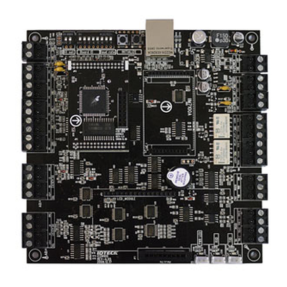
Page 17: Board Layout
tall door contact sensor to the door and you have to properly set door contact time an d outputs to alarm devices. Duress Alarm In case of duress, enter the 2 digits Duress Password and <ENT> key before the norma l access process then door will be opened as normal but the duress alarm is also gener ated at the same time and the duress alarm output will be activated to TTL output an d alarm event will be sent to the host PC. - Page 18 3 8PIN DIP Switches These switches are to set board ID and baud rate to communicate with PC. (#1~#5 DI P switches for board ID, #6~#8 DIP switches for baud rate) 4 Initialization Switches These switches are to initialize user data in the memory. To be default setting by Initia lization, press the two switches simultaneously then keep pressing more than 2 secon ds to initialize properly.
- Page 19 17 Buzzer This is an internal buzzer, which makes beep sounds when the keypad is pressed from the optional keypad. 18 LCD Display Connector This connector is to connect optional LCD display. It can be used with optional keypad for manual setup and to check the device’s set-up status. 19 Keypad Connector This connector is to connect optional keypad.
- Page 20 28 RX Status LED This is the LED to show status of reception during communication 29 TX Status LED This is the LED to show status of transmission during communication 30 MCU Module This is the optional MCU module. p.14 PRODUCT OVERVIEW...
-
Page 21: Installation Tips & Check Point
INSTALLATION TIPS & CHECK POINT Check Points before Installation Selection of Cable System installation cabling will be configured as follow. p.15... -
Page 22: Recommended Cable Type And Permissible Length Of Cable
Recommended Cable Type and Permissible Length of Cable Reference Description Cable Specification Maximum Distance ① Power (DC12V) Belden #9409, 18 AW DC Power -> iCON100 2 conductor, unshielde ②* Reader (Power and Dat Belden #9512, 22 AW 150m Extra Reader -> iCON1 4 conductor, shielded Belden #9514, 22 AW 8 conductor, shielded... -
Page 23: Check Points During Installation
Check Points during Installation Termination Resistor Termination resistors are used to match impedance of the network to the impedance of the transmission line being used. When impedance is mismatched, the transmitted signal is not completely absorbed by the receiver and a portion of signal is reflected back into the transmi ssion line. -
Page 24: Termination Resistors For 4 Wire Rs422 Communication System
Termination Resistors for 4 Wire RS422 Communication System Grounding System for Communication Cable We recommend to using proper grounding system on the communication cable. The best m ethod for grounding system is to put the shield wire of the communication cable to the 1st c lass earth grounding;... -
Page 25: Reverse Diode Connection
Reverse Diode Connection If you connect an inductor (Door Locks or Alarm device) to the output relays, there will be a high surge voltage created while the inductor is turning on and off. To protect this problem, connect the reverse diode as the figure below. It is strongly recommended to add a reverse diode between the inductor coils to a bsorb this surge voltage. -
Page 26: Installation Of The Product
INSTALLATION OF THE PRODUCT Dimension (Unit: inch (mm)) p.20... -
Page 27: System Initialization Of Icon100
System Initialization of iCON100 Initialization must be performed before first installation of iCON100. Press down the two init ialization switches simultaneously then keep pressing more than 2 seconds. Once buzzer sou nd is generated, release the switches then initialization is done and system restarts automati cally. -
Page 28: Board Id(Communication Id) Setting
If DIP switch turns from ‘ON’ to ‘OFF’ or ‘OFF’ to ‘ON’, buzzer is generated. If the buzzer does n’t stop after the DIP switch is changed, it means ID information or event is stored in the me mory. In this case, delete existing ID and event by initialization then you can change data typ e of reader port. -
Page 29: Baud Rate Setting
Baud Rate Setting Baud rate is the speed rate during communication with host PC. The 3 DIP switches are assi gned for baud rate setting on the upper left side of the iCON100 board. You can select one of 4800bps, 9600bps, 19200bps, 38400bps, 57600bps and 115200bps.You have to set ap plicable baud rate according to communication environment, and the connected devices on one loop must have the same baud rate. -
Page 30: Wiring
Wiring Power Connect (+) wire of DC 12V power to +12V terminal ● Connect GND (-) wire of DC 12V power to GND terminal ● Input Connections Exit Button Connection (Input #1) Connect one wire from an Exit Button to Input #1 ●... -
Page 31: Auxiliary Input Connection (Applied To Input #3, Input #4 And Input #5)
Auxiliary Input Connection (Applied to Input #3, Input #4 and Input #5) Connect one wire from an Auxiliary Input Device to one of the Input #3, #4 and #5. ● Connect the other wire from the Auxiliary Input Device to GND ●... -
Page 32: Door Lock (Power Fail Secure) Connection (Relay #1)
Connect COM port of Relay #1 to DC+12V ● Connect NC port of Relay #1 to (+) wire of door lock device ● Connect GND port to (-) wire of door lock devices ● Door Lock (Power Fail Secure) Connection (Relay #1) Connect COM port of Relay #1 to DC+12V ●... -
Page 33: Compatible Readers
Connect (+) wire of the Proximity Reader to DC+12V of Reader port ● Connect (-) wire of the Proximity Reader to GND of Reader port ● Connect Data-0 wire of the Proximity Reader to D0 of Reader Port ● Connect Data-1 wire of the Proximity Reader to D1 of Reader Port ●... -
Page 34: Communication
COMMUNICATION RS232 Communication Port Connection A 9-pin connector (Serial communication connector, female) is required to connect the iCO N100 to a host computer via RS232 communication. Please follow the instructions. Connect RS232-TX port of iCON100 to the pin #2(RX) of the 9-pin connector. ●... -
Page 35: Rs-422 Communication Port Connection
RS-422 Communication Port Connection RS-422 Connection (Single iCON100 Connection) An RS422/RS232 converter is required to use RS422 communication between the iCON100 and the PC. The INC400 converter is recommended for stable communication when the distan ce between the converter and the device is too far. Please follow the instructions below;... -
Page 36: Rs-422 Connection (Multiple Icon100 Connections)
RS-422 Connection (Multiple iCON100 Connections) RS422/RS232 converter is required to use RS422 communication between multiple iCON10 0s and a host computer. Please follow the following instructions. Connect RS422-TX(-) of one iCON100 to RS422-TX(-) of another iCON100. ○ Connect RS422-TX(+) of one iCON100 to RS422-TX(+) of another iCON100. ○... -
Page 37: Tcp/Ip Communication Port Connection (Optional)
TCP/IP Communication Port Connection (Optional) How to Connect TCP/IP Module to iCON100 1. As below figure, Insert TCP/IP module (IIM7100A) to iCON100 in right direction. Directi on of arrows have to be matched between iCON100 ( ) and TCP/IP ( ) modul 2. -
Page 38: Tcp/Ip Converter (External Version)
2. Set the board ID of the iCON100. 3. Install and run the iCON100 application software. TCP/IP Converter (External Version) When using the TCP/IP converter for communication, select either RS232 or RS422. INTERFACE iCON100 ILAN422 LINE COLOR TX (CON2) RX (RS232 DSUB9) BLACK+WHITE RS232 RX (CON2) -
Page 39: Initial Setup
INITIAL SETUP Initialization of iCON100 Initialization is needed before initial installation or when any function is not operated properl For initialization, press 2 initialization switches simultaneously then keep pressing more than 2 seconds. Once buzzer sound is generated, release 2 switches then initialization is done an d system restart automatically. -
Page 40: Entering Setup Mode
Entering Setup Mode To setup or to change the iCON100 settings, you have to enter the Setup Mode first. To do so, enter the Master ID (default=00000000)* and press the <ENT> key. There are 4 main Set up menus and you automatically get into “SETUP MENU F1” first. You can move to other Set up menus by pressing the <F1>... -
Page 41: Setting Maximum Number Of Cardholder Ids
Setting Maximum Number of Cardholder IDs You can set the maximum number of cardholder IDs that can be registered on your iCON10 0. By default, the iCON100 is set to store up to 10,000 cardholders and 50,000 events and y ou can adjust this setting to increase the cardholder capacity at the expense of event memor To change the ID memory setting, enter the “Setup Mode”... -
Page 42: Registering Cardholder Ids
Registering Cardholder IDs To add new cardholder IDs to the iCON100, enter the “Setup Mode”, and press <F3>. Once t he “1.REGISTRATION” item appears on the LCD, press <ENT> to begin the ID registration pro cess. For detailed information on the ID registration process, please refer to “12.3.1 REGISTRATIO N”. -
Page 43: Operation
OPERATION Normal Operation Power On When the power is supplied to iCON100, the red LED #14 is turned on. Registered Card Reading When a registered card (or PIN) is read, the door (Relay #1) will open for 3 seconds (D efaults) with the “LED #16”... -
Page 44: Default Setting
Default Setting When you operate the iCON100 first time or you initialize the iCON100, the controller will s et all values to default setting values (Factory Settings). You can change the settings for desi red application. Please refer to the “APPENDIX” section at the back of this manual for the de fault setting values. -
Page 45: Setting Changes
SETTING CHANGES p.39... - Page 46 To setup or to change the iCON100 settings, you have to enter the setup mode firs t. To do so, enter the Master ID (Default=00000000)* and press the <ENT> key. T here are 4 main Setup menus and you automatically get into “SETUP MENU F1” firs t.
-
Page 47: Setup Menu F1
Setup Menu F1 Setup Menu F1 p.41... -
Page 48: Date And Time
Date and Time The LCD displays the current time. To change the time, press <ENT>, enter 15 Digits in a “YY YYMMDDhmmssW” format, and then enter <ENT> again to confirm. NOTE: For the days of the week (W), 1 : Sun, 2 : Mon, 3 : Tue, 4 : Wed, 5 : Thu, 6 : Fri, 7 : Sat. e.g. -
Page 49: Reader1 Mode
Set the communication speed in terms of PC program. The matching values of communication speed have to be required between device and PC p rogram. Baud rates of 4800bps, 9600bps (Default), 19200bps, 38400bps, 57600bps and 115200bp s are supported, and 9600bps is recommended. When you change DIP switch, the value of ‘Baud Rate’... -
Page 50: Reader 2 Mode
RF ONLY Users can access the door by presenting their card or entering their ID number. RF + Password Users can access the door by presenting their card or entering their ID number and th en verifying their identity by a Password. Reader 2 Mode If you have an external reader connected to the iCON100 (referred to herein as Reader 2), y ou must adjust this setting according to what access mode is used on Reader 2. -
Page 51: System Initialization
/ card confidential. Beware that if you forget the Master ID, you cannot access the Setup Mode. To change the Master ID, press <ENT>, and then either enter the desired 8Digit Master ID or present a card to the reader. For the iCON100SR, the Master ID is 10Digits long in the range of 0000000000 to 4294967295. -
Page 52: All Id Clear
and exit without initialization, press <0> instead. Device address and communication speed i s maintained. All ID Clear All ID clear allows you to delete all the card ID data from the iCON100. To clear the card dat a stored in the memory, press <ENT>, and then press <1> to confirm. If you wish to cancel a nd exit, press <0>... -
Page 53: Setup Menu F2
T/S Clear allows you to delete all the data related to time scheduling, such as Time Schedule s, Holiday and Reader Time Schedules, Holiday Codes, etc. To clear the time schedule data st ored in the memory, press <ENT>, and then press <1> to confirm. If you wish to cancel and e xit, press <0>... -
Page 54: Time Schedule
Time Schedule p.48 SETTING CHANGES... - Page 55 You can define up to 10 time schedule codes. Time schedule code 00 is the default code an d can be used to allow round-the-clock access. You can define time schedule codes 01 to 10. Each time schedule code has 8 programmable days (i.e. Sun, Mon, Tue, Wed, Thu, Fri, Sat a nd holiday) and each day has 5 time intervals.
-
Page 56: Holiday Set And Change
Holiday Set and Change You can define up to 10 Holiday T/S codes. Holiday T/S code 00 is the default code without any holidays. (This means that applying Holiday T/S code 00 is the same as applying no holid ays at all.) You can define Holiday T/S codes 01 to 10. Each holiday schedule code can have up to 32 holidays defined. -
Page 57: Holiday Code
You can also define time schedule codes using the Application Software. For more information, please refer to the Software Manual. Holiday Code The Holiday code setting lets you link a holiday schedule to a time schedule. The default holi day schedule code is 00, which means no holidays are applied to the time schedule. Use <4>... -
Page 58: Input / Output Definition
Input / Output Definition In/Output Define allows you to adjust In/Output settings (Output activation time, In/Output Time Schedule, Cut-Off Check, etc.). To change the In/Output Settings, press <ENT> and select an item using <4> or <6> key, and press <ENT> again. After the cursor appears, enter the 10Digit number for the desired settin g. -
Page 59: Output Time Setting
The 14.Duress mode setting allows you to decide the output signal time for when access is granted following a duress event. When a particular event occurs, the iCON100 will generate an output signal for Re lays #1 and #2, TTL #1 and #2, and Buzzer for the length of time defined for each. Output Time Setting Output Time Set allows you to define the unit of time. -
Page 60: Anti-Passback
Anti-Passback The Anti-Pass Back feature is used to prevent an identical user from entering or exiting the d oor more than twice in a row so that employees cannot pass back their cards to their cowor kers. Anti-Pass Back can be applied only when an Exit Reader is installed. “DO NOT” enable it if an “Exit Button”... -
Page 61: Event Full Alarm
If you choose “Disable”, you cannot gain access via password input when using RF +PW mode. To enable or disable PIN Input, press <ENT> and press <4> or <6> to select “ENABLE” or “DIS ABLE”, and then press <ENT> again to confirm. Event Full Alarm Event Alarm allows you to decide whether to enable or disable the event memory full alarm. -
Page 62: Door Open Alarm Time
Duress Mode enables a cardholder under duress to activate a silent alarm to notify the securi To enable or disable the Duress Mode and / or set the Duress Password, press <ENT> and pr ess <4> or <6> to select either “DISABLE” or “ENABLE” If you select “ENABLE” the LCD will dis play the current “DURESS PASSWORD”. -
Page 63: Id Display
For this application, a Door Contact Sensor must be installed on the door. 2.12 ID Display ID DISPLAY allows you to decide whether to display the card number or the status message on the LCD when access is granted or denied. To change the setting, press <ENT> and press <4>... - Page 64 This feature only applies to the iCON100SR. By default, the iCON100SR can read smart card written in the 4BYTE format, but, for advanc ed applications, you can use 2BYTE format smart cards. To do so, you must change the Data BYTE setting to “2BYTE”.
-
Page 65: Setup Menu F3
Setup Menu F3 ID Registration Registration allows you to add new cardholders to the iCON100. To add a new cardholder I Setup Menu F3 p.59... -
Page 66: Description Of Fields
D, press <ENT>. Either present a card you wish to register to the iCON100 or enter the card number (ID) via t he keypad and press <ENT>. A Card Number (ID) can be 4 to 8Digits long. For the iCON100SR, it can be 4 to 10 Digits long. -
Page 67: Id Deletion
RD (Reader Code) To use both Reader 1 and 2 for the cardholder. Enter 0. To use just Reader1, enter 1. To use just Reader2, enter 2. The TS and RD fields do not appear if the Star iCON100 is set in Reader Mode. ID Deletion ID Delete allows you to delete existing cards from the iCON100. -
Page 68: Registered Id Count
ID List allows you to search for a certain registered card or view the list of all registered cards. To begin, press <ENT> To search for a certain registered card, press <1>. To view the entire list of all registered card s, press <2>. -
Page 69: Max User Setup
To search for a certain registered card, press <1>. To view the entire list of all registered card s, press <2>. If you have entered <1>, enter the Card Number (ID) or present the card you wish to view th e information of. -
Page 70: Event List
d vice versa. To change the memory partition setting, press <ENT>, and press <4> or <6> to s elect 10000/50000, 20000/40000, 30000/30000, 40000/20000 or 50000/10000 (No. of ID s / No. of Events), and then press <ENT> again to confirm. The event memory must be emptied prior to changing this setting. -
Page 71: Setup Menu F4
Setup Menu F4 Setup Menu F4 p.65... -
Page 72: Firmware Version
Firmware Version The version of the firmware installed in the iCON100 is displayed on the LCD. Also you can s ee the last update date. Memory Test Memory Test allows you to test the memory of the iCON100. To begin the test, press <ENT>. If the test is successful, the LCD will display the “TEST PASSED”... -
Page 73: Output Test
Output Test Output Test allows you to test the output ports of the iCON100. To begin the test, press <E NT>. First, output ports1 and 2 will be tested. During the test, relay outputs are activated and you will hear Tick-Tack sounds with the green LED blinking twice. Second, output oorts3 and 4 will be tested. -
Page 74: Lcd Test
LCD Test LCD Test allows you to test the LCD of the iCON100. To begin the test, press <ENT>. Once the test begins, the LCD will display a series of different screens. Ensure that all the scr eens on the LCD are properly displayed. The test ends with the display of the firmware upda te date (YYYY/MM/DD). -
Page 75: Reader Test
Reader Test Reader Test allows you to test the reader(s). To begin the test, press <ENT>. While the LCD displays “SCANNING”, present a card to the reader you would like to test, and the LCD will display the reader number and the card number. After the test is finished, press <ESC>... -
Page 76: Communication Test
DIP Switch 1=ON, 2=OFF (It shows how the DIP switch on the back of the ICON100 is set.) (First two for S/W3 and last eight for S/W1) Input 1-5 0=OFF (Disabled) 1=ON (Enabled) 2=Input Disconnected If you activate the Cut-Off Check feature for all the input ports in “5.IN/OUT DEFIN E”... - Page 77 If the test is successful, the LCD will display the “TEST PASSED” message. Press any key to fini sh the test. Setup Menu F4 p.71...
-
Page 78: Appendix
APPENDIX Default Values for Parameters Parameter Default Value READER #1 Operation Mode ID ONLY READER #2 Operation Mode ID ONLY READER #1 Keypad Input Limit NOT USE READER #2 Keypad Input Limit NOT USE Use of Event Memory Alarm NOT USE Unit of Time for Output Ports UNIT: 1 SEC Output Port Time Schedules... -
Page 79: Default Output Settings For Input / Output Relations
Default Output Settings for Input / Output Relations Relay#1 Relay#2 TTL#1 TTL#2 BUZZER [1] Input #1(EXIT BUTTON) [2] Input #2(Door Contact SW) [3] Input #3 [4] Input #4 [5] Input #5(TAMPER S/W) [6] Reader#1 ID OK [7] Reader#1 ID Error [8] Reader#1 ID T/S Error [9] Reader#1 APB Error [10] Reader#2 ID OK... - Page 80 * Index No. [15] The values indicate the Time Schedule Code (index) applied to each output. * Index No. [16] The values indicate the Time Schedule Code (index) applied to each input. * Index No. [19]-[21] The values indicate whether to enable or disable the feature for each output. (01-Enable, 00-Disable) p.74 APPENDIX...
-
Page 81: Troubleshooting
Troubleshooting Before requesting RMA, please check the cases below if your problem is one of them. 1 The device dose not communicate with PC. 2 When turning on the device, Date / Time is not displayed on the LCD and special char acters are displayed. -
Page 82: In The Case Of Rs422 Communication
In the case of RS422 communication See [Communication] > [RS422 Communication Port Connection] of the manual and check i f the wiring is good. p.76 Troubleshooting... -
Page 83: Please Check If The Communication Address Is Good
Please check if the communication address is good. Check communication address setting of software and the device. 1. Check if communication ID set in the device is same with communication ID set in a soft ware. See [Setting Changes] > [SETUP MENU F1] > [Communication Address (Board ID or Co mmunication ID)] and check a communication address set in the device. -
Page 84: Please Check If The Device Is Grounded Well
Resistors below 90Ω are not used as a terminal resistor. Please check if the device is grounded well. See [INSTALLATION TIPS & CHECK POINT] > [Check Points during Installation] >[Grounding System for Communication Cable] of the manual and check if the device is grounded well. If the problem persists, connect service center. -
Page 85: When Configuring The Device Using Master Id, Suddenly The Device Goes Back To The No Rmal Mode
If the problem persists, contact service center. When configuring the device using MASTER ID, sudde nly the device goes back to the normal mode. If you do not input anything for 60 seconds in setting mode, the device goes back to the normal mode. To prevent the setting from being changed by one who is not a manager, when the manage leaves the device in setting mode, the device goes back to the normal mode when there is n o input for 60 seconds. -
Page 86: The Device Work Well With Rf Card, But Does Not Work When Inputting Card Number
If the problem persists, please contact service center. The device work well with RF Card, but does not work when inputting card number. Please check if Keypad is set to "ENABLE". The default of the keypad input is "DISABLE". 1. See [Setting Changes] > [Setup Menu F2] > [RD Key Input] of the manual and set it to "USE". -
Page 87: Please Check If Wiring Between A Reader And The System
Please check if wiring between a reader and the system. See [Installation of the Product ] > [Wiring] > [Reader Wiring] of the manual and check wirin g between the reader and the device. If you use a separate power for a reader not connecting to the device, GND of the reader must be connected to GND of the device. - Page 88 II. In the case of 34 bit Cards are not authenticated if you use 26bit Wiegand format reader such as RF10/ 20/30, RFK101. If the problem persists, please contact service center p.82 Troubleshooting...
-
Page 89: Fcc Registration Information
FCC REGISTRATION INFORMATION FCC Requirements Part 15 Caution: Any changes or modifications in construction of this device which are not expressly approved by the responsible for compliance could void the user's authority to operate the e quipment. NOTE: This device complies with Part 15 of the FCC rules. Operation is subject to the following two conditions;... -
Page 90: Rma Request
RMA Request If you have any questions or problems regarding the RMA services, please contact us using t he contact information below. Friendly representatives at IDTECK are always standing by to provide the best after sales services. IDTECK Headquarter 5F, Ace Techno Tower B/D, 684-1, Deungchon-Dong,...
Need help?
Do you have a question about the Star iCON100SR and is the answer not in the manual?
Questions and answers